EP0798552B1 - Photoacoustic gas sensor - Google Patents
Photoacoustic gas sensor Download PDFInfo
- Publication number
- EP0798552B1 EP0798552B1 EP19970104373 EP97104373A EP0798552B1 EP 0798552 B1 EP0798552 B1 EP 0798552B1 EP 19970104373 EP19970104373 EP 19970104373 EP 97104373 A EP97104373 A EP 97104373A EP 0798552 B1 EP0798552 B1 EP 0798552B1
- Authority
- EP
- European Patent Office
- Prior art keywords
- microphone
- signal
- gas sensor
- monitoring
- heating element
- Prior art date
- Legal status (The legal status is an assumption and is not a legal conclusion. Google has not performed a legal analysis and makes no representation as to the accuracy of the status listed.)
- Expired - Lifetime
Links
- 239000007789 gas Substances 0.000 claims description 76
- 238000010438 heat treatment Methods 0.000 claims description 59
- 238000012544 monitoring process Methods 0.000 claims description 47
- 230000035945 sensitivity Effects 0.000 claims description 22
- 238000011156 evaluation Methods 0.000 claims description 13
- 238000012806 monitoring device Methods 0.000 claims description 8
- 230000007547 defect Effects 0.000 claims description 5
- 230000007774 longterm Effects 0.000 claims description 5
- 238000012545 processing Methods 0.000 claims description 4
- 238000001914 filtration Methods 0.000 claims description 2
- 229910001006 Constantan Inorganic materials 0.000 claims 1
- 210000004027 cell Anatomy 0.000 description 21
- 239000012528 membrane Substances 0.000 description 18
- 239000000463 material Substances 0.000 description 5
- 230000010363 phase shift Effects 0.000 description 5
- 230000003287 optical effect Effects 0.000 description 4
- 239000000853 adhesive Substances 0.000 description 2
- 230000001070 adhesive effect Effects 0.000 description 2
- 230000003321 amplification Effects 0.000 description 2
- 238000001514 detection method Methods 0.000 description 2
- 238000004519 manufacturing process Methods 0.000 description 2
- 238000003199 nucleic acid amplification method Methods 0.000 description 2
- 238000005457 optimization Methods 0.000 description 2
- 230000003595 spectral effect Effects 0.000 description 2
- 230000002123 temporal effect Effects 0.000 description 2
- SNICXCGAKADSCV-JTQLQIEISA-N (-)-Nicotine Chemical compound CN1CCC[C@H]1C1=CC=CN=C1 SNICXCGAKADSCV-JTQLQIEISA-N 0.000 description 1
- 238000010521 absorption reaction Methods 0.000 description 1
- 210000002421 cell wall Anatomy 0.000 description 1
- 230000001276 controlling effect Effects 0.000 description 1
- 230000001419 dependent effect Effects 0.000 description 1
- 230000000694 effects Effects 0.000 description 1
- 239000011888 foil Substances 0.000 description 1
- 230000007257 malfunction Effects 0.000 description 1
- 229960002715 nicotine Drugs 0.000 description 1
- SNICXCGAKADSCV-UHFFFAOYSA-N nicotine Natural products CN1CCCC1C1=CC=CN=C1 SNICXCGAKADSCV-UHFFFAOYSA-N 0.000 description 1
- 239000012811 non-conductive material Substances 0.000 description 1
- 238000004867 photoacoustic spectroscopy Methods 0.000 description 1
- 229920000515 polycarbonate Polymers 0.000 description 1
- 239000004417 polycarbonate Substances 0.000 description 1
- 230000001105 regulatory effect Effects 0.000 description 1
- 238000011160 research Methods 0.000 description 1
- 238000012552 review Methods 0.000 description 1
- 229910000679 solder Inorganic materials 0.000 description 1
Images


Classifications
-
- G—PHYSICS
- G01—MEASURING; TESTING
- G01N—INVESTIGATING OR ANALYSING MATERIALS BY DETERMINING THEIR CHEMICAL OR PHYSICAL PROPERTIES
- G01N21/00—Investigating or analysing materials by the use of optical means, i.e. using sub-millimetre waves, infrared, visible or ultraviolet light
- G01N21/17—Systems in which incident light is modified in accordance with the properties of the material investigated
- G01N21/1702—Systems in which incident light is modified in accordance with the properties of the material investigated with opto-acoustic detection, e.g. for gases or analysing solids
Definitions
- the invention relates to a photoacoustic gas sensor for measuring the concentration of gases with a measuring cell, a light source, a photodiode, a gas permeable Membrane, a microphone and a circuit for operating the light source and Evaluation of the microphone signals
- Photoacoustic gas sensors are used in research and industry to determine the Concentration of certain predominant gases used. Your areas of application include monitoring processes in bioreactors or breweries and gas concentrations in laboratories and other work rooms for compliance the maximum workplace concentrations (MAK). You represent the presence and Concentration of a gas and give when a predetermined one is exceeded An alarm or warning signal.
- MAK maximum workplace concentrations
- Photoacoustic gas sensors used today typically consist of a measuring cell with a gas permeable Membrane, a pulsed light source, a photodiode, a microphone and one electrical circuit for operating the light source and the microphone and for evaluation the microphone output signal.
- the light source sends light pulses into the measuring cell, the one Have wavelength that are absorbed by the gas to be detected.
- narrowband light sources such as light emitting diodes and lasers
- broadband Light sources such as incandescent filaments are used together with an optical bandpass filter.
- the Photodiode is used to measure the intensity of the light pulses, the resulting ones Signals of regulation of the operating voltage of the light source and compliance with one stable light intensity.
- the gas to be detected in the area of the gas sensor penetrates through the gas permeable membrane into the measuring cell and absorbs the incident light there.
- the absorption of the light pulses causes heating and expansion of the gas in the measuring cell, causing pressure modulation is generated, which is received by the microphone and converted into an electrical signal.
- the output signal of the microphone is amplified by an evaluation circuit and with Gas concentration values compared, which were saved during a calibration of the sensor are.
- the concentration of the detected gas is determined on the basis of the stored calibration values determined and, if necessary, a warning or alarm signal.
- the object of the invention is one To create photoacoustic gas sensor of the type mentioned, which is a monitoring the functional state of the microphone and the membrane as well as a calibration of the Allows microphone sensitivity.
- this object is achieved by the features of claim 1, in particular by a device for monitoring the functionality of the gas permeable membrane and the microphone and for the Carrying out a calibration of the microphone sensitivity as well as for the active, modulated Heating the air in the measuring cell to produce an artificial air the presence of gases to be detected in the measuring cell independent of pressure modulation, and by part of the circuit forming microprocessor for operation the device for generating the modulated heating and processing and Evaluation of the microphone generated due to the artificial pressure modulation Monitoring signals to determine the functional state of the microphone and the Membrane and for the detection and calibration of the microphone sensitivity, whereby by the microprocessor an assignment of the size of the monitoring signals to areas and an assessment of the temporal change in the monitoring signals is carried out and at a monitoring signal in a first positive area a message for correct Function of the gas permeable membrane and the microphone is emitted and at a Monitoring signal, which is within a second, the first adjacent area due to a long-term drift slowly changing, a calibration of the microphone sensitivity is carried
- Monitoring signals generated by the microphone are from the publication "The Photothermophones, a Device for Absolute Calibration of Photoacoustic Spectrometers "from J.C. Murphy et al in Applied Physics Letters, Vol. 31, No. 11, December 1, 1977, New York, Pages 728-730 and "Absolute Intensities in Photoacoustic Spectroscopy" by J.A. Barnes et al in Review of Scientific Instruments, Vol. 67, No. 2, February 1, 1996.
- This phoacoustic gas sensors are more for laboratory applications than for industrial ones Suitable for applications.
- the size and the temporal change in the monitoring signal being evaluated become.
- the size of the resulting monitoring signal is one of assigned to several different areas.
- the size of the monitoring signal drops in a predetermined positive range, the circuit issues a message based on it indicates that both the membrane and the microphone are working properly. Does that fall Monitoring signal in a higher compared to the first predetermined range or lower range, a microprocessor calibrates the microphone sensitivity performed by the due to the determined microphone sensitivity Gas concentration values are recalculated and saved in the EEPROM.
- predetermined threshold values are either from the monitoring signal exceeded or fallen below, the circuit issues a fault message, which indicates that either due to a leaky membrane no pressure modulation in the measuring cell has arisen, the sensitivity of the microphone has dropped to zero and / or the heating element is broken.
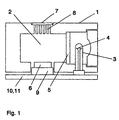
- Figure 1 shows a photoacoustic gas sensor 1 in cross section with a measuring cell 2, a lamp 3 with a filament 4 as a light source and an optical bandpass filter 5, a microphone 6 and a gas-permeable membrane 7, which lies on a perforated grid 8 and with adhesive with the measuring cell wall is tightly connected.
- a photodiode for monitoring the light intensity is not shown here.
- Broadband light pulses emanate from the filament 4 and, after spectral filtering at the bandpass filter 5, emit the measuring cell 2.
- the optical bandpass filter 5 is transparent in a narrow spectral range around the wavelength of 4.26 ⁇ m, which is absorbed by CO 2 gas.
- the gas sensor 1 has a heating element 9 which is arranged at any location in the interior of the measuring cell 2. It is preferably in the vicinity of the printed circuit board 10 with the circuit 11 for operating the gas sensor 1 and heating element 9 and for evaluating the output signals of the microphone 6.
- the heating element 9 preferably consists of a thin wire, but conventional and surface-mount Resistors and heating foils are suitable for this.
- Another embodiment of the device for heating the air is the electrical heating of the microphone housing.
- a modulated voltage is applied to the heating element 9, whereby it itself and the air in the measuring cell 2 are heated and the expansion of the air generates an artificial pressure modulation which is independent of the presence of gases to be detected.
- This pressure modulation is converted by the microphone 6 into an electrical signal, which is amplified and evaluated by the circuit 11, whereupon a message is issued which indicates whether the microphone 6 and the membrane 7 are working or the microphone sensitivity compared to the beginning of the operating time of the Gas sensor 1 has changed.
- the heating element 9 and the components of the circuit 11 and their operating parameters meet the requirements for explosion-proof operation according to the PTB.
- a heating element 9 with a corresponding resistance is therefore used and when a wire is used, its diameter, length and material are matched to this resistance.
- the material is preferably one that is chemically stable and whose resistance changes as little as possible as a function of temperature, so that the heat output emitted by the wire is stable over a long period and is independent of the temperature. Examples of suitable materials are Nikrothal and Konstantan. If a material with a higher temperature coefficient of specific resistance is used instead, the choice of the parameters of the wire would be more difficult, since the voltage applied to the heating element would have to be regulated according to the wire temperature.
- a heating element that meets the above-mentioned conditions is a wire made of nikrothal with a diameter of 30 ⁇ m and a length of 1 cm, the resistance of which is 20 ⁇ . If a current of 0.6 mA flows through this wire at an applied voltage of 12 mV, it heats up by 2.5 ° C according to the theoretical calculation, while the measured temperature increase of the wire is approx. 1 ° C.
- the parameters and the material of the wire can also be selected accordingly, so that only the requirements of temperature class T4 are met.
- Figures 2 a) and b) show a cross-section and a plan view of an example of an assembly a wire 12 as a heating element 9.
- the wire 12 is fastened on a cylindrical support 13 which attached to the microphone 6 and attached to the circuit board 10 with adhesive.
- the cylindrical carrier also serves as a holder for the microphone 6.
- the wire is guided in a notch 14, so that it is runs on the plane drawn with the dashed line and does not move from it. The purpose of this is that there is an air space under and above the wire 12 and it is electrically insulated by not coming into contact with the wall of measuring cell 2 and the microphone.
- the cylindrical carrier 13 consists of a non-conductive material, such as polycarbonate.
- the wire 12 is like a meander around several slots 15 at the top of the cylindrical Carrier 13 wound.
- the ends of the wire 12 are through holes in the center of the cylindrical Carrier 13 guided and soldered to solder joints 16 on the circuit board 10.
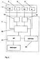
- Figure 3 shows a schematic structure of the gas sensor 1 with monitoring device.
- she shows the electrical components of the gas sensor 1, the lamp L 3, the microphone M 6, the photodiode PD 17 and the heating element HE 9 and the circuit 11 for operating the gas sensor 1 and Monitoring device.
- the circuit 11 contains a first driver circuit 18 for the Heating element 9 and a second driver circuit 19 for the lamp L 3.
- the microphone M 6th electrical signals generated on the basis of received pressure modulations become one Evaluation circuit 20 supplied, where it is linearly amplified by a high-pass and low-pass filter adjusted and rectified and smoothed synchronously by a phase sensitive rectifier become.
- the resulting DC signals are forwarded to a microprocessor MP 21, which compares them with specified comparison values.
- the microprocessor MP 21 Changes in the monitoring signal over time are included in the evaluation.
- a slow one Change such as a change over several days, is called a long-term drift evaluated, and a calibration of the microphone sensitivity is carried out by the im EEPROM 22 stored values for determining the concentration values or Gas concentration values tracked according to the change in microphone sensitivity become. This is done by determining the percentage change in the monitoring signals and the gas concentration values are changed accordingly.
- this update of the Microphone sensitivity corrects the long-term drift of the microphone.
- a message is issued by the microprocessor. such as an optical or acoustic signal that indicates a malfunction on the microphone and / or on the membrane.
- the EEPROM 22 contains further operating data of the gas sensor such as counters, temperatures of the sample gas, brightness values of the lamp 3 and phase values for the optimal amplification of the microphone signals.
- the temperatures of the sample gas are determined by an Microprocessor 20 included temperature sensors and for the recalculation of the temperature-dependent gas concentration values used by the microprocessor 21.
- the Brightness values of the lamp 3 are determined by the photodiode 17 and the evaluation circuit 20 Microprocessor 21 supplied and used for controlling the light intensity of the lamp 3, by calculating the necessary pulse duration and feeding the driver circuit 19 for the lamp 3 becomes.
- the phase values are the phase differences between the voltage signal for the heating element 9 and the output signal of the microphone 6.
- the phase values are during the manufacture of the Gas sensor 1 determines the gain of the output signal of the microphone 6 by input the phase is optimized. The phase at which the microphone signal reaches a maximum then becomes stored in EEPROM 22.
- the EEPROM 22 is a serial EEPROM with an integrated interface circuit bus (IIC bus). Thanks to this IIC bus, only one data line is required in addition to the clock line.
- the clock of the EEPROMs also serves as a clock for the heating element 9 by the clock signal of the first Driver circuit 18 for the heating element 9 is supplied.
- FIG. 4 shows an example of a time profile of a monitoring of the gas sensor 1 as a function of time t.
- Figure 4 a) shows the voltage pulses V (L) for the operation of the lamp 3. For example it is operated at 14 Hz and a duty cycle of one third.
- the voltage V (L) serves also for triggering the phase-sensitive rectifier of the evaluation circuit 20.
- a Synchronization of the lamp 3 and the heating of the heating element 9 allows an easier one Evaluation of the monitoring signals and gas signals with the same electrical components.
- the modulated voltage is preferably one for electrical crosstalk Sine function; a triangular or trapezoidal function or a function with any edges yourself too.
- Figure 4 c) shows the approximate temperature profile T (HE) of a nicotine wire from 2.5 cm in length and 30 ⁇ m in diameter, through which, according to FIG. 4 b), a current of less than 1 mA flows.
- Figure 4 d) shows a microphone signal V (M) generated by the microphone 6, in this case the monitoring signal resulting from the artificial heating of the measuring cell 2.
- the Phase shift ⁇ of the generated signal with respect to the voltage for operating the lamp 3 is the one determined during production by optimization of the microphone signal and in EEPROM 22 saved phase. Of course, microphone signals caused by the presence of detectable gases are brought about in the measuring cell, likewise with this phase shift ⁇ amplified.
- Figure 4 e shows the DC output signal Vout of the evaluation circuit 20 of the Monitoring device for a long time.
- the Monitoring device at a frequency of 1/10 Hz on and off, which it is avoided that the monitoring device is permanently in operation.
- the monitoring signal is one order of magnitude smaller than the signal from one Gas detection comes from. It can therefore be distinguished with certainty from a gas alarm signal.
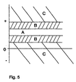
- the mean value of the signal difference D determined between the on and off state. This mean is the decisive one Magnitude of the monitoring signal and is the microprocessor 21 areas in Fig. 5th assigned.
- a preferred embodiment of the photoacoustic gas sensor has space and cost reasons small dimensions. There is an electrical problem in gas sensors of this type Crosstalk between the components while in larger photoacoustic measuring devices these problems arise less because the components are placed further apart there can.
- the heating element is located very close to the microphone in a small gas sensor. In addition, the heating element and the microphone are used to save electrical Components connected to the same supply. This often causes electrical crosstalk between the heating element and the microphone, the interference signals on the microphone signal V (M) causes.
- the operation of the photoacoustic gas sensor is similar to that shown in FIG. 4, however with an additional phase shift of the voltage for operating the heating element V (HE) and the resulting temperature profile T (HE) in Figures 4 b) and c).
- the voltage for the lamp V (L) in turn serves to trigger the phase sensitive rectifier for the Amplification of the microphone signal V (M).
- the microphone signal V (M) is used for optimization the signal strength with the phase shift ⁇ with respect to V (L) amplified.
- To the electrical The effect of the heating voltage on the microphone is reduced to a minimum Heating voltage for the heating element V (HE) in relation to the microphone signal V (M) in its phase postponed.
- the phase shift is determined experimentally so that the electrical Crosstalk falls to a minimum value. While the voltage for the heating element V (HE) in With respect to the microphone signal V (M) is out of phase, this is artificial by the heating element induced monitoring signal with the microphone signal V (M) approximately in phase.
- thermal inertia of the wire specially selected for this application Brought about heating element Brought about heating element.
- the thermal inertia is chosen experimentally so that the Temperature rise T (HE) and thus also the artificially induced monitoring signal is approximately in phase with the microphone signal V (M).
- the electrical crosstalk is the same Zero, with the monitor signal reaching 85% of its maximum value.
- the monitoring signal is interpreted in accordance with the logic table below and a message is issued. If the mean value of the signal difference D falls within the range A, the normal signal size has been reached through an intact membrane and with full microphone sensitivity, and a message is issued by the microprocessor, indicating that the membrane and the microphone are functioning correctly. If the mean falls into one of the two areas B and changes only slowly over a long period of time, a recalibration is carried out to adjust the microphone sensitivity. If, on the other hand, the change over time is fast, it is not due to a long-term drift but to a defect, and a fault message is issued.
Landscapes
- Physics & Mathematics (AREA)
- Health & Medical Sciences (AREA)
- Life Sciences & Earth Sciences (AREA)
- Chemical & Material Sciences (AREA)
- Analytical Chemistry (AREA)
- Biochemistry (AREA)
- General Health & Medical Sciences (AREA)
- General Physics & Mathematics (AREA)
- Immunology (AREA)
- Pathology (AREA)
- Investigating Or Analyzing Materials By The Use Of Ultrasonic Waves (AREA)
- Investigating Or Analysing Materials By Optical Means (AREA)
Description
Die Erfindung betrifft einen photoakustischen Gassensor für die Messung der Konzentration von Gasen mit einer Messzelle, einer Lichtquelle, einer Photodiode, einer gaspermeablen Membran, einem Mikrofon und einer Schaltung zum Betrieb der Lichtquelle und zur Auswertung der MikrofonsignaleThe invention relates to a photoacoustic gas sensor for measuring the concentration of gases with a measuring cell, a light source, a photodiode, a gas permeable Membrane, a microphone and a circuit for operating the light source and Evaluation of the microphone signals
Photoakustische Gassensoren werden in Forschung und Industrie zur Feststellung der Konzentration von bestimmten vorherrschenden Gasen eingesetzt. Ihre Anwendungsbereiche sind zum Beispiel die Überwachung von Prozessen in Bioreaktoren oder Brauereien und von Gaskonzentrationen in Laboratorien und anderen Arbeitsräumen zwecks Einhaltung der maximalen Arbeitsplatzkonzentrationen (MAK). Sie stellen die Anwesenheit und Konzentration eines Gases fest und geben bei Überschreiten einer vorgegebenen Konzentration ein Alarm- oder Warnsignal ab.Photoacoustic gas sensors are used in research and industry to determine the Concentration of certain predominant gases used. Your areas of application include monitoring processes in bioreactors or breweries and gas concentrations in laboratories and other work rooms for compliance the maximum workplace concentrations (MAK). You represent the presence and Concentration of a gas and give when a predetermined one is exceeded An alarm or warning signal.
Heute verwendete photoakustische Gassensoren, wie zum Beispiel der in der EP-A-0 151 474 beschriebene, bestehen typischerweise aus einer Messzelle mit einer gaspermeablen Membran, einer gepulst betriebenen Lichtquelle, einer Photodiode, einem Mikrofon und einer elektrischen Schaltung zum Betrieb der Lichtquelle und des Mikrofons und zur Auswertung des Mikrofonausgangssignals. Die Lichtquelle sendet Lichtpulse in die Messzelle, die eine Wellenlänge besitzen, die von dem zu detektierenden Gas absorbiert werden. Hierzu werden entweder schmalbandige Lichtquellen wie Leuchtdioden und Laser oder breitbandige Lichtquellen wie Glühwendel zusammen mit einem optischen Bandpassfilter eingesetzt. Die Photodiode dient dazu, die Intensität der Lichtpulse zu messen, wobei die von ihr resultierenden Signale der Regulierung der Betriebsspannung der Lichtquelle und Einhaltung einer stabilen Lichtintensität dienen. Befindet sich ein zu detektierendes Gas in der Umgebung des Gassensors, dringt es durch die gaspermeable Membran in die Messzelle ein und absorbiert dort das eingestrahlte Licht. Die Absorption der Lichtpulse bewirkt eine Erwärmung und Ausdehnung des Gases in der Messzelle, wodurch eine Druckmodulierung erzeugt wird, die vom Mikrofon empfangen und in ein elektrisches Signal umgewandelt wird. Das Ausgangssignal des Mikrofons wird von einer Auswerteschaltung verstärkt und mit Gaskonzentrationswerten verglichen, die bei einer Eichung des Sensors gespeichert worden sind. Aufgrund der gespeicherten Eichwerte wird die Konzentration des detektierten Gases bestimmt und gegebenenfalls ein Wam- oder Alarmsignal abgegeben.Photoacoustic gas sensors used today, such as that in EP-A-0 151 474 described, typically consist of a measuring cell with a gas permeable Membrane, a pulsed light source, a photodiode, a microphone and one electrical circuit for operating the light source and the microphone and for evaluation the microphone output signal. The light source sends light pulses into the measuring cell, the one Have wavelength that are absorbed by the gas to be detected. For this are either narrowband light sources such as light emitting diodes and lasers or broadband Light sources such as incandescent filaments are used together with an optical bandpass filter. The Photodiode is used to measure the intensity of the light pulses, the resulting ones Signals of regulation of the operating voltage of the light source and compliance with one stable light intensity. There is a gas to be detected in the area of the gas sensor, it penetrates through the gas permeable membrane into the measuring cell and absorbs the incident light there. The absorption of the light pulses causes heating and expansion of the gas in the measuring cell, causing pressure modulation is generated, which is received by the microphone and converted into an electrical signal. The output signal of the microphone is amplified by an evaluation circuit and with Gas concentration values compared, which were saved during a calibration of the sensor are. The concentration of the detected gas is determined on the basis of the stored calibration values determined and, if necessary, a warning or alarm signal.
Ist das Ausgangssignal solcher Gassensoren gleich Null, besteht die Unsicherheit, ob dieses Nullsignal einer Abwesenheit des zu detektierenden Gases entspricht oder einem Defekt an einer seiner Komponenten zugrunde liegt, wie zum Beispiel einem Abfall der Mikrofonempfindlichkeit.If the output signal of such gas sensors is zero, there is uncertainty as to whether this Zero signal corresponds to an absence of the gas to be detected or a defect underlying one of its components, such as a drop in microphone sensitivity.
Von diesem Stand der Technik ausgehend, ist der Erfindung die Aufgabe gestellt, einen photoakustischen Gassensor der eingans genannten Art zu schaffen, der eine Überwachung des Funktionszustandes des Mikrofons und der Membran sowie eine Kalibrierung der Mikrofonempfindlichkeit ermöglicht.Starting from this prior art, the object of the invention is one To create photoacoustic gas sensor of the type mentioned, which is a monitoring the functional state of the microphone and the membrane as well as a calibration of the Allows microphone sensitivity.
Diese Aufgabe wird erfindungsgemäss durch die Merkmale des Anspruchs 1 gelöst, insbesondere durch eine Vorrichtung für die Überwachung
der Funktionstüchtigkeit der gaspermeablen Membran und des Mikrofons und für die
Durchführung einer Kalibrierung der Mikrofonempfindlichkeit sowie für die aktive, modulierte
Erwärmung der in der Messzelle befindlichen Luft zwecks Erzeugung einer künstlichen, von
der Anwesenheit von zu detektierenden Gasen in der Messzelle unabhängigen Druckmodulierung,
sowie durch einen Teil der Schaltung bildenden Mikroprozessor für den Betrieb
der Vorrichtung für die Erzeugung der modulierten Erwärmung und die Verarbeitung und
Auswertung von aufgrund der künstlichen Druckmodulierung vom Mikrofon erzeugten
Überwachungssignalen zur Feststellung des Funktionszustands des Mikrofons und der
Membran und zur Feststellung und Kalibrierung der Mikrofonempfindlichkeit, wobei durch
den Mikroprozessor eine Zuordnung der Grösse der Überwachungssignale zu Bereichen
und eine Bewertung der zeitlichen Veränderung der Überwachungssignale erfolgt und bei
einem Überwachungssignal in einem ersten positiven Bereich eine Meldung für korrekte
Funktion der gaspermeablen Membran und des Mikrofons abgegeben wird und bei einem
Überwachungssignal, das sich innerhalb eines zweiten, dem ersten benachbarten Bereichs
aufgrund einer Langzeitdrift zeitlich langsam verändert, eine Kalibrierung der Mikrofonempfindlichkeit
durchgeführt wird, indem entsprechend der Grösse des Überwachungssignals
neue Gaskonzentrationswerte berechnet und in einem EEPROM abgespeichert
werden, und bei einem Überwachungssignal, das sich innerhalb dieses zweiten Bereichs
zeitlich schnell verändert oder bei einem Überwachungssignal ausserhalb des ersten und
des zweiten Bereichs eine Störungsmeldung abgegeben wird, die auf einen Defekt am
Mikrofon und/oder an der Membran hinweist.According to the invention, this object is achieved by the features of
Photoakustische Gassensoren mit einer Vorrichtung zur aktiven modulierten Erwärmung der in der Messzelle befindlichen Luft zwecks Erzeugung einer künstlichen, von der Anwesenheit von zu detektierenden Gasen in der Messzelle unabhängigen Druckmodulierung und mit einer Schaltung zum Betrieb der genannten Vorrichtung für die Erzeugung der modulierten Erwärmung und zur Verarbeitung und Auswertung von aufgrund der künstlichen Druckmodulierung vom Mikrofon erzeugten Überwachungssignalen sind aus den Publikation "The Photothermophone, a Device for Absolute Calibaration of Photoacoustic Spectrometers" von J. C. Murphy et al in Applied Physics Letters, Bd. 31, Nr. 11, 1. Dezember 1977, New York, Seiten 728-730 und "Absolute Intensities in Photoacoustic Spectroscopy" von J. A. Barnes et al in Review of Scientific Instruments, Bd. 67, Nr. 2, 1. Februar 1996, an sich bekannt. Diese phötoakustischen Gassensoren sind eher für Laboranwendungen als für industrielle Anwendungen geeignet.Photoacoustic gas sensors with a device for active modulated heating of the Air in the measuring cell for the purpose of creating an artificial presence of gases to be detected in the measuring cell independent of pressure modulation and with a circuit for operating said device for generating the modulated Heating and for processing and evaluation due to the artificial pressure modulation Monitoring signals generated by the microphone are from the publication "The Photothermophones, a Device for Absolute Calibration of Photoacoustic Spectrometers "from J.C. Murphy et al in Applied Physics Letters, Vol. 31, No. 11, December 1, 1977, New York, Pages 728-730 and "Absolute Intensities in Photoacoustic Spectroscopy" by J.A. Barnes et al in Review of Scientific Instruments, Vol. 67, No. 2, February 1, 1996. This phoacoustic gas sensors are more for laboratory applications than for industrial ones Suitable for applications.
Beim erfindungsgemässen photoakustischen Gassensor wird aufgrund des resultierenden Überwachungssignals auf die Funktionstüchtigkeit der Membran und des Mikrofons geschlossen und gegebenenfalls eine Kalibrierung der Mikrofonempfindlichkeit durchgeführt, wobei die Grösse sowie die zeitliche Veränderung des Überwachungssignals ausgewertet werden. Dabei wird die Grösse des resultierenden Überwachungssignals einem von mehreren verschiedenen Bereichen zugeordnet. Fällt die Grösse des Überwachungssignals in einen vorgegebenen positiven Bereich, gibt die Schaltung eine Meldung ab, die darauf hinweist, dass sowohl die Membran als auch das Mikrofon richtig funktionieren. Fällt das Überwachungssignals im Vergleich zum ersten vorgegebenen Bereich in einen höheren oder tieferen Bereich, wird von einem Mikroprozessor eine Kalibrierung der Mikrofonempfindlichkeit durchgeführt, indem aufgrund der festgestellten Mikrofonempfindlichkeit die Gaskonzentrationswerte neu berechnet werden und im EEPROM abgespeichert werden. Werden andererseits vorgegebene Schwellenwerte vom Überwachungssignal entweder über- oder unterschritten, gibt die Schaltung eine Störungsmeldung ab, die darauf hinweist, dass entweder durch eine undichte Membran keine Druckmodulierung in der Messzelle entstanden ist, die Empfindlichkeit des Mikrofons auf Null abgefallen und/oder das Heizelement defekt ist.In the photoacoustic gas sensor according to the invention, due to the resultant Monitoring signal for the proper functioning of the membrane and the microphone closed and if necessary a calibration of the microphone sensitivity carried out, the size and the temporal change in the monitoring signal being evaluated become. The size of the resulting monitoring signal is one of assigned to several different areas. The size of the monitoring signal drops in a predetermined positive range, the circuit issues a message based on it indicates that both the membrane and the microphone are working properly. Does that fall Monitoring signal in a higher compared to the first predetermined range or lower range, a microprocessor calibrates the microphone sensitivity performed by the due to the determined microphone sensitivity Gas concentration values are recalculated and saved in the EEPROM. On the other hand, predetermined threshold values are either from the monitoring signal exceeded or fallen below, the circuit issues a fault message, which indicates that either due to a leaky membrane no pressure modulation in the measuring cell has arisen, the sensitivity of the microphone has dropped to zero and / or the heating element is broken.
Ausführungsformen der Erfindung sind anhand der folgenden Zeichnungen erläutert.
Figur 1 zeigt einen photoakustischen Gassensor 1 im Querschnitt mit einer Messzelle 2, einer Lampe
3 mit einem Glühwendel 4 als Lichtquelle und einem optischen Bandpassfilter 5, einem Mikrofon 6
und einer gaspermeablen Membran 7, die auf einem Lochgitter 8 liegt und mit Klebstoff mit der
Messzellwand dicht verbunden ist. (Eine Photodiode zur Überwachung der Lichtintensität ist hier
nicht eingezeichnet). Vom Glühwendel 4 gehen breitbandige Lichtpulse aus, die nach einer
spektralen Filterung am Bandpassfilter 5 die Messzelle 2 ausstrahlen. Beispielsweise ist das optische
Bandpassfilter 5 in einem schmalen Spektralbereich um die Wellenlänge von 4.26 µm durchlässig,
das von CO2-Gas absorbiert wird. Befindet sich CO2-Gas in der Umgebung des Gassensors 1, dringt
es durch die gaspermeable Membran 7 in die Messzelle 2 ein, wo es das Licht absorbiert und sich
erwärmt. Durch die Erwärmung dehnt es sich aus und erzeugt eine Druckmodulierung, die vom
Mikrofon 6 in ein elektrisches Signal umgewandelt wird. Zur Überwachung der Funktion der
Membran 7 und des Mikrofons 6 weist der Gassensor 1 ein Heizelement 9 auf, das an einem
beliebigen Ort im Innenraum der Messzelle 2 angeordnet ist. Vorzugsweise ist es in der Nähe der
Leiterplatte 10 mit der Schaltung 11 zum Betrieb des Gassensors 1 und Heizelements 9 sowie zur
Auswertung der Ausgangssignale des Mikrofons 6. Das Heizelement 9 besteht vorzugsweise aus
einem dünnen Draht, wobei sich aber auch konventionelle und Surface-Mount-Widerstände sowie
Heizfolien dafür eignen. Eine weitere Ausführung der Vorrichtung der Erwärmung der Luft ist die
elektrische Erwärmung des Mikrofongehäuses. An das Heizelement 9 wird eine modulierte
Spannung angelegt, wodurch es selbst und die Luft in der Messzelle 2 erwärmt werden und durch die
Ausdehnung der Luft eine künstliche und von der Anwesenheit von zu detektierenden Gasen
unabhängige Druckmodulierung erzeugt wird. Diese Druckmodulierung wird vom Mikrofon 6 in ein
elektrisches Signal umgewandelt, das von der Schaltung 11 verstärkt und ausgewertet wird, worauf
eine Meldung abgegeben wird, die angibt, ob das Mikrofon 6 und die Membran 7 funktionieren oder
die Mikrofonempfindlichkeit im Vergleich zum Beginn der Einsatzzeit des Gassensors 1 sich
verändert hat. Das Heizelement 9 und die Komponenten der Schaltung 11 sowie ihre
Betriebsparameter erfüllen die Bestimmungen für einen explosionssicheren Betrieb gemäss des PTB.
Diese Bestimmungen, zum Beispiel die der Temperaturklassen T6 und T4 der Euronorm EN
50020:1994, setzen die Maximaltemperatur von Komponenten bei 85°C bzw. 135°C fest. Um eine
Zündfähigkeit im Falle eines Defekts des Heizelements auszuschliessen, muss auch der Strom und die
Spannung begrenzt werden. Die Strombegrenzung für das Heizelement liegt hier bei 1 mA. Die
Bestimmungen für die Temperaturklasse T6 werden von der Überwachungsvorrichtung des
Gassensors eingehalten; die Höchsttemperatur des Heizelementes 9 beträgt weniger als 85°C, und
mit dem begrenzten Stromfluss von 1 mA wird eine für die Überwachung genügende Erwärmung der
Luft erzielt. Hierbei wird die höchste Betriebstemperatur des Gassensors 1 berücksichtigt: Beträgt
diese 60°C, darf sich das Heizelement 9 um nicht mehr als 25°C erwärmen. Es wird also ein
Heizelement 9 mit entsprechendem Widerstand eingesetzt und bei Verwendung eines Drahtes sind
dessen Durchmesser, Länge und Material auf diesen Widerstand abgestimmt. Das Material ist
vorzugsweise eines, das chemisch stabil ist und dessen Widerstand sich als Funktion der Temperatur
möglichst wenig verändert, sodass die vom Draht abgegebene Wärmeleistung über lange Zeit stabil
und unabhängig von der Temperatur sind. Beispiele geeigneter Materialien sind Nikrothal und
Konstantan. Wird stattdessen ein Material mit höherem Temperaturkoeffizienten des spezifischen
Widerstands eingesetzt, wäre die Wahl der Parameter des Drahtes erschwert, da die am Heizelement
angelegte Spannung entsprechend der Drahttemperatur reguliert werden müssten. Ein Beispiel eines
Heizelementes, das den genannten Rahmenbedingungen genügt, ist ein Draht aus Nikrothal mit
einem Durchmesser von 30 µm und einer Länge von 1 cm, dessen Widerstand 20 Ω beträgt. Fliesst
ein Strom von 0.6 mA bei einer angelegten Spannung von 12 mV durch diesen Draht, erwärmt er
sich nach theoretischer Berechnung um 2.5°C, während die gemessene Temperaturerhöhung des
Drahtes ca. 1°C beträgt. Die Parameter und das Material des Drahtes können auch entsprechend
gewählt werden, sodass nur die Bestimmungen der Temperaturklasse T4 erfüllt sind.Figure 1 shows a
Figuren 2 a) und b) zeigen in einem Querschnitt bzw. einer Draufsicht ein Beispiel einer Montage
eines Drahtes 12 als Heizelement 9. Der Draht 12 ist auf einem zylindrischen Träger 13 befestigt, der
am Mikrofon 6 angefügt und mit Klebstoff an der Leiterplatte 10 befestigt ist. Um einen Luftraum
zwischen dem Mikrofon 6 und dem Draht 12 zu gewähren ist das Mikrofon 6 auf einem Absatz
befestigt. Dadurch dient der zylindrische Träger zugleich als Halterung für das Mikrofon 6. An der
Aussenseite des zylindrischen Trägers 13 ist der Draht in einer Kerbe 14 geführt, sodass sich dieser
auf der mit der gestrichelten Linie eingezeichneten Ebene verläuft und sich von ihr nicht verschiebt.
Dies bezweckt, dass unter sowie über dem Draht 12 ein Luftraum besteht und er elektrisch isoliert
ist, indem er mit der Wand der Messzelle 2 und dem Mikrofon nicht in Kontakt kommt. Der
zylindrische Träger 13 besteht aus einem nicht leitenden Material, wie zum Beispiel Polycarbonat.
Der Draht 12 ist gleich einem Mäander um mehrere Schlitze 15 am oberen Rand des zylindrischen
Trägers 13 gewunden. Die Enden des Drahtes 12 sind durch Löcher in der Mitte des zylindrischen
Trägers 13 geführt und mit Lötstellen 16 auf der Leiterplatte 10 verlötet.Figures 2 a) and b) show a cross-section and a plan view of an example of an assembly
a
Figur 3 zeigt einen schematischen Aufbau des Gassensors 1 mit Überwachungsvorrichtung. Sie zeigt
die elektrischen Komponenten des Gassensors 1, die Lampe L 3, das Mikrofon M 6, die Photodiode
PD 17 und das Heizelement HE 9 sowie die Schaltung 11 zum Betrieb des Gassensors 1 und der
Überwachungsvorrichtung. Die Schaltung 11 enthält eine erste Treiberschaltung 18 für das
Heizelement 9 und eine zweite Treiberschaltung 19 für die Lampe L 3. Die vom Mikrofon M 6
aufgrund von empfangenen Druckmodulierungen erzeugten elektrischen Signale werden einer
Auswerteschaltung 20 zugeführt, wo sie linear verstärkt, durch ein Hochpass- und Tiefpassfilter
bereinigt und durch einen phasenempfindlichen Gleichrichter synchron gleichgerichtet und geglättet
werden. Die resultierenden DC-Signale werden an einen Mikroprozessor MP 21 weitergeleitet, der
sie mit vorgegebenen Vergleichswerten vergleicht. Fallen die Grössen der Überwachungssignale in
vorgegebene Kalibrationsbereiche (siehe hierzu auch Fig. 5), bedeutet dies, dass die
Mikrofonempfindlichkeit sich verändert hat. In diesem Fall wird vom Mikroprozessor MP 21 die
zeitliche Veränderung des Überwachungssignals in der Bewertung einbezogen. Bei einer langsamen
Veränderung, wie zum Beispiel einer Veränderung über mehrere Tage, wird dies als Langzeitdrift
bewertet, und es wird eine Kalibrierung der Mikrofonempfindlichkeit durchgeführt, indem die im
EEPROM 22 gespeicherten Werte zur Bestimmung der Konzentrationswerte oder
Gaskonzentrationswerte entsprechend der Veränderung der Mikrofonempfindlichkeit nachgeführt
werden. Dies geschieht, indem die prozentuale Veränderung der Überwachungssignale bestimmt
wird und die Gaskonzentrationswerte entsprechend geändert werden. Mit dieser Nachführung der
Mikrofonempfindlichkeit wird die Langzeitdrift des Mikrofons korrigiert. Bei einer schnellen
Veränderung innerhalb der Kalibrationsbereiche sowie in dem Fall, dass die Überwachungssignale die
Kalibrationsbereiche unter- oder überschreiten, wird vom Mikroprozessor eine Meldung abgegeben,
wie zum Beispiel ein optisches oder akustisches Signal, das auf eine Störung am Mikrofon und/oder
an der Membran hinweist.Figure 3 shows a schematic structure of the
Das EEPROM 22 enthält ausser den Gaskonzentrationswerten weitere Betriebsdaten des Gassensors
wie Zähler, Temperaturen des Messgases, Helligkeitswerte der Lampe 3 und Phasenwerte für die
optimale Verstärkung der Mikrofonsignale. Die Temperaturen des Messgases werden durch einen im
Mikroprozessor 20 enthaltenen Temperaturfühler festgestellt und für die Neuberechnung der
temperaturabhängigen Gaskonzentrationswerte durch den Mikroprozessor 21 verwendet. Die
Helligkeitswerte der Lampe 3 werden von der Photodiode 17 und der Auswerteschaltung 20 dem
Mikroprozessor 21 zugeführt und für die Regelung der Lichtintensität der Lampe 3 verwendet,
indem die nötige Impulsdauer berechnet und der Treiberschaltung 19 für die Lampe 3 zugeführt
wird. Die Phasenwerte sind die Phasenunterschiede zwischen Spannungssignal für das Heizelement 9
und dem Ausgangssignal des Mikrofons 6. Die Phasenwerte werden während der Herstellung des
Gassensors 1 bestimmt, indem die Verstärkung des Ausgangssignals des Mikrofons 6 durch Eingabe
der Phase optimiert wird. Die Phase, bei der das Mikrofonsignal ein Maximum erreicht, wird sodann
im EEPROM 22 gespeichert.In addition to the gas concentration values, the
Das EEPROM 22 ist ein serielles EEPROM mit einem Integrated Interface Circuit-Bus (IIC-Bus).
Dank diesem IIC-Bus ist nebst der Clockleitung nur eine Datenleitung nötig. Die Clock des
EEPROMs dient zugleich als Clock für das Heizelement 9, indem das Clocksignal der ersten
Treiberschaltung 18 für das Heizelement 9 zugeführt wird.The
Figur 4 zeigt ein Beispiel eines zeitlichen Verlaufs einer Überwachung des Gassensors 1 als Funktion
der Zeit t. Figur 4 a) zeigt die Spannungspulse V(L) für den Betrieb der Lampe 3. Beispielsweise
wird sie bei 14 Hz und einem Arbeitszyklus von einem Drittel betrieben. Ein Heizelement zur
Erwärmung der Messzelle 2 wird, wie die modulierte Spannung V(HE) in Figur 4 b) zeigen, bei 7 Hz
betrieben, wobei die Leistungskurve die Taktfrequenz von 14 Hz hat. Die Spannung V(L) dient
zugleich auch zum Triggern des phasenempfindlichen Gleichrichters der Auswerteschaltung 20. Eine
Synchronisation der Lampe 3 und der Erwärmung des Heizelementes 9 erlaubt eine einfachere
Auswertung der Überwachungssignale und Gassignale mit denselben elektrischen Komponenten. Die
modulierte Spannung hat aus Gründen des elektrischen Übersprechens vorzugsweise eine
Sinusfunktion; eine Dreiecks- oder Trapezfunktion oder eine Funktion mit beliebigen Flanken eignen
sich ebenfalls. Figur 4 c) zeigt den ungefähren Temperaturverlauf T(HE) eines Nikrothaldrahts von
2.5 cm Länge und 30 µm im Durchmesser, durch den gemäss Figur 4 b) ein Strom von weniger als 1
mA fliesst. Figur 4 d) zeigt ein vom Mikrofon 6 erzeugtes Mikrofonsignal V(M), in diesem Fall das
von der künstlichen Erwärmung der Messzelle 2 resultierende Überwachungssignal. Die
Phasenverschiebung Δ des erzeugten Signals bezüglich der Spannung zum Betrieb der Lampe 3 ist
die bei der Herstellung durch Optimierung des Mikrofonsignals festgestellte und im EEPROM 22
gespeicherte Phase. Selbstverständlich werden Mikrofonsignale, die durch die Anwesenheit von
detektierbaren Gasen in der Messzelle herbeigeführt werden, ebenfalls mit dieser Phasenverschiebung
Δ verstärkt.FIG. 4 shows an example of a time profile of a monitoring of the
Figur 4 e) zeigt das DC-Ausgangssignal Vout der Auswerteschaltung 20 der
Überwachungsvorrichtung über längere Zeit. An diesem Betriebsbeispiel wird die
Überwachungsvorrichtung bei einer Frequenz von 1/10 Hz ein- und ausgeschaltet, wodurch
vermieden wird, dass die Überwachungsvorrichtung permanent in Betrieb ist. Das
Überwachungssignal ist jeweils um eine Grössenordnung kleiner als das Signal, das von einer
Gasdetektion herrührt. Es kann also mit Sicherheit von einem Gasalarmsignal unterschieden werden.
Über eine gegebene Zeitdauer, zum Beispiel 30 Sekunden, wird der Mittelwert der Signaldifferenz D
zwischen dem ein- und ausgeschalteten Zustand bestimmt. Dieser Mittelwert ist die massgebende
Grösse des Überwachungssignals und wird vom Mikroprozessor 21 den Bereichen in Fig. 5
zugeordnet.Figure 4 e) shows the DC output signal Vout of the
Aus Platz- und Kostengründen besitzt eine bevorzugte Ausführung des photoakustischen Gassensors kleine Dimensionen. In Gassensoren dieser Art ergibt sich ein Problem des elektrischen Übersprechens zwischen den Komponenten während in grösseren photoakustischen Messgeräten diese Probleme weniger entstehen, da die Komponenten dort weiter auseinander plaziert werden können. In einem kleinen Gassensor ist das Heizelement sehr nahe dem Mikrofon angeordnet. Zusätzlich sind das Heizelement und das Mikrofon zwecks Einsparung von elektrischen Komponenten mit derselben Speisung verbunden. Dies verursacht oft ein elektrisches Übersprechen zwischen dem Heizelement und dem Mikrofon, das Störsignale auf dem Mikrofonsignal V(M) bewirkt. Der Betrieb des photoakustischen Gassensors verläuft ähnlich wie in Figur 4 dargestellt, jedoch mit einer zusätzlichen Phasenverschiebung der Spannung zum Betrieb des Heizelements V(HE) und des resultierenden Temperaturverlaufs T(HE) in den Figuren 4 b) und c). Die Spannung für die Lampe V(L) dient wiederum zum Triggern des phasenempfindlichen Gleichrichters für die Verstärkung des Mikrofonsignals V(M). Dabei wird das Mikrofonsignal V(M) zwecks Optimierung der Signalstärke mit der Phasenverschiebung Δ bezüglich V(L) verstärkt. Um den elektrischen Einfluss der Heizspannung auf das Mikrofon auf ein Minimum zu reduzieren, wird nun die Heizspannung für das Heizelement V(HE) in Bezug auf das Mikrofonsignal V(M) in seiner Phase verschoben. Die Phasenverschiebung wird dabei experimentell so bestimmt, dass das elektrische Übersprechen auf einen Minimalwert fällt. Während die Spannung für das Heizelement V(HE) in Bezug auf das Mikrofonsignal V(M) phasenverschoben ist, ist das durch das Heizelement künstlich herbeigeführte Überwachungssignal mit dem Mikrofonsignal V(M) annähernd in Phase. Dies wird durch eine speziell für diese Anwendung gewählte thermische Trägheit des Drahtes für das Heizelement herbeigeführt. Die thermische Trägheit wird hierzu experimentell so gewählt, dass der Temperaturanstieg T(HE) und somit auch das künstlich herbeigeführte Überwachungssignal annähernd in Phase ist mit dem Mikrofonsignal V(M). Sind beispielsweise das Überwachungssignal und das Mikrofonsignal V(M) nur noch um 30° ausser Phase, ist das elektrische Übersprechen gleich Null, wobei das Überwachungssignal 85% seines Maximalwerts erreicht.A preferred embodiment of the photoacoustic gas sensor has space and cost reasons small dimensions. There is an electrical problem in gas sensors of this type Crosstalk between the components while in larger photoacoustic measuring devices these problems arise less because the components are placed further apart there can. The heating element is located very close to the microphone in a small gas sensor. In addition, the heating element and the microphone are used to save electrical Components connected to the same supply. This often causes electrical crosstalk between the heating element and the microphone, the interference signals on the microphone signal V (M) causes. The operation of the photoacoustic gas sensor is similar to that shown in FIG. 4, however with an additional phase shift of the voltage for operating the heating element V (HE) and the resulting temperature profile T (HE) in Figures 4 b) and c). The voltage for the lamp V (L) in turn serves to trigger the phase sensitive rectifier for the Amplification of the microphone signal V (M). The microphone signal V (M) is used for optimization the signal strength with the phase shift Δ with respect to V (L) amplified. To the electrical The effect of the heating voltage on the microphone is reduced to a minimum Heating voltage for the heating element V (HE) in relation to the microphone signal V (M) in its phase postponed. The phase shift is determined experimentally so that the electrical Crosstalk falls to a minimum value. While the voltage for the heating element V (HE) in With respect to the microphone signal V (M) is out of phase, this is artificial by the heating element induced monitoring signal with the microphone signal V (M) approximately in phase. this will due to a thermal inertia of the wire specially selected for this application Brought about heating element. The thermal inertia is chosen experimentally so that the Temperature rise T (HE) and thus also the artificially induced monitoring signal is approximately in phase with the microphone signal V (M). Are for example the monitoring signal and the microphone signal V (M) is only 30 ° out of phase, the electrical crosstalk is the same Zero, with the monitor signal reaching 85% of its maximum value.
Fig. 5 zeigt drei verschiedene Bereiche A, B und C. Je nach dem Bereich, in welchen der Mittelwert
fällt, wird das Überwachungssignal gemäss der nachfolgenden Logiktabelle interpretiert und eine
Meldung abgegeben. Fällt der Mittelwert der Signaldifferenz D in den Bereich A, ist durch eine
intakte Membran und bei voller Mikrofonempfindlichkeit der normale Signalgrösse erreicht worden,
und es wird vom Mikroprozessor eine Meldung abgegeben, die darauf hinweist, dass die Membran
und das Mikrofon korrekt funktionieren. Fällt der Mittelwert in einen der beiden Bereiche B und
verändert sich nur langsam über längere Zeit, wird eine Neukalibrierung zur Nachführung der
Mikrofonempfindlichkeit durchgeführt. Ist die zeitliche Veränderung dagegen schnell, liegt diese
nicht einer Langzeitdrift sondern einem Defekt zugrunde, und es erfolgt eine Störungsmeldung. Fällt
der Mittelwert in die Bereiche C, liegt die Mikrofonempfindlichkeit ausserhalb des nachführbaren
Bereichs und es wird sowohl bei einer schnellen als auch langsamen zeitlichen Veränderung eine
Störungsmeldung abgegeben.
Claims (10)
- Photo-acoustic gas sensor (1) for measuring the concentration of gases, having a measuring cell (2), a light source, a photodiode (17) a gas-permeable diaphragm (7), a microphone (6) and a circuit (11) for operating the light source and evaluating the microphone signals, characterized in a device for monitoring correct functioning of the gas-permeable diaphragm (7) and the microphone and for effecting a calibration of the microphone sensitivity and for active, modulated heating of the air situated in the measuring cell (2) for the purpose of producing an artificial pressure modulation, which is independent of the presence in the measuring cell (2) of gases to be detected, as well as in a microprocessor (21) for operating the device for producing the modulated heating, for processing and evaluating monitoring signals produced as a result of the artificial pressure modulation by the microphone (6) in order to determine the function state of the microphone (6) and the diaphragm (7) and for determining and calibrating the microphone sensitivity, the said microprocessor (21) being part of the circuit (11), wherein the values of the monitoring signals are assigned to ranges and their variation over time is evaluated by the microprocessor (21), wherein upon a monitoring signal in a first positive range a signal for correct functioning of the gas-permeable diaphragm (7) and the microphone (6) is produced, upon a monitoring signal which within a second range adjacent to the first varies slowly over time owing to a long-term drift, a calibration of the microphone sensitivity is effected by calculating in accordance with the value of the monitoring signal new gas concentration values and storing the said values in an EEPROM (22), and upon a monitoring signal, which within said second range varies rapidly over time, or upon a monitoring signal outside of the first and the second range a fault signal is produced, which indicates a defect at the microphone (6) and/or the diaphragm (7).
- Photo-acoustic gas sensor (1) according to claim 1, characterized in that the circuit (11) comprises a first driver circuit (18) for operating the light source as well as a second driver circuit (19) for operating the device for heating the air situated in the measuring cell (2), and a processing circuit (20) for amplifying and filtering the monitoring signals produced by the microphone (6), and in that in the microprocessor (21) occurs an evaluation of the monitoring signals in comparison with preset value ranges, a calculation of gas concentration values according to the determined microphone sensitivity and storing of the gas concentration values in the EEPROM (22).
- Photo-acoustic gas sensor (1) according to claim 2, characterized in that the device for modulated heating of the air situated in the measuring cell (2) comprises an electrical heating element (9), which consists of a wire (12), a resistor, a heating film or the microphone housing.
- Photo-acoustic gas sensor (1) according to claim 3, characterized in that the wire (12) is made of Nikrothal or constantan.
- Photo-acoustic gas sensor (1) according to claim 4, characterized in that the monitoring device is operated in an explosion-protected manner by a current of at most 1 mA flowing through the heating element (9) and the maximum temperature reached by the heating element (9) and the components of the circuit (11) being at most 135°C.
- Photo-acoustic gas sensor (1) according to claim 5, characterized in that the wire (12) is disposed on a cylindrical carrier (13) which is attached to the microphone.
- Photo-acoustic gas sensor (1) according to claim 6, characterized in that the cylindrical carrier (13) takes the form of a mounting for the microphone.
- Photo-acoustic gas sensor (1) according to claims 6 or 7, characterized in that the wire (12) is conveyed through slots (15) at the top edge of the cylindrical carrier (13) and in a notch (14) at the outside of the of the cylindrical carrier (13) and there is an air space both below and above the wire (12).
- Photo-acoustic gas sensor (1) according to claim 8, characterized in that the EEPROM (22) is a serial EEPROM with an IIC bus, the clock signal of which is supplied for clocking purposes to the first driver circuit (18) for operating the heating element (9).
- Photo-acoustic gas sensor (1) according to claims 3 through 9, characterized in that for minimization of the electrical cross-talk between the heating element (9) and the microphone (6) the voltage (V[HE]) for the heating element is phase shifted with respect to the microphone signal (V[M]) and the thermal inertia of the wire (12) is chosen such that the temperature (T[HE]) of the heating element and thus the electrical signal resulting from the artificial pressure modulation is approximately in phase with the microphone signal (V[M]).
Priority Applications (1)
| Application Number | Priority Date | Filing Date | Title |
|---|---|---|---|
| EP19970104373 EP0798552B1 (en) | 1996-03-25 | 1997-03-14 | Photoacoustic gas sensor |
Applications Claiming Priority (3)
| Application Number | Priority Date | Filing Date | Title |
|---|---|---|---|
| EP96104689 | 1996-03-25 | ||
| EP96104689A EP0801296A1 (en) | 1996-03-25 | 1996-03-25 | Photoacoustic gas sensor |
| EP19970104373 EP0798552B1 (en) | 1996-03-25 | 1997-03-14 | Photoacoustic gas sensor |
Publications (2)
| Publication Number | Publication Date |
|---|---|
| EP0798552A1 EP0798552A1 (en) | 1997-10-01 |
| EP0798552B1 true EP0798552B1 (en) | 2004-06-02 |
Family
ID=26141823
Family Applications (1)
| Application Number | Title | Priority Date | Filing Date |
|---|---|---|---|
| EP19970104373 Expired - Lifetime EP0798552B1 (en) | 1996-03-25 | 1997-03-14 | Photoacoustic gas sensor |
Country Status (1)
| Country | Link |
|---|---|
| EP (1) | EP0798552B1 (en) |
Cited By (1)
| Publication number | Priority date | Publication date | Assignee | Title |
|---|---|---|---|---|
| DE102006048839B4 (en) * | 2006-10-16 | 2010-01-07 | Eads Deutschland Gmbh | Photoacoustic gas sensor device with several measuring cells |
Families Citing this family (2)
| Publication number | Priority date | Publication date | Assignee | Title |
|---|---|---|---|---|
| DE59712692D1 (en) * | 1997-01-25 | 2006-08-24 | Siemens Schweiz Ag | Optoacoustic gas sensor |
| DE102017211970A1 (en) * | 2017-07-12 | 2019-01-17 | Infineon Technologies Ag | Sensor arrangement and method for testing a sensor arrangement |
Family Cites Families (3)
| Publication number | Priority date | Publication date | Assignee | Title |
|---|---|---|---|---|
| US4740086A (en) * | 1984-02-07 | 1988-04-26 | Oskar Oehler | Apparatus for the photoacoustic detection of gases |
| DK247786D0 (en) * | 1986-05-27 | 1986-05-27 | Brueel & Kjaer As | PHOTOACUSTIC GAS ANALYZER |
| JPH0621861B2 (en) * | 1987-09-28 | 1994-03-23 | 株式会社日立製作所 | Photoacoustic spectroscopy |
-
1997
- 1997-03-14 EP EP19970104373 patent/EP0798552B1/en not_active Expired - Lifetime
Cited By (1)
| Publication number | Priority date | Publication date | Assignee | Title |
|---|---|---|---|---|
| DE102006048839B4 (en) * | 2006-10-16 | 2010-01-07 | Eads Deutschland Gmbh | Photoacoustic gas sensor device with several measuring cells |
Also Published As
| Publication number | Publication date |
|---|---|
| EP0798552A1 (en) | 1997-10-01 |
Similar Documents
| Publication | Publication Date | Title |
|---|---|---|
| EP0801296A1 (en) | Photoacoustic gas sensor | |
| EP1183520B1 (en) | Gas sensor configuration | |
| DE102007039884B4 (en) | Infrared gas measuring device and method | |
| DE10113518B4 (en) | Method for measuring the degree of soiling of a protective glass of a laser processing head and laser processing system for carrying out the method | |
| DE102012007016B3 (en) | Optical gas sensor | |
| DE69628974T2 (en) | Method for controlling a Fabry-Perot interferometer with a short etalon for use in an NDIR measuring device | |
| WO1998040673A1 (en) | Method and device for analyzing combustion and for monitoring flames in a combustion chamber | |
| DE2705308B1 (en) | Device for heating a graphite tube in a graphite tube of an atomic absorption spectrometer | |
| EP3372988B1 (en) | Method and device for measuring the concentration of a substance in a gaseous medium by means of absorption spectroscopy | |
| EP3465647B1 (en) | Method and detector for determining smoke | |
| DE102019126044A1 (en) | Spectrometer device and method for calibrating a spectrometer device | |
| EP3553499A1 (en) | Gas analysis system and method for measuring nitrogen oxides in a waste gas | |
| DE102021109787A1 (en) | Method for comparing laser processing systems and method for monitoring a laser processing process and associated laser processing system | |
| EP0798552B1 (en) | Photoacoustic gas sensor | |
| DE102004028077A1 (en) | Gas sensor arrangement with shortened settling time | |
| EP1163503B1 (en) | Gas detector and method of operating a gas detector | |
| EP0421100B1 (en) | Procedure and equipment for recognizing dangerous conditions in a room | |
| DE10221708A1 (en) | Non-dispersion infrared analyzer for gas and vapor uses switch interlaced pulse- and chopper-mode measurements | |
| DE102005022288B4 (en) | Gas sensor arrangement and measuring method for improving the long-term stability | |
| DE10245822B4 (en) | Method and gas measuring cell for the detection of different gases | |
| EP4609174A1 (en) | Assembly and method for determining the concentration of one or more substances in a liquid or gaseous medium | |
| EP3206017B1 (en) | Sensor and method for determining the air ratio of a combustible gas-air mixture | |
| DE19833793C2 (en) | Method for checking the functionality of a spectrometer and spectrometer with error detection device | |
| DE19620642C2 (en) | edge sensor | |
| DE2937315A1 (en) | OPTICAL READER WITH ADAPTIVE THRESHOLD ADJUSTMENT |
Legal Events
| Date | Code | Title | Description |
|---|---|---|---|
| PUAI | Public reference made under article 153(3) epc to a published international application that has entered the european phase |
Free format text: ORIGINAL CODE: 0009012 |
|
| AK | Designated contracting states |
Kind code of ref document: A1 Designated state(s): AT BE CH DE ES FR GB IE IT LI NL PT |
|
| 17P | Request for examination filed |
Effective date: 19980318 |
|
| RAP1 | Party data changed (applicant data changed or rights of an application transferred) |
Owner name: SIEMENS BUILDING TECHNOLOGIES AG |
|
| RAP1 | Party data changed (applicant data changed or rights of an application transferred) |
Owner name: SIEMENS BUILDING TECHNOLOGIES AG |
|
| 17Q | First examination report despatched |
Effective date: 20021108 |
|
| GRAP | Despatch of communication of intention to grant a patent |
Free format text: ORIGINAL CODE: EPIDOSNIGR1 |
|
| GRAS | Grant fee paid |
Free format text: ORIGINAL CODE: EPIDOSNIGR3 |
|
| GRAA | (expected) grant |
Free format text: ORIGINAL CODE: 0009210 |
|
| AK | Designated contracting states |
Kind code of ref document: B1 Designated state(s): AT BE CH DE ES FR GB IE IT LI NL PT |
|
| REG | Reference to a national code |
Ref country code: GB Ref legal event code: FG4D Free format text: NOT ENGLISH |
|
| REG | Reference to a national code |
Ref country code: CH Ref legal event code: EP |
|
| GBT | Gb: translation of ep patent filed (gb section 77(6)(a)/1977) |
Effective date: 20040602 |
|
| REF | Corresponds to: |
Ref document number: 59711679 Country of ref document: DE Date of ref document: 20040708 Kind code of ref document: P |
|
| REG | Reference to a national code |
Ref country code: IE Ref legal event code: FG4D Free format text: GERMAN |
|
| REG | Reference to a national code |
Ref country code: PT Ref legal event code: SC4A Free format text: AVAILABILITY OF NATIONAL TRANSLATION Effective date: 20040831 |
|
| REG | Reference to a national code |
Ref country code: ES Ref legal event code: FG2A Ref document number: 2222489 Country of ref document: ES Kind code of ref document: T3 |
|
| ET | Fr: translation filed | ||
| PGFP | Annual fee paid to national office [announced via postgrant information from national office to epo] |
Ref country code: IE Payment date: 20050207 Year of fee payment: 9 |
|
| PGFP | Annual fee paid to national office [announced via postgrant information from national office to epo] |
Ref country code: PT Payment date: 20050217 Year of fee payment: 9 |
|
| PGFP | Annual fee paid to national office [announced via postgrant information from national office to epo] |
Ref country code: AT Payment date: 20050302 Year of fee payment: 9 |
|
| PGFP | Annual fee paid to national office [announced via postgrant information from national office to epo] |
Ref country code: GB Payment date: 20050303 Year of fee payment: 9 |
|
| PGFP | Annual fee paid to national office [announced via postgrant information from national office to epo] |
Ref country code: BE Payment date: 20050311 Year of fee payment: 9 |
|
| PGFP | Annual fee paid to national office [announced via postgrant information from national office to epo] |
Ref country code: NL Payment date: 20050316 Year of fee payment: 9 Ref country code: ES Payment date: 20050316 Year of fee payment: 9 |
|
| PG25 | Lapsed in a contracting state [announced via postgrant information from national office to epo] |
Ref country code: LI Free format text: LAPSE BECAUSE OF NON-PAYMENT OF DUE FEES Effective date: 20050331 Ref country code: CH Free format text: LAPSE BECAUSE OF NON-PAYMENT OF DUE FEES Effective date: 20050331 |
|
| PGFP | Annual fee paid to national office [announced via postgrant information from national office to epo] |
Ref country code: FR Payment date: 20050331 Year of fee payment: 9 |
|
| PLBE | No opposition filed within time limit |
Free format text: ORIGINAL CODE: 0009261 |
|
| STAA | Information on the status of an ep patent application or granted ep patent |
Free format text: STATUS: NO OPPOSITION FILED WITHIN TIME LIMIT |
|
| 26N | No opposition filed |
Effective date: 20050303 |
|
| PG25 | Lapsed in a contracting state [announced via postgrant information from national office to epo] |
Ref country code: DE Free format text: LAPSE BECAUSE OF NON-PAYMENT OF DUE FEES Effective date: 20051001 |
|
| REG | Reference to a national code |
Ref country code: CH Ref legal event code: PL |
|
| PG25 | Lapsed in a contracting state [announced via postgrant information from national office to epo] |
Ref country code: IE Free format text: LAPSE BECAUSE OF NON-PAYMENT OF DUE FEES Effective date: 20060314 Ref country code: GB Free format text: LAPSE BECAUSE OF NON-PAYMENT OF DUE FEES Effective date: 20060314 Ref country code: AT Free format text: LAPSE BECAUSE OF NON-PAYMENT OF DUE FEES Effective date: 20060314 |
|
| PG25 | Lapsed in a contracting state [announced via postgrant information from national office to epo] |
Ref country code: ES Free format text: LAPSE BECAUSE OF NON-PAYMENT OF DUE FEES Effective date: 20060315 |
|
| PG25 | Lapsed in a contracting state [announced via postgrant information from national office to epo] |
Ref country code: BE Free format text: LAPSE BECAUSE OF NON-PAYMENT OF DUE FEES Effective date: 20060331 |
|
| PGFP | Annual fee paid to national office [announced via postgrant information from national office to epo] |
Ref country code: IT Payment date: 20060331 Year of fee payment: 10 |
|
| PG25 | Lapsed in a contracting state [announced via postgrant information from national office to epo] |
Ref country code: PT Free format text: LAPSE BECAUSE OF NON-PAYMENT OF DUE FEES Effective date: 20060914 |
|
| PG25 | Lapsed in a contracting state [announced via postgrant information from national office to epo] |
Ref country code: NL Free format text: LAPSE BECAUSE OF NON-PAYMENT OF DUE FEES Effective date: 20061001 |
|
| GBPC | Gb: european patent ceased through non-payment of renewal fee |
Effective date: 20060314 |
|
| REG | Reference to a national code |
Ref country code: PT Ref legal event code: MM4A Free format text: LAPSE DUE TO NON-PAYMENT OF FEES Effective date: 20060914 |
|
| NLV4 | Nl: lapsed or anulled due to non-payment of the annual fee |
Effective date: 20061001 |
|
| REG | Reference to a national code |
Ref country code: IE Ref legal event code: MM4A |
|
| REG | Reference to a national code |
Ref country code: FR Ref legal event code: ST Effective date: 20061130 |
|
| REG | Reference to a national code |
Ref country code: ES Ref legal event code: FD2A Effective date: 20060315 |
|
| BERE | Be: lapsed |
Owner name: *SIEMENS BUILDING TECHNOLOGIES A.G. Effective date: 20060331 |
|
| PG25 | Lapsed in a contracting state [announced via postgrant information from national office to epo] |
Ref country code: FR Free format text: LAPSE BECAUSE OF NON-PAYMENT OF DUE FEES Effective date: 20060331 |
|
| PG25 | Lapsed in a contracting state [announced via postgrant information from national office to epo] |
Ref country code: IT Free format text: LAPSE BECAUSE OF NON-PAYMENT OF DUE FEES Effective date: 20070314 |