EP0798497B1 - Device and method for transmission control - Google Patents
Device and method for transmission control Download PDFInfo
- Publication number
- EP0798497B1 EP0798497B1 EP97105056A EP97105056A EP0798497B1 EP 0798497 B1 EP0798497 B1 EP 0798497B1 EP 97105056 A EP97105056 A EP 97105056A EP 97105056 A EP97105056 A EP 97105056A EP 0798497 B1 EP0798497 B1 EP 0798497B1
- Authority
- EP
- European Patent Office
- Prior art keywords
- clutch
- shift
- malfunctioning
- control
- transmission unit
- Prior art date
- Legal status (The legal status is an assumption and is not a legal conclusion. Google has not performed a legal analysis and makes no representation as to the accuracy of the status listed.)
- Expired - Lifetime
Links
Images

Classifications
-
- F—MECHANICAL ENGINEERING; LIGHTING; HEATING; WEAPONS; BLASTING
- F16—ENGINEERING ELEMENTS AND UNITS; GENERAL MEASURES FOR PRODUCING AND MAINTAINING EFFECTIVE FUNCTIONING OF MACHINES OR INSTALLATIONS; THERMAL INSULATION IN GENERAL
- F16D—COUPLINGS FOR TRANSMITTING ROTATION; CLUTCHES; BRAKES
- F16D48/00—External control of clutches
- F16D48/06—Control by electric or electronic means, e.g. of fluid pressure
- F16D48/068—Control by electric or electronic means, e.g. of fluid pressure using signals from a manually actuated gearshift linkage
-
- F—MECHANICAL ENGINEERING; LIGHTING; HEATING; WEAPONS; BLASTING
- F16—ENGINEERING ELEMENTS AND UNITS; GENERAL MEASURES FOR PRODUCING AND MAINTAINING EFFECTIVE FUNCTIONING OF MACHINES OR INSTALLATIONS; THERMAL INSULATION IN GENERAL
- F16H—GEARING
- F16H61/00—Control functions within control units of change-speed- or reversing-gearings for conveying rotary motion ; Control of exclusively fluid gearing, friction gearing, gearings with endless flexible members or other particular types of gearing
- F16H61/12—Detecting malfunction or potential malfunction, e.g. fail safe ; Circumventing or fixing failures
-
- B—PERFORMING OPERATIONS; TRANSPORTING
- B60—VEHICLES IN GENERAL
- B60W—CONJOINT CONTROL OF VEHICLE SUB-UNITS OF DIFFERENT TYPE OR DIFFERENT FUNCTION; CONTROL SYSTEMS SPECIALLY ADAPTED FOR HYBRID VEHICLES; ROAD VEHICLE DRIVE CONTROL SYSTEMS FOR PURPOSES NOT RELATED TO THE CONTROL OF A PARTICULAR SUB-UNIT
- B60W50/00—Details of control systems for road vehicle drive control not related to the control of a particular sub-unit, e.g. process diagnostic or vehicle driver interfaces
- B60W2050/0001—Details of the control system
- B60W2050/0043—Signal treatments, identification of variables or parameters, parameter estimation or state estimation
- B60W2050/0044—In digital systems
- B60W2050/0045—In digital systems using databus protocols
-
- B—PERFORMING OPERATIONS; TRANSPORTING
- B60—VEHICLES IN GENERAL
- B60W—CONJOINT CONTROL OF VEHICLE SUB-UNITS OF DIFFERENT TYPE OR DIFFERENT FUNCTION; CONTROL SYSTEMS SPECIALLY ADAPTED FOR HYBRID VEHICLES; ROAD VEHICLE DRIVE CONTROL SYSTEMS FOR PURPOSES NOT RELATED TO THE CONTROL OF A PARTICULAR SUB-UNIT
- B60W2510/00—Input parameters relating to a particular sub-units
- B60W2510/02—Clutches
- B60W2510/0208—Clutch engagement state, e.g. engaged or disengaged
- B60W2510/0225—Clutch actuator position
-
- F—MECHANICAL ENGINEERING; LIGHTING; HEATING; WEAPONS; BLASTING
- F16—ENGINEERING ELEMENTS AND UNITS; GENERAL MEASURES FOR PRODUCING AND MAINTAINING EFFECTIVE FUNCTIONING OF MACHINES OR INSTALLATIONS; THERMAL INSULATION IN GENERAL
- F16D—COUPLINGS FOR TRANSMITTING ROTATION; CLUTCHES; BRAKES
- F16D2500/00—External control of clutches by electric or electronic means
- F16D2500/30—Signal inputs
- F16D2500/31—Signal inputs from the vehicle
- F16D2500/3108—Vehicle speed
-
- F—MECHANICAL ENGINEERING; LIGHTING; HEATING; WEAPONS; BLASTING
- F16—ENGINEERING ELEMENTS AND UNITS; GENERAL MEASURES FOR PRODUCING AND MAINTAINING EFFECTIVE FUNCTIONING OF MACHINES OR INSTALLATIONS; THERMAL INSULATION IN GENERAL
- F16D—COUPLINGS FOR TRANSMITTING ROTATION; CLUTCHES; BRAKES
- F16D2500/00—External control of clutches by electric or electronic means
- F16D2500/30—Signal inputs
- F16D2500/31—Signal inputs from the vehicle
- F16D2500/3108—Vehicle speed
- F16D2500/3109—Vehicle acceleration
-
- F—MECHANICAL ENGINEERING; LIGHTING; HEATING; WEAPONS; BLASTING
- F16—ENGINEERING ELEMENTS AND UNITS; GENERAL MEASURES FOR PRODUCING AND MAINTAINING EFFECTIVE FUNCTIONING OF MACHINES OR INSTALLATIONS; THERMAL INSULATION IN GENERAL
- F16D—COUPLINGS FOR TRANSMITTING ROTATION; CLUTCHES; BRAKES
- F16D2500/00—External control of clutches by electric or electronic means
- F16D2500/30—Signal inputs
- F16D2500/31—Signal inputs from the vehicle
- F16D2500/3108—Vehicle speed
- F16D2500/3111—Standing still, i.e. signal detecting when the vehicle is standing still or bellow a certain limit speed
-
- F—MECHANICAL ENGINEERING; LIGHTING; HEATING; WEAPONS; BLASTING
- F16—ENGINEERING ELEMENTS AND UNITS; GENERAL MEASURES FOR PRODUCING AND MAINTAINING EFFECTIVE FUNCTIONING OF MACHINES OR INSTALLATIONS; THERMAL INSULATION IN GENERAL
- F16D—COUPLINGS FOR TRANSMITTING ROTATION; CLUTCHES; BRAKES
- F16D2500/00—External control of clutches by electric or electronic means
- F16D2500/30—Signal inputs
- F16D2500/314—Signal inputs from the user
- F16D2500/3146—Signal inputs from the user input from levers
- F16D2500/31466—Gear lever
-
- F—MECHANICAL ENGINEERING; LIGHTING; HEATING; WEAPONS; BLASTING
- F16—ENGINEERING ELEMENTS AND UNITS; GENERAL MEASURES FOR PRODUCING AND MAINTAINING EFFECTIVE FUNCTIONING OF MACHINES OR INSTALLATIONS; THERMAL INSULATION IN GENERAL
- F16D—COUPLINGS FOR TRANSMITTING ROTATION; CLUTCHES; BRAKES
- F16D2500/00—External control of clutches by electric or electronic means
- F16D2500/50—Problem to be solved by the control system
- F16D2500/51—Relating safety
- F16D2500/5114—Failsafe
-
- F—MECHANICAL ENGINEERING; LIGHTING; HEATING; WEAPONS; BLASTING
- F16—ENGINEERING ELEMENTS AND UNITS; GENERAL MEASURES FOR PRODUCING AND MAINTAINING EFFECTIVE FUNCTIONING OF MACHINES OR INSTALLATIONS; THERMAL INSULATION IN GENERAL
- F16D—COUPLINGS FOR TRANSMITTING ROTATION; CLUTCHES; BRAKES
- F16D2500/00—External control of clutches by electric or electronic means
- F16D2500/70—Details about the implementation of the control system
- F16D2500/704—Output parameters from the control unit; Target parameters to be controlled
- F16D2500/70402—Actuator parameters
- F16D2500/7041—Position
-
- F—MECHANICAL ENGINEERING; LIGHTING; HEATING; WEAPONS; BLASTING
- F16—ENGINEERING ELEMENTS AND UNITS; GENERAL MEASURES FOR PRODUCING AND MAINTAINING EFFECTIVE FUNCTIONING OF MACHINES OR INSTALLATIONS; THERMAL INSULATION IN GENERAL
- F16D—COUPLINGS FOR TRANSMITTING ROTATION; CLUTCHES; BRAKES
- F16D2500/00—External control of clutches by electric or electronic means
- F16D2500/70—Details about the implementation of the control system
- F16D2500/704—Output parameters from the control unit; Target parameters to be controlled
- F16D2500/70464—Transmission parameters
- F16D2500/70488—Selection of the gear ratio
-
- F—MECHANICAL ENGINEERING; LIGHTING; HEATING; WEAPONS; BLASTING
- F16—ENGINEERING ELEMENTS AND UNITS; GENERAL MEASURES FOR PRODUCING AND MAINTAINING EFFECTIVE FUNCTIONING OF MACHINES OR INSTALLATIONS; THERMAL INSULATION IN GENERAL
- F16H—GEARING
- F16H61/00—Control functions within control units of change-speed- or reversing-gearings for conveying rotary motion ; Control of exclusively fluid gearing, friction gearing, gearings with endless flexible members or other particular types of gearing
- F16H61/12—Detecting malfunction or potential malfunction, e.g. fail safe ; Circumventing or fixing failures
- F16H2061/122—Avoiding failures by using redundant parts
-
- F—MECHANICAL ENGINEERING; LIGHTING; HEATING; WEAPONS; BLASTING
- F16—ENGINEERING ELEMENTS AND UNITS; GENERAL MEASURES FOR PRODUCING AND MAINTAINING EFFECTIVE FUNCTIONING OF MACHINES OR INSTALLATIONS; THERMAL INSULATION IN GENERAL
- F16H—GEARING
- F16H61/00—Control functions within control units of change-speed- or reversing-gearings for conveying rotary motion ; Control of exclusively fluid gearing, friction gearing, gearings with endless flexible members or other particular types of gearing
- F16H61/12—Detecting malfunction or potential malfunction, e.g. fail safe ; Circumventing or fixing failures
- F16H2061/1232—Bringing the control into a predefined state, e.g. giving priority to particular actuators or gear ratios
-
- F—MECHANICAL ENGINEERING; LIGHTING; HEATING; WEAPONS; BLASTING
- F16—ENGINEERING ELEMENTS AND UNITS; GENERAL MEASURES FOR PRODUCING AND MAINTAINING EFFECTIVE FUNCTIONING OF MACHINES OR INSTALLATIONS; THERMAL INSULATION IN GENERAL
- F16H—GEARING
- F16H61/00—Control functions within control units of change-speed- or reversing-gearings for conveying rotary motion ; Control of exclusively fluid gearing, friction gearing, gearings with endless flexible members or other particular types of gearing
- F16H61/12—Detecting malfunction or potential malfunction, e.g. fail safe ; Circumventing or fixing failures
- F16H2061/1244—Keeping the current state
-
- F—MECHANICAL ENGINEERING; LIGHTING; HEATING; WEAPONS; BLASTING
- F16—ENGINEERING ELEMENTS AND UNITS; GENERAL MEASURES FOR PRODUCING AND MAINTAINING EFFECTIVE FUNCTIONING OF MACHINES OR INSTALLATIONS; THERMAL INSULATION IN GENERAL
- F16H—GEARING
- F16H61/00—Control functions within control units of change-speed- or reversing-gearings for conveying rotary motion ; Control of exclusively fluid gearing, friction gearing, gearings with endless flexible members or other particular types of gearing
- F16H61/12—Detecting malfunction or potential malfunction, e.g. fail safe ; Circumventing or fixing failures
- F16H2061/1256—Detecting malfunction or potential malfunction, e.g. fail safe ; Circumventing or fixing failures characterised by the parts or units where malfunctioning was assumed or detected
- F16H2061/126—Detecting malfunction or potential malfunction, e.g. fail safe ; Circumventing or fixing failures characterised by the parts or units where malfunctioning was assumed or detected the failing part is the controller
- F16H2061/1268—Electric parts of the controller, e.g. a defect solenoid, wiring or microprocessor
-
- F—MECHANICAL ENGINEERING; LIGHTING; HEATING; WEAPONS; BLASTING
- F16—ENGINEERING ELEMENTS AND UNITS; GENERAL MEASURES FOR PRODUCING AND MAINTAINING EFFECTIVE FUNCTIONING OF MACHINES OR INSTALLATIONS; THERMAL INSULATION IN GENERAL
- F16H—GEARING
- F16H59/00—Control inputs to control units of change-speed- or reversing-gearings for conveying rotary motion
- F16H59/36—Inputs being a function of speed
- F16H59/44—Inputs being a function of speed dependent on machine speed, e.g. the vehicle speed
Definitions
- the present invention relates to a device and a method for transmission control.
- Control devices for vehicle transmission units are known, in which an electronic circuit supplies control signals for a first and a second actuator unit which are able to operate, respectively, the actuation of a clutch and the selection and engagement/disengagement of the gears of a shift associated with this clutch.
- the known electronic circuits comprise at least one microprocessor which generates the clutch and shift actuation signals on the basis of a plurality of input signals, for example representative of a manually selected gear, of the working conditions of the engine, etc.
- control signals may be completely lacking or may be generated in an entirely chance manner making the transmission unit unusable and giving rise, as a consequence, to the unmanageability of the vehicle.
- any failing in traction due to the accidental opening of the clutch or to the accidental disengaging of the engaged gear may give rise to the loss of control of the vehicle. Similar considerations may hold in the event of a malfunctioning of the microprocessor while the vehicle is travelling along a steeply descending stretch of road.
- the object of the present invention is to produce a transmission control device which overcomes the drawbacks of the known devices.
- Document GB-A-2 191 875 describes an electronic control device for a transmission unit as described in the preamble of claim 1.
- the above object is achieved by the present invention as the latter relates to a transmission control device of the type described in Claim 1.
- the present invention furthermore relates to a method of transmission control of the type described in Claim 13.
- a transmission control device is indicated 1, as a whole, cooperating with an internal combustion engine 3, for example a petrol engine or a diesel engine.
- the engine 3 cooperates with an electronic engine-control facility 5 which receives as input a plurality of information parameters P measured mainly in the engine 3 and supplies control signals for the ignition system (not illustrated) and an injection system (not illustrated) of the engine 3.
- the engine 3 has an output shaft 8 able to provide mechanical power to the input of a transmission unit 10 having an output shaft 12 able to transmit mechanical power to the wheels of a motor vehicle (not represented).
- the transmission unit 10 comprises a clutch 15 input-connected to the shaft 8 and a shift 17 input-connected to the output shaft of the said clutch 15.
- the transmission unit 10 furthermore comprises a first actuator unit 19 (represented schematically) for opening and closing the clutch 15 and a second actuator unit 21 for operating the selection and engagement/disengagement of the gears of the shift 17.
- the transmission unit 10 cooperates with a transmission control circuit 24 able to formulate a plurality of input signals G and able to control the first and the second actuator unit 19, 21 for the selection and meshing/unmeshing of the gears.
- the control circuit 24 can receive input signals from a manually actuatable selector device 26 usable for the selection of the gears.
- the transmission control circuit 24 furthermore cooperates with the engine control facility 5 to which it is connected via a bidirectional data transmission line (BUS) 29.
- BUS bidirectional data transmission line
- the first actuator unit 19 comprises a hydraulic actuator 31 coupled with an electric control valve 32 receiving pressurized oil from an electric pump 35.
- the hydraulic actuator 31 is able to actuate, in a known manner, the clutch 15, opening or closing the clutch 15 on the basis of an electrical control signal OP/CL supplied to the electric valve 32 from the circuit 24.
- the actuator unit 21 comprises two double-action hydraulic actuators 37a, 37b coupled with respective control valve devices 39a, 39b receiving pressurized oil from the electric pump 35.
- the actuator unit 21 is able, in a known manner and on the basis of a control signal GEAR supplied to the valve device 39a, to engage/disengage the gears of the shift 17 and is furthermore able, in a known manner on the basis of a command SEL supplied to the valve device 39b, to select the setting of the gears of the shift 17.
- the transmission control circuit 24 furthermore controls a relay 41 for energizing the electric pump 35.
- the transmission control circuit 24 comprises a first microprocessor 44 and an auxiliary microprocessor 46 working together according to the procedures which will be made clearer subsequently with the help of Figure 2.
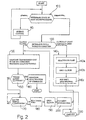
- Figure 2 illustrates a preferred example of the operation of the transmission control circuit 24 working in accordance with the present invention.
- a block 100 in which the auxiliary microprocessor 46 determines the state of operation of the main microprocessor 44, for example by monitoring a CLOCK signal CK from the main microprocessor 44.
- the block 100 is followed by a block 110, otherwise, in the event that a malfunctioning of the main microprocessor is determined, we go from block 100 to block 120.
- the state of malfunctioning can be determined, for example, in the event that the CLOCK signal is absent or irregular.
- Block 110 carries out, in a known manner, control of the transmission unit 10 via the main microprocessor 44 and on the basis of the signals G supplied to the circuit 24 (and possibly of the state of the engine 3 as determined from the data coming through the data line 29). From block 110 we return to block 100, although remaining within the loop formed by the blocks 100, 110 so long as the main microprocessor 44 is operating correctly.
- Block 120 transfers the control of the transmission unit 10 to the auxiliary microprocessor 46 and possibly generates a signal in order to execute a malfunctioning and danger signalling (optical, audible) addressed to the user of the vehicle (not illustrated).
- the auxiliary microprocessor 46 comprises a first data exchange interface 46a (illustrated in Figure 1) receiving the signals identifying the state of malfunctioning of the microprocessor 44 and a second data exchange interface 46b (illustrated in Figure 1) which is normally configured as an input interface (INPUT). With the determining of the state of malfunctioning the second interface 46b becomes configured as an output interface (OUTPUT) for the purpose of allowing the generation of control signals by the auxiliary microprocessor 46 heading for the transmission unit 10.
- the auxiliary microprocessor 46 determines a first and a second working condition of the vehicle by observation of the state of the clutch 15 as prevailing before the determining of the malfunctioning.
- the block 120 determines a first working condition in which the clutch 15 is closed and the vehicle is proceeding normally or is stationary and a second working condition in which the clutch 15 is at least partially open and a shift of gear or a pull-away is in progress.
- the first working condition is determined the block 120 is followed by a block 130, otherwise, in the event of the determining of the second working condition the block 120 is followed by a block 140.
- the determining of the state of the clutch 15 can be undertaken by sequentially storing the clutch control signal OP/CL generated by the main microprocessor 44 and retrieving the last stored value of this signal before the determining of the malfunctioning.
- the determining of the state of the clutch can be carried out by determining the actual position of the clutch 15, for example with a position sensor (not illustrated) or by determining the strength of the control current of the electric valve 32.
- the block 130 acts on the transmission unit 10 in order to maintain this unit in the working condition in use before the detection of the malfunctioning; in particular, the block 130 operates on the controls of the unit 10 in order to prevent the opening of the clutch 15 and the modifying of the currently set transmission ratio.
- the block 130 controls:
- Block 130 is followed by a block 150 which checks whether the speed of the vehicle is below a near-zero threshold value; if so (vehicle stationary or almost stationary) block 150 is followed by a block 160, otherwise (vehicle moving with non-negligible speed) block 150 is followed by a block 170.
- Block 160 maintains the deactivation of the controls of the transmission unit 10 as done in block 130 and possibly sends a malfunctioning signalling (for example of the optical or acoustic type) to the driver of the vehicle.
- Block 170 waits for the speed of the vehicle to drop below a preset threshold value corresponding to a safety speed; upon the reaching of this safety speed, we pass from block 170 to a block 180.
- block 170 may wait for the angular speed of the engine to drop below a preset threshold value corresponding to a safety rotation range; upon reaching this safety range, we pass from block 170 to block 180.
- Block 180 commands the closure of the relay 41 in order to reactivate the electric pump 35 and resupply the actuator units 19 and 21 with pressurized oil.
- Block 180 is followed by a block 190 which commands the supplying to the electric valve 32 of an electrical signal able to effect the opening of the clutch 15.
- Block 190 is followed by a block 200 which commands the supplying to the valve devices 39a, 39b of a signal able to effect the putting into neutral of the shift 17.
- Block 200 is followed by a wait block 210 (TIME OUT) which effects a closed loop for a preset: period of time T; on termination of the period T, we return from block 210 to block 130.
- TIME OUT wait block 210
- Block 140 comprises a block 140a which commands the closure of the relay 41 in order to reactivate the electric pump 35 (if deactivated by the faulty main microprocessor) and supply the actuator units 19 and 21 with pressurized oil.
- Block 140a is followed by a block 140b which commands the supplying to the electric valve 32 of an electrical signal able to effect the opening of the clutch 15.
- Block 140b is followed by a block 140c which sends the valve devices 39a, 39b a signal able to effect the putting into neutral of the shift 17. From block 140c we go to block 210.
- the malfunctioning of the main microprocessor 44 is immediately determined (block 100), transferring the control of the transmission unit 10 from the main microprocessor 44 (faulty) to the auxiliary microprocessor (block 120). Therefore, the state of the vehicle is monitored (block 120) and if the vehicle is stationary or is travelling along at normal speed, all the commands to the transmission unit 10 are removed (block 130) so as to prevent the vehicle from lacking traction (in the event that the vehicle is travelling along) or to prevent the starting of the vehicle (in the event that the vehicle is stationary).
Landscapes
- Engineering & Computer Science (AREA)
- General Engineering & Computer Science (AREA)
- Mechanical Engineering (AREA)
- Physics & Mathematics (AREA)
- Fluid Mechanics (AREA)
- Control Of Transmission Device (AREA)
- Selective Calling Equipment (AREA)
- Transmitters (AREA)
Description
- The present invention relates to a device and a method for transmission control.
- Control devices for vehicle transmission units are known, in which an electronic circuit supplies control signals for a first and a second actuator unit which are able to operate, respectively, the actuation of a clutch and the selection and engagement/disengagement of the gears of a shift associated with this clutch. The known electronic circuits comprise at least one microprocessor which generates the clutch and shift actuation signals on the basis of a plurality of input signals, for example representative of a manually selected gear, of the working conditions of the engine, etc.
- In the event of a malfunctioning of the microprocessor, the control signals may be completely lacking or may be generated in an entirely chance manner making the transmission unit unusable and giving rise, as a consequence, to the unmanageability of the vehicle. In particular, in the event of a malfunctioning of the microprocessor while the vehicle is travelling at high speed, any failing in traction due to the accidental opening of the clutch or to the accidental disengaging of the engaged gear, may give rise to the loss of control of the vehicle. Similar considerations may hold in the event of a malfunctioning of the microprocessor while the vehicle is travelling along a steeply descending stretch of road.
- The object of the present invention is to produce a transmission control device which overcomes the drawbacks of the known devices.
- Document GB-A-2 191 875 describes an electronic control device for a transmission unit as described in the preamble of claim 1.
- The above object is achieved by the present invention as the latter relates to a transmission control device of the type described in Claim 1. The present invention furthermore relates to a method of transmission control of the type described in Claim 13.
- The invention will now be illustrated with reference to the appended drawings which represent a preferred non-limiting embodiment in which:
- Figure 1 represents, schematically, an internal combustion engine of a vehicle coupled with a transmission unit cooperating with a transmission control device produced according to the dictates of the present invention;
- Figure 2 represents a logic diagram with operating blocks of the transmission control device of Figure 1.
- With particular reference to Figure 1, a transmission control device is indicated 1, as a whole, cooperating with an internal combustion engine 3, for example a petrol engine or a diesel engine. The engine 3 cooperates with an electronic engine-control facility 5 which receives as input a plurality of information parameters P measured mainly in the engine 3 and supplies control signals for the ignition system (not illustrated) and an injection system (not illustrated) of the engine 3.
- The engine 3 has an output shaft 8 able to provide mechanical power to the input of a
transmission unit 10 having anoutput shaft 12 able to transmit mechanical power to the wheels of a motor vehicle (not represented). Thetransmission unit 10 comprises aclutch 15 input-connected to the shaft 8 and a shift 17 input-connected to the output shaft of the saidclutch 15. Thetransmission unit 10 furthermore comprises a first actuator unit 19 (represented schematically) for opening and closing theclutch 15 and asecond actuator unit 21 for operating the selection and engagement/disengagement of the gears of the shift 17. - The
transmission unit 10 cooperates with atransmission control circuit 24 able to formulate a plurality of input signals G and able to control the first and thesecond actuator unit control circuit 24 can receive input signals from a manuallyactuatable selector device 26 usable for the selection of the gears. Thetransmission control circuit 24 furthermore cooperates with the engine control facility 5 to which it is connected via a bidirectional data transmission line (BUS) 29. - In particular, the
first actuator unit 19 comprises ahydraulic actuator 31 coupled with anelectric control valve 32 receiving pressurized oil from anelectric pump 35. Thehydraulic actuator 31 is able to actuate, in a known manner, theclutch 15, opening or closing theclutch 15 on the basis of an electrical control signal OP/CL supplied to theelectric valve 32 from thecircuit 24. Theactuator unit 21 comprises two double-actionhydraulic actuators 37a, 37b coupled with respectivecontrol valve devices 39a, 39b receiving pressurized oil from theelectric pump 35. Theactuator unit 21 is able, in a known manner and on the basis of a control signal GEAR supplied to thevalve device 39a, to engage/disengage the gears of the shift 17 and is furthermore able, in a known manner on the basis of a command SEL supplied to the valve device 39b, to select the setting of the gears of the shift 17. - The
transmission control circuit 24 furthermore controls arelay 41 for energizing theelectric pump 35. According to the present invention thetransmission control circuit 24 comprises afirst microprocessor 44 and anauxiliary microprocessor 46 working together according to the procedures which will be made clearer subsequently with the help of Figure 2. - Figure 2 illustrates a preferred example of the operation of the
transmission control circuit 24 working in accordance with the present invention. - To start with there is a
block 100 in which theauxiliary microprocessor 46 determines the state of operation of themain microprocessor 44, for example by monitoring a CLOCK signal CK from themain microprocessor 44. In the event that the monitored state of operation corresponds to normal operation of the main microprocessor 44 (for example in the event that the CLOCK signal is present and regular) theblock 100 is followed by ablock 110, otherwise, in the event that a malfunctioning of the main microprocessor is determined, we go fromblock 100 to block 120. The state of malfunctioning can be determined, for example, in the event that the CLOCK signal is absent or irregular. -
Block 110 carries out, in a known manner, control of thetransmission unit 10 via themain microprocessor 44 and on the basis of the signals G supplied to the circuit 24 (and possibly of the state of the engine 3 as determined from the data coming through the data line 29). Fromblock 110 we return toblock 100, although remaining within the loop formed by theblocks main microprocessor 44 is operating correctly. -
Block 120 transfers the control of thetransmission unit 10 to theauxiliary microprocessor 46 and possibly generates a signal in order to execute a malfunctioning and danger signalling (optical, audible) addressed to the user of the vehicle (not illustrated). Theauxiliary microprocessor 46 comprises a firstdata exchange interface 46a (illustrated in Figure 1) receiving the signals identifying the state of malfunctioning of themicroprocessor 44 and a seconddata exchange interface 46b (illustrated in Figure 1) which is normally configured as an input interface (INPUT). With the determining of the state of malfunctioning thesecond interface 46b becomes configured as an output interface (OUTPUT) for the purpose of allowing the generation of control signals by theauxiliary microprocessor 46 heading for thetransmission unit 10. - The
auxiliary microprocessor 46 determines a first and a second working condition of the vehicle by observation of the state of theclutch 15 as prevailing before the determining of the malfunctioning. In particular, theblock 120 determines a first working condition in which theclutch 15 is closed and the vehicle is proceeding normally or is stationary and a second working condition in which theclutch 15 is at least partially open and a shift of gear or a pull-away is in progress. In the event that the first working condition is determined theblock 120 is followed by ablock 130, otherwise, in the event of the determining of the second working condition theblock 120 is followed by ablock 140. The determining of the state of theclutch 15 can be undertaken by sequentially storing the clutch control signal OP/CL generated by themain microprocessor 44 and retrieving the last stored value of this signal before the determining of the malfunctioning. Alternatively, the determining of the state of the clutch can be carried out by determining the actual position of theclutch 15, for example with a position sensor (not illustrated) or by determining the strength of the control current of theelectric valve 32. - The
block 130 acts on thetransmission unit 10 in order to maintain this unit in the working condition in use before the detection of the malfunctioning; in particular, theblock 130 operates on the controls of theunit 10 in order to prevent the opening of theclutch 15 and the modifying of the currently set transmission ratio. - In particular, the
block 130 controls: - the opening of the
relay 41 so as to switch off theelectric pump 35 thereby disabling the supply of pressurized oil to theactuator units - the deactivation of the
electric valve 32 so as to disable thehydraulic actuator 31 thereby preventing the actuation of theclutch 15; and - the deactivation of the
valve devices 39a, 39b so as to disable the double-actionhydraulic actuators 37a, 37b thereby preventing the actuation of the shift 17 and in particular the disengaging of the gears. -
Block 130 is followed by ablock 150 which checks whether the speed of the vehicle is below a near-zero threshold value; if so (vehicle stationary or almost stationary)block 150 is followed by ablock 160, otherwise (vehicle moving with non-negligible speed)block 150 is followed by ablock 170.Block 160 maintains the deactivation of the controls of thetransmission unit 10 as done inblock 130 and possibly sends a malfunctioning signalling (for example of the optical or acoustic type) to the driver of the vehicle. - Block 170 waits for the speed of the vehicle to drop below a preset threshold value corresponding to a safety speed; upon the reaching of this safety speed, we pass from
block 170 to ablock 180. Alternatively,block 170 may wait for the angular speed of the engine to drop below a preset threshold value corresponding to a safety rotation range; upon reaching this safety range, we pass fromblock 170 to block 180. -
Block 180 commands the closure of therelay 41 in order to reactivate theelectric pump 35 and resupply theactuator units Block 180 is followed by ablock 190 which commands the supplying to theelectric valve 32 of an electrical signal able to effect the opening of theclutch 15.Block 190 is followed by ablock 200 which commands the supplying to thevalve devices 39a, 39b of a signal able to effect the putting into neutral of the shift 17.Block 200 is followed by a wait block 210 (TIME OUT) which effects a closed loop for a preset: period of time T; on termination of the period T, we return fromblock 210 to block 130. -
Block 140 comprises ablock 140a which commands the closure of therelay 41 in order to reactivate the electric pump 35 (if deactivated by the faulty main microprocessor) and supply theactuator units Block 140a is followed by ablock 140b which commands the supplying to theelectric valve 32 of an electrical signal able to effect the opening of theclutch 15.Block 140b is followed by ablock 140c which sends thevalve devices 39a, 39b a signal able to effect the putting into neutral of the shift 17. Fromblock 140c we go toblock 210. - In use, the malfunctioning of the
main microprocessor 44 is immediately determined (block 100), transferring the control of thetransmission unit 10 from the main microprocessor 44 (faulty) to the auxiliary microprocessor (block 120). Therefore, the state of the vehicle is monitored (block 120) and if the vehicle is stationary or is travelling along at normal speed, all the commands to thetransmission unit 10 are removed (block 130) so as to prevent the vehicle from lacking traction (in the event that the vehicle is travelling along) or to prevent the starting of the vehicle (in the event that the vehicle is stationary). In the event that the vehicle is travelling along at normal speed, the slowing down of the vehicle is awaited (block 170) in order to reactivate the electric pump 35 (block 180), open the clutch (block 190) and put the shift into neutral (block 200). Therefore, the shift is put into neutral at low speed without the danger that the lack of traction might cause the loss of control of the vehicle. Subsequently, the vehicle stops, for example because the driver has actuated the brakes, and is no longer able to set off again (block 130). In the event that the malfunctioning of the main microprocessor occurs during a gear shift or a pull-away (block 120), theelectric pump 35 is reactivated if it was switched off following the fault in the main microprocessor (block 140a). Following this, themicroprocessor 46 commands the opening of the clutch (block 140b) and places the shift into neutral (block 140c). - From the foregoing it is clear how the device which is the subject of the present invention enables the
transmission unit 10 to be placed in a safety condition following a fault in the main microprocessor. - Indeed, in the event of a fault, the following actions are possible:
- if the vehicle is stationary and the clutch is
closed (for example because the vehicle is stationary
with the engine switched off), the following are
prevented: the engaging or disengaging of the gears, the
opening of the clutch and the generating of hydraulic
power (blocks 130, 150, 160) and the consequent starting
of the vehicle with the
circuit 24 defective; - if the vehicle is moving and the clutch is
closed, traction is maintained so long as the speed of
the vehicle has not dropped below a safety threshold
(
blocks 130, 170) - this prevents lack of traction from being able to render the vehicle unmanageable; - if the vehicle is stationary and the clutch is open (for example while the vehicle is waiting at traffic lights), control of the pump is effected and so the clutch is opened and the shift put into neutral (block 140);
- if the vehicle is moving at low speed, the
clutch is opened and the shift is put into neutral
(
blocks - if a gear shift or a pull-away is being
operated, the shift is put into neutral (
blocks
Claims (16)
- Electronic control device of a transmission unit (10) comprising a clutch (15) receiving mechanical power from an internal combustion engine (3) and a gear shift (17) input-connected to an output of said clutch (15) and able to transfer mechanical power at the output (12) to the wheels of a vehicle, said transmission unit (10) furthermore comprising a first actuator unit (19) coupled to said clutch (15) and able to actuate the clutch, a second actuator unit (21) coupled to said shift (17) and able to carry out the selection and engagement/disengagement of the gears of the shift and electronic control means (24) supplying control signals for said first and second actuator units (19, 21) on the basis of information signals (G, 26, 29) supplied as input to the said electronic control means (24); said electronic control means (24) comprising at least one main microprocessor (44) able to formulate said control signals, said device further comprising auxiliary microprocessor means (46) able to determine a state of malfunctioning of said main microprocessor (44) in order to transfer the control of said transmission unit (10) to said auxiliary microprocessor means (46) in the event of the malfunctioning of said main microprocessor (44), andsaid auxiliary microprocessor means (46) comprise first means of examination (100) able to determine the state of operation of said main microprocessor (44); said first means of examination (100) being able to select second means of examination (120) in the event that the determined state of operation corresponds to a malfunctioning of said main microprocessor (44);said device is characterized in that said second means of examination (120) are able to determine at least a first and a second working condition of the vehicle by observation of the state of said clutch (15), as prevailing before detection of said malfunctioning;said clutch (15) being closed in said first working condition and being at least partially open in said second working condition;said second means of examination (120) are able to select first (130) or second (140) means of control, respectively, with the determining of said first or second working condition;said first means of control (130) being able to act on the transmission unit (10) in order to maintain this transmission unit (10) in the working condition in use before the detection of said malfunctioning.
- Device according to Claim 1, characterized in that the said first means of examination (100) are able to monitor a CLOCK signal (CK) from the main microprocessor (44) for the purpose of determining the said malfunctioning.
- Device according to Claim 1 or 2, characterized in that the said second means of examination (120) are able to store sequentially a clutch control signal (OP/CL) generated by the said main microprocessor (44) and are able to retrieve the last stored value of this signal (OP/CL) before the determining of the malfunctioning for the detection of the said first or second state.
- Device according to Claim 1, characterized in that the said first means of control (130) command the deactivation of generator means (35) of power for the said first and second actuator unit (19, 21).
- Device according to Claim 1, characterized in that the said first means of control (130) command:the deactivation of the said first actuator unit (19) in order to prevent the actuation of the said clutch; andthe deactivation of the said second actuator unit (21) in order to prevent the actuation of the said shift.
- Device according to one of the preceeding Claims, characterized in that the said first control means (130) select comparator means (150, 170) able to compare a parameter chosen from the speed of the vehicle and the number of engine revolutions with a first near-zero threshold value; the said comparator means (150, 170) being able to maintain (160) the transmission unit (10) in the working condition in use before the detection of the said malfunctioning in the event that the value of the said parameter is near to the said first threshold value.
- Device according to Claim 6, characterized in that the said comparator means (150, 170) are able to compare the said determined parameter with a second threshold value; the said comparator means being able to select uncoupling means (180, 190, 200) with the reaching of the said second threshold; said uncoupling means (180, 190, 200) being able to open the said clutch and put the said shift into neutral.
- Device according to Claim 7, characterized in that the said uncoupling means comprise:first redeployment means (180) able to operate the reactivation of the generator means (35) of power for the said first and second actuator unit (19, 21);first clutch control means (190) able to generate a control signal for the said first actuator unit (19) in order to open the said clutch (15); andfirst shift control means (200) able to generate a control signal for the said second actuator unit (21) in order to put the said shift (17) into neutral.
- Device according to one of the precceding Claims, characterized in that the said second control means (140) are able to open the said clutch and put the said shift into neutral.
- Device according to Claim 9, characterized in that the said second control means (140) comprise:second redeployment means (140a) able to operate the reactivation of generator means (35) of power for the said first and second actuator unit (19, 21);second clutch control means (140b) able to generate a control signal for the said first actuator unit (19) in order to open the said clutch (15); andsecond shift control means (140c) able to generate a control signal for the said second actuator unit (21) in order to put the said shift (17) into neutral.
- Device according to any one of the preceding claims, characterized in that the said auxiliary microprocessor means (46) comprise a first data exchange interface (46a) receiving signals identifying the said state of malfunctioning of the microprocessor and a second data exchange interface (46b) which is normally configured as an input interface (INPUT); with the determining of the said state of malfunctioning the said second interface (46b) being reconfigured as an output interface (OUTPUT) for the purpose of allowing the generation of control signals heading for the said transmission unit (10).
- Device according to any of the preceeding Claims, characterized in that the said second means of examination (120) are able to determine the state of the clutch via a position sensor.
- Method of control of a transmission unit (10) comprising a clutch (15) receiving mechanical power from an internal combustion engine (3) and a gear shift (17) input-connected to an output of said clutch (15) and able to transfer mechanical power at the output (12) to the wheels of a vehicle, said transmission unit (10) furthermore comprising a first actuator unit (19) coupled to said clutch (15) and able to actuate the clutch, a second actuator unit (21) coupled to said shift (17) and able to carry out the selection and engagement/disengagement of the gears of the shift and electronic control means (24) supplying control signals for said first and second actuator units (19, 21) on the basis of information signals (G, 26, 29) supplied as input to said electronic control means (24); said electronic control means (24) comprising at least one main microprocessor (44) able to formulate said control signals, the method further comprising the phase of determining (100) a state of malfunctioning of said main microprocessor (44); and the phase of transferring the control of said transmission unit (10) to auxiliary microprocessor means (46) in the event of the determining of said state of malfunctioning, said method is characterized in that it comprises the phase of determining at least a first and a second working condition of the vehicle by observation of the state of said clutch (15), as determined before detection of said malfunctioning;said clutch (15) being closed in said first working condition and being at least partially open in said second working condition;the determining of said first working condition is followed by the phase of acting on the transmission unit (10) for the purpose of maintaining this transmission unit (10) in the working condition in use before the detection of the said malfunctioning.
- Method according to Claim 13, characterized in that the said phase of acting on the said transmission unit comprises the following phases:deactivating the generator means (35) of power for the said first and second actuator unit (19, 21);deactivating the said first actuator unit (19) in order to prevent the actuation of the said clutch; anddeactivating the said second actuator unit (21) in order to prevent the actuation of the said shift.
- Method according to Claim 14, characterized in that the said phase of acting on the said transmission unit is followed by the phase of comparing the speed of the vehicle with a threshold value and, in the event that the said speed is below the said threshold, by the phase of opening the said clutch and putting the said shift into neutral.
- Method according to one of Claims 13 to 15, characterized in that the determining of the said second working condition is followed by the phase of opening the said clutch and putting the said shift into neutral.
Applications Claiming Priority (2)
| Application Number | Priority Date | Filing Date | Title |
|---|---|---|---|
| ITTO960242 | 1996-03-29 | ||
| IT96TO000242A IT1285045B1 (en) | 1996-03-29 | 1996-03-29 | DEVICE AND METHOD OF TRANSMISSION CONTROL |
Publications (2)
| Publication Number | Publication Date |
|---|---|
| EP0798497A1 EP0798497A1 (en) | 1997-10-01 |
| EP0798497B1 true EP0798497B1 (en) | 2001-07-18 |
Family
ID=11414493
Family Applications (1)
| Application Number | Title | Priority Date | Filing Date |
|---|---|---|---|
| EP97105056A Expired - Lifetime EP0798497B1 (en) | 1996-03-29 | 1997-03-25 | Device and method for transmission control |
Country Status (6)
| Country | Link |
|---|---|
| US (1) | US5908460A (en) |
| EP (1) | EP0798497B1 (en) |
| BR (1) | BR9700454A (en) |
| DE (1) | DE69705657T2 (en) |
| ES (1) | ES2161393T3 (en) |
| IT (1) | IT1285045B1 (en) |
Families Citing this family (16)
| Publication number | Priority date | Publication date | Assignee | Title |
|---|---|---|---|---|
| DE19810479A1 (en) * | 1998-03-11 | 1999-09-16 | Bayerische Motoren Werke Ag | Automatic transmission with electronic drive control for automobile |
| DE10030085A1 (en) * | 2000-06-19 | 2002-03-07 | Siemens Ag | Electronic transmission control |
| JP2002039366A (en) * | 2000-07-31 | 2002-02-06 | Toyota Motor Corp | Control device for vehicle transmission |
| ITBO20000626A1 (en) * | 2000-10-27 | 2002-04-27 | Magneti Marelli Spa | METHOD OF RETURNING THE ENGINE TORQUE DURING A GEAR SHIFT |
| US7912617B2 (en) * | 2005-12-14 | 2011-03-22 | Gm Global Technology Operations, Inc. | Air purge method for a rotating clutch |
| DE102007057104B3 (en) * | 2007-11-20 | 2009-07-30 | Getrag Getriebe- Und Zahnradfabrik Hermann Hagenmeyer Gmbh & Cie Kg | Drive train for a motor vehicle and method for securing a driving state |
| JP5546462B2 (en) | 2008-01-02 | 2014-07-09 | シェフラー テクノロジーズ アクチエンゲゼルシャフト ウント コンパニー コマンディートゲゼルシャフト | Clutch actuator and control method of clutch actuator |
| US8155847B2 (en) * | 2008-06-03 | 2012-04-10 | GM Global Technology Operations LLC | Electronic transmission shifting architecture with maximized availability |
| DE102009009999B4 (en) * | 2009-02-23 | 2012-09-13 | Getrag Getriebe- Und Zahnradfabrik Hermann Hagenmeyer Gmbh & Co. Kg | Clutch control method |
| DE102011010512A1 (en) * | 2010-02-18 | 2011-08-18 | Schaeffler Technologies GmbH & Co. KG, 91074 | Passive security circuit |
| FR2978407B1 (en) * | 2011-07-29 | 2013-08-09 | Peugeot Citroen Automobiles Sa | DEVICE FOR SECURELY MONITORING THE OPERATION OF A GEARBOX WITH TWO CLUTCHES, IN ACCORDANCE WITH AT LEAST THE ACTUAL POSITIONS OF THESE TWO CLUTCHES |
| DE102012003328A1 (en) | 2012-02-15 | 2013-08-22 | Getrag Getriebe- Und Zahnradfabrik Hermann Hagenmeyer Gmbh & Cie Kg | Method and control unit for a powertrain component |
| US9334948B2 (en) | 2013-03-07 | 2016-05-10 | GM Global Technology Operations LLC | Split electronic transmission range selection systems and methods with electronic button shifter |
| US8818655B1 (en) | 2013-03-07 | 2014-08-26 | GM Global Technology Operations LLC | Split electronic transmission range selection systems and methods |
| JP6624974B2 (en) * | 2016-03-03 | 2019-12-25 | 株式会社クボタ | Multipurpose vehicle |
| JP6733561B2 (en) * | 2017-01-17 | 2020-08-05 | トヨタ自動車株式会社 | Vehicle shift control device |
Family Cites Families (13)
| Publication number | Priority date | Publication date | Assignee | Title |
|---|---|---|---|---|
| US4872106A (en) * | 1983-04-06 | 1989-10-03 | New Forney Corp. | Industrial process control system with back-up data processors to take over from failed primary data processors |
| US4558416A (en) * | 1983-05-27 | 1985-12-10 | Allied Corporation | Method for maintaining the integrity of a dual microprocessor multiprocessing computing system |
| JPS62299435A (en) * | 1986-06-19 | 1987-12-26 | Isuzu Motors Ltd | Control device for vehicle with malfunction detecting device |
| DE3818007A1 (en) * | 1988-05-27 | 1989-12-07 | Renk Ag | ELECTRONIC CONTROL DEVICE FOR A DRIVE SYSTEM |
| JP2898045B2 (en) * | 1990-03-01 | 1999-05-31 | マツダ株式会社 | Operating device for automatic transmission for vehicles |
| JP2768791B2 (en) * | 1990-03-09 | 1998-06-25 | 三菱自動車工業株式会社 | Automotive electronic control unit |
| GB2242716B (en) * | 1990-03-28 | 1994-04-06 | Nissan Motor | Control apparatus with fail-safe faculty |
| US5418937A (en) * | 1990-11-30 | 1995-05-23 | Kabushiki Kaisha Toshiba | Master-slave type multi-processing system with multicast and fault detection operations having improved reliability |
| US5274554A (en) * | 1991-02-01 | 1993-12-28 | The Boeing Company | Multiple-voting fault detection system for flight critical actuation control systems |
| JPH05203036A (en) * | 1992-01-29 | 1993-08-10 | Mazda Motor Corp | Control device for vehicle |
| US5754780A (en) * | 1994-01-19 | 1998-05-19 | Tokyo Electron Limited | Apparatus and method for performing serial communication between master and slave devices |
| US5491787A (en) * | 1994-08-25 | 1996-02-13 | Unisys Corporation | Fault tolerant digital computer system having two processors which periodically alternate as master and slave |
| NO950617D0 (en) * | 1995-02-17 | 1995-02-17 | Kongsberg Automotive Technolog | Security |
-
1996
- 1996-03-29 IT IT96TO000242A patent/IT1285045B1/en active IP Right Grant
-
1997
- 1997-03-25 ES ES97105056T patent/ES2161393T3/en not_active Expired - Lifetime
- 1997-03-25 DE DE69705657T patent/DE69705657T2/en not_active Expired - Lifetime
- 1997-03-25 BR BR9700454A patent/BR9700454A/en not_active IP Right Cessation
- 1997-03-25 EP EP97105056A patent/EP0798497B1/en not_active Expired - Lifetime
- 1997-03-26 US US08/824,315 patent/US5908460A/en not_active Expired - Lifetime
Also Published As
| Publication number | Publication date |
|---|---|
| ITTO960242A1 (en) | 1997-09-29 |
| BR9700454A (en) | 1998-11-03 |
| DE69705657T2 (en) | 2002-05-23 |
| DE69705657D1 (en) | 2001-08-23 |
| ES2161393T3 (en) | 2001-12-01 |
| EP0798497A1 (en) | 1997-10-01 |
| ITTO960242A0 (en) | 1996-03-29 |
| IT1285045B1 (en) | 1998-06-03 |
| US5908460A (en) | 1999-06-01 |
Similar Documents
| Publication | Publication Date | Title |
|---|---|---|
| US5908460A (en) | Device and method for transmission control | |
| US4910494A (en) | Automotive vehicle control system | |
| KR100553783B1 (en) | vehicle. | |
| US20060155435A1 (en) | Method and system for controlling at least one actuator in the drive train of a motor vehicle | |
| JPH06174070A (en) | Transmission control system having limp-home function | |
| US8128530B2 (en) | Method for automatically controlling a neutral position and a parking lock of a motor vehicle transmission | |
| EP0809765B1 (en) | A safety system in a clutch management system, an electronic backup control unit and a method for control | |
| KR100521348B1 (en) | Transmission shifted to auxiliary lever | |
| GB2310261A (en) | Function-checking device for an actuator means | |
| JPH06105058B2 (en) | Ship | |
| EP0441290B1 (en) | Automatic transmission with sensor fault detector | |
| WO1999047836A1 (en) | Control methods for a shift by wire vehicle transmission | |
| US20110294622A1 (en) | Control apparatus for a vehicle | |
| EP0611345B1 (en) | A clutch control system | |
| CN113324024B (en) | Controls for shift-by-wire systems | |
| PL211869B1 (en) | Driveline torque interrupt system | |
| GB2315836A (en) | Automatic clutch having a control device which activates an emergency routine | |
| KR100212424B1 (en) | Clutch control | |
| JP7845090B2 (en) | Engine start control device | |
| JP5234309B2 (en) | Shift control device | |
| EP0550447B1 (en) | A method for controlling an internal combustion engine fitted in a motor vehicle | |
| RU2374092C1 (en) | System to control electropneumatic drive of stepped gearbox | |
| JPH0645392Y2 (en) | Power take-out control device for work vehicle | |
| JPS62122826A (en) | Vehicle control device | |
| JPH056063B2 (en) |
Legal Events
| Date | Code | Title | Description |
|---|---|---|---|
| PUAI | Public reference made under article 153(3) epc to a published international application that has entered the european phase |
Free format text: ORIGINAL CODE: 0009012 |
|
| AK | Designated contracting states |
Kind code of ref document: A1 Designated state(s): DE ES FR GB SE |
|
| 17P | Request for examination filed |
Effective date: 19970923 |
|
| 17Q | First examination report despatched |
Effective date: 19991126 |
|
| GRAG | Despatch of communication of intention to grant |
Free format text: ORIGINAL CODE: EPIDOS AGRA |
|
| GRAG | Despatch of communication of intention to grant |
Free format text: ORIGINAL CODE: EPIDOS AGRA |
|
| GRAH | Despatch of communication of intention to grant a patent |
Free format text: ORIGINAL CODE: EPIDOS IGRA |
|
| GRAH | Despatch of communication of intention to grant a patent |
Free format text: ORIGINAL CODE: EPIDOS IGRA |
|
| GRAA | (expected) grant |
Free format text: ORIGINAL CODE: 0009210 |
|
| AK | Designated contracting states |
Kind code of ref document: B1 Designated state(s): DE ES FR GB SE |
|
| REF | Corresponds to: |
Ref document number: 69705657 Country of ref document: DE Date of ref document: 20010823 |
|
| RAP2 | Party data changed (patent owner data changed or rights of a patent transferred) |
Owner name: MAGNETI MARELLI POWERTRAIN S.P.A. |
|
| REG | Reference to a national code |
Ref country code: ES Ref legal event code: FG2A Ref document number: 2161393 Country of ref document: ES Kind code of ref document: T3 |
|
| ET | Fr: translation filed | ||
| REG | Reference to a national code |
Ref country code: GB Ref legal event code: IF02 |
|
| PLBE | No opposition filed within time limit |
Free format text: ORIGINAL CODE: 0009261 |
|
| STAA | Information on the status of an ep patent application or granted ep patent |
Free format text: STATUS: NO OPPOSITION FILED WITHIN TIME LIMIT |
|
| 26N | No opposition filed | ||
| REG | Reference to a national code |
Ref country code: FR Ref legal event code: PLFP Year of fee payment: 20 |
|
| PGFP | Annual fee paid to national office [announced via postgrant information from national office to epo] |
Ref country code: DE Payment date: 20160218 Year of fee payment: 20 Ref country code: ES Payment date: 20160304 Year of fee payment: 20 |
|
| PGFP | Annual fee paid to national office [announced via postgrant information from national office to epo] |
Ref country code: FR Payment date: 20160219 Year of fee payment: 20 Ref country code: SE Payment date: 20160219 Year of fee payment: 20 Ref country code: GB Payment date: 20160223 Year of fee payment: 20 |
|
| REG | Reference to a national code |
Ref country code: DE Ref legal event code: R071 Ref document number: 69705657 Country of ref document: DE |
|
| REG | Reference to a national code |
Ref country code: GB Ref legal event code: PE20 Expiry date: 20170324 |
|
| REG | Reference to a national code |
Ref country code: SE Ref legal event code: EUG |
|
| PG25 | Lapsed in a contracting state [announced via postgrant information from national office to epo] |
Ref country code: GB Free format text: LAPSE BECAUSE OF EXPIRATION OF PROTECTION Effective date: 20170324 |
|
| REG | Reference to a national code |
Ref country code: ES Ref legal event code: FD2A Effective date: 20170630 |
|
| PG25 | Lapsed in a contracting state [announced via postgrant information from national office to epo] |
Ref country code: ES Free format text: LAPSE BECAUSE OF EXPIRATION OF PROTECTION Effective date: 20170326 |