EP0798113B1 - Method and apparatus for producing panels - Google Patents
Method and apparatus for producing panels Download PDFInfo
- Publication number
- EP0798113B1 EP0798113B1 EP19970400679 EP97400679A EP0798113B1 EP 0798113 B1 EP0798113 B1 EP 0798113B1 EP 19970400679 EP19970400679 EP 19970400679 EP 97400679 A EP97400679 A EP 97400679A EP 0798113 B1 EP0798113 B1 EP 0798113B1
- Authority
- EP
- European Patent Office
- Prior art keywords
- centre
- station
- rebate
- fact
- gluing
- Prior art date
- Legal status (The legal status is an assumption and is not a legal conclusion. Google has not performed a legal analysis and makes no representation as to the accuracy of the status listed.)
- Expired - Lifetime
Links
Images


Classifications
-
- B—PERFORMING OPERATIONS; TRANSPORTING
- B32—LAYERED PRODUCTS
- B32B—LAYERED PRODUCTS, i.e. PRODUCTS BUILT-UP OF STRATA OF FLAT OR NON-FLAT, e.g. CELLULAR OR HONEYCOMB, FORM
- B32B37/00—Methods or apparatus for laminating, e.g. by curing or by ultrasonic bonding
- B32B37/14—Methods or apparatus for laminating, e.g. by curing or by ultrasonic bonding characterised by the properties of the layers
- B32B37/146—Methods or apparatus for laminating, e.g. by curing or by ultrasonic bonding characterised by the properties of the layers whereby one or more of the layers is a honeycomb structure
-
- B—PERFORMING OPERATIONS; TRANSPORTING
- B31—MAKING ARTICLES OF PAPER, CARDBOARD OR MATERIAL WORKED IN A MANNER ANALOGOUS TO PAPER; WORKING PAPER, CARDBOARD OR MATERIAL WORKED IN A MANNER ANALOGOUS TO PAPER
- B31D—MAKING ARTICLES OF PAPER, CARDBOARD OR MATERIAL WORKED IN A MANNER ANALOGOUS TO PAPER, NOT PROVIDED FOR IN SUBCLASSES B31B OR B31C
- B31D3/00—Making articles of cellular structure, e.g. insulating board
- B31D3/02—Making articles of cellular structure, e.g. insulating board honeycombed structures, i.e. the cells having an essentially hexagonal section
- B31D3/0284—Laminating honeycomb cores; applying cover sheets to core edges; working core edges
-
- Y—GENERAL TAGGING OF NEW TECHNOLOGICAL DEVELOPMENTS; GENERAL TAGGING OF CROSS-SECTIONAL TECHNOLOGIES SPANNING OVER SEVERAL SECTIONS OF THE IPC; TECHNICAL SUBJECTS COVERED BY FORMER USPC CROSS-REFERENCE ART COLLECTIONS [XRACs] AND DIGESTS
- Y10—TECHNICAL SUBJECTS COVERED BY FORMER USPC
- Y10T—TECHNICAL SUBJECTS COVERED BY FORMER US CLASSIFICATION
- Y10T156/00—Adhesive bonding and miscellaneous chemical manufacture
- Y10T156/10—Methods of surface bonding and/or assembly therefor
- Y10T156/1002—Methods of surface bonding and/or assembly therefor with permanent bending or reshaping or surface deformation of self sustaining lamina
- Y10T156/1003—Methods of surface bonding and/or assembly therefor with permanent bending or reshaping or surface deformation of self sustaining lamina by separating laminae between spaced secured areas [e.g., honeycomb expanding]
-
- Y—GENERAL TAGGING OF NEW TECHNOLOGICAL DEVELOPMENTS; GENERAL TAGGING OF CROSS-SECTIONAL TECHNOLOGIES SPANNING OVER SEVERAL SECTIONS OF THE IPC; TECHNICAL SUBJECTS COVERED BY FORMER USPC CROSS-REFERENCE ART COLLECTIONS [XRACs] AND DIGESTS
- Y10—TECHNICAL SUBJECTS COVERED BY FORMER USPC
- Y10T—TECHNICAL SUBJECTS COVERED BY FORMER US CLASSIFICATION
- Y10T156/00—Adhesive bonding and miscellaneous chemical manufacture
- Y10T156/10—Methods of surface bonding and/or assembly therefor
- Y10T156/1002—Methods of surface bonding and/or assembly therefor with permanent bending or reshaping or surface deformation of self sustaining lamina
- Y10T156/1026—Methods of surface bonding and/or assembly therefor with permanent bending or reshaping or surface deformation of self sustaining lamina with slitting or removal of material at reshaping area prior to reshaping
-
- Y—GENERAL TAGGING OF NEW TECHNOLOGICAL DEVELOPMENTS; GENERAL TAGGING OF CROSS-SECTIONAL TECHNOLOGIES SPANNING OVER SEVERAL SECTIONS OF THE IPC; TECHNICAL SUBJECTS COVERED BY FORMER USPC CROSS-REFERENCE ART COLLECTIONS [XRACs] AND DIGESTS
- Y10—TECHNICAL SUBJECTS COVERED BY FORMER USPC
- Y10T—TECHNICAL SUBJECTS COVERED BY FORMER US CLASSIFICATION
- Y10T156/00—Adhesive bonding and miscellaneous chemical manufacture
- Y10T156/12—Surface bonding means and/or assembly means with cutting, punching, piercing, severing or tearing
-
- Y—GENERAL TAGGING OF NEW TECHNOLOGICAL DEVELOPMENTS; GENERAL TAGGING OF CROSS-SECTIONAL TECHNOLOGIES SPANNING OVER SEVERAL SECTIONS OF THE IPC; TECHNICAL SUBJECTS COVERED BY FORMER USPC CROSS-REFERENCE ART COLLECTIONS [XRACs] AND DIGESTS
- Y10—TECHNICAL SUBJECTS COVERED BY FORMER USPC
- Y10T—TECHNICAL SUBJECTS COVERED BY FORMER US CLASSIFICATION
- Y10T156/00—Adhesive bonding and miscellaneous chemical manufacture
- Y10T156/17—Surface bonding means and/or assemblymeans with work feeding or handling means
- Y10T156/1702—For plural parts or plural areas of single part
- Y10T156/1712—Indefinite or running length work
-
- Y—GENERAL TAGGING OF NEW TECHNOLOGICAL DEVELOPMENTS; GENERAL TAGGING OF CROSS-SECTIONAL TECHNOLOGIES SPANNING OVER SEVERAL SECTIONS OF THE IPC; TECHNICAL SUBJECTS COVERED BY FORMER USPC CROSS-REFERENCE ART COLLECTIONS [XRACs] AND DIGESTS
- Y10—TECHNICAL SUBJECTS COVERED BY FORMER USPC
- Y10T—TECHNICAL SUBJECTS COVERED BY FORMER US CLASSIFICATION
- Y10T83/00—Cutting
- Y10T83/02—Other than completely through work thickness
- Y10T83/0304—Grooving
- Y10T83/0311—By use of plural independent rotary blades
-
- Y—GENERAL TAGGING OF NEW TECHNOLOGICAL DEVELOPMENTS; GENERAL TAGGING OF CROSS-SECTIONAL TECHNOLOGIES SPANNING OVER SEVERAL SECTIONS OF THE IPC; TECHNICAL SUBJECTS COVERED BY FORMER USPC CROSS-REFERENCE ART COLLECTIONS [XRACs] AND DIGESTS
- Y10—TECHNICAL SUBJECTS COVERED BY FORMER USPC
- Y10T—TECHNICAL SUBJECTS COVERED BY FORMER US CLASSIFICATION
- Y10T83/00—Cutting
- Y10T83/647—With means to convey work relative to tool station
- Y10T83/6584—Cut made parallel to direction of and during work movement
- Y10T83/6587—Including plural, laterally spaced tools
Definitions
- the pressing station 40 consists of two wide belts 52 (the width of the panels) mounted between rollers 54. Pressing means 56, possibly heating for activate the glue, press the two plates 13 on either side of the sheet median 14 on the glued edges, to complete the formation of the panels.
Abstract
Description
L'invention se rapporte à un procédé de fabrication de panneaux composites dits « sandwich » dans lesquels deux plaques ou feuilles sont collées de part et d'autre d'une nappe médiane à alvéoles transversales, constituée d'un réseau de bandes de largeur constante définissant lesdites alvéoles. L'invention s'applique avantageusement à la mise en oeuvre d'un procédé dans lequel ladite nappe médiane peut se présenter d'abord à l'état contracté, lesdites bandes sensiblement jointives, puis être déployée pour faire apparaítre lesdites alvéoles. Ces dernières sont de préférence à contour hexagonal, du type nid d'abeilles. L'invention concerne aussi une machine pour la mise en oeuvre du procédé.The invention relates to a process for manufacturing so-called “sandwich” composite panels. in which two plates or sheets are glued on either side of a middle ply to transverse cells, consisting of a network of bands of constant width defining said cells. The invention advantageously applies to the implementation of a method wherein said central ply can first appear in the contracted state, said strips substantially contiguous, and then be deployed to reveal said cells. These last are preferably hexagonal in outline, of the honeycomb type. The invention also relates to a machine for carrying out the process.
La structure décrite ci-dessus d'un panneau composite dit « sandwich » est connue, sa fabrication pose des problèmes. En particulier, ladite nappe médiane est difficile à manipuler et à positionner en raison de sa déformabilité. Un procédé connu consiste à déployer une nappe médiane aux dimensions d'un panneau, de façon à former des alvéoles aussi régulières que possibles, à encoller séparément et uniformément deux plaques et à les appliquer de part et d'autre de ladite nappe, sur les chants desdites alvéoles. Les plaques encollées sont difficiles à manipuler. Il est nécessaire de les appliquer l'une après l'autre sur ladite nappe médiane. La consommation de colle est importante.The structure described above of a so-called “sandwich” composite panel is known, its manufacturing poses problems. In particular, said middle ply is difficult to handle and to position due to its deformability. A known method consists in deploying a sheet median to the dimensions of a panel, so as to form cells as regular as possible, to glue two plates separately and uniformly and to apply them on both sides on the other side of said ply, on the edges of said cells. Glued plates are difficult to manipulate. It is necessary to apply them one after the other on said central ply. The consumption of glue is important.
L'invention permet de supprimer tous ces inconvénients.The invention eliminates all these drawbacks.
Plus précisément, l'invention concerne un procédé de fabrication de panneaux consistant à coller des plaques ou feuilles de part et d'autre d'une nappe médiane à alvéoles transversales, constituée d'un réseau de bandes de largeur constante définissant lesdites alvéoles, caractérisée en ce qu'il consiste à encoller les chants de ces bandes définissant ledit réseau, de part et d'autre de ladite nappe et à appliquer lesdites plaques ou feuilles sur ces chants encollés.More specifically, the invention relates to a method of manufacturing panels consisting of sticking plates or sheets on either side of a median sheet with transverse cells, consisting of a network of bands of constant width defining said cells, characterized in that it consists in gluing the edges of these bands defining said network, on the one hand and on the other side of said sheet and to apply said plates or sheets to these glued edges.
Selon une caractéristique avantageuse de l'invention, on effectue l'opération consistant à encoller lesdits chants des bandes, lorsque ladite nappe médiane est à l'état contracté, lesdites bandes étant sensiblement jointives et on déploie ensuite ladite nappe médiane pour faire apparaítre les alvéoles avant d'y appliquer lesdites plaques ou feuilles. L'encollage des chants se fait ainsi dans les meilleures conditions avec une consommation minimum de colle.According to an advantageous characteristic of the invention, the operation consisting of gluing said edges of the bands, when said central ply is in the contracted state, said bands being substantially contiguous and then deploying said middle ply to make appear the cells before applying said plates or sheets. Gluing the edges is done in the best conditions with a minimum consumption of glue.
Selon une caractéristique essentielle de l'invention, on pratique deux rainures latérales parallèles dans l'épaisseur des bords longitudinaux de ladite nappe médiane avant son déploiement et on utilise ces rainures pour le guidage de ladite nappe. Ainsi, cette dernière est supportée et maintenue dans son propre plan, sans avoir à reposer sur une surface plane. L'encollage peut se faire sur toute la surface, notamment les bords et simultanément sur les deux faces. Les plaques ou feuilles peuvent aussi être appliquées simultanément sur les deux faces encollées de la nappe. Cette particularité permet donc une production industrielle pratiquement en continu.According to an essential characteristic of the invention, two lateral grooves are practiced parallel in the thickness of the longitudinal edges of said central ply before its deployment and these grooves are used for guiding said sheet. So the latter is supported and maintained in its own plane, without having to rest on a flat surface. Gluing can be done over the entire surface, especially the edges and simultaneously on the two sides. Plates or sheets can also be applied simultaneously on both glued sides of the tablecloth. This particularity therefore allows industrial production practically continuously.
L'invention concerne aussi une machine de fabrication de panneaux comprenant une nappe médiane à alvéoles transversales constituée d'un réseau de bandes de largeur constante, de part et d'autre de laquelle sont collées des plaques ou feuilles, caractérisée en ce qu'elle comprend des unités de déplacement de ladite nappe et en ce que le long de ces unités de déplacement sont agencés, suivant le sens de progression de la nappe, un poste d'encollage des chants desdites bandes et un poste d'application desdites plaques ou feuilles sur lesdits chants encollés.The invention also relates to a machine for manufacturing panels comprising a sheet median with transverse cells consisting of a network of bands of constant width, on both sides and on the other of which are stuck plates or sheets, characterized in that it comprises displacement units of said tablecloth and in that along these displacement units are arranged, according to the direction of progression of the sheet, a station for gluing the edges said strips and a station for applying said plates or sheets to said edges glued.
L'invention sera mieux comprise à la lumière de la description qui va suivre de machines de fabrication en continu de panneaux mettant en oeuvre le principe de l'invention, donnée à titre d'exemple et faite en référence aux dessins annexés dans lesquels :
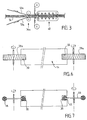
- La figure 1 représente schématiquement, en élévation, le principe d'une machine de fabrication de panneaux composites, conforme à l'invention ;
- la figure 2 est une vue de dessus de la figure 1 ;
- la figure 3 est une vue partielle en élévation, analogue à la figure 1, illustrant une variante de la machine ;
- la figure 4 est une vue de dessus, à plus grande échelle, du poste de déploiement de la nappe médiane ;
- la figure 5 est une coupe V-V de la figure 5 ;
- la figure 6 est une coupe VI-VI, à plus grande échelle, de la figure 2 ; et
- la figure 7 est une coupe VII-VII, à plus grande échelle, de la figure 2.
- Figure 1 shows schematically, in elevation, the principle of a machine for manufacturing composite panels, according to the invention;
- Figure 2 is a top view of Figure 1;
- Figure 3 is a partial elevational view, similar to Figure 1, illustrating a variant of the machine;
- Figure 4 is a top view, on a larger scale, of the deployment station of the middle ply;
- Figure 5 is a section VV of Figure 5;
- Figure 6 is a section VI-VI, on a larger scale, of Figure 2; and
- FIG. 7 is a section VII-VII, on a larger scale, of FIG. 2.
En se reportant aux dessins, on distingue les principaux éléments d'une machine de fabrication
11 de panneaux 12 à structure composite. Selon l'exemple des figures 1 et 2, ces panneaux
sont constitués de l'assemblage d'une nappe médiane 14 à alvéoles transversales (s'étendant ici
verticalement suivant l'épaisseur de la nappe) et de deux plaques 13 collées de part et d'autre
de la nappe médiane. Cette dernière se présente sous la forme d'une large plaque continue 15,
épaisse, constituée par un réseau de bandes 16 de largeur constante, susceptibles de définir des
alvéoles transversales 18, ici à contour hexagonal dit « nid d'abeilles ».Referring to the drawings, we distinguish the main elements of a manufacturing machine
11 of
La largeur des bandes 16 définit l'épaisseur de ladite large plaque continue 15. Plus
précisément, ces bandes 16, par exemple en carton, sont collées côte à côte sur des segments
de longueur prédéterminée espacés d'une distance double. Cette nappe peut donc se présenter
à l'état contracté lorsque toutes les bandes sont accolées les unes contre les autres, formant un
ensemble compact, ou bien être déployée suivant une direction prédéterminée, ici la direction
longitudinale de la machine, jusqu'à former des alvéoles en nid d'abeilles. Ce déploiement est
notamment visible sur la figure 4 : il s'accompagne d'une réduction de la largeur de la nappe
14 dans la direction perpendiculaire à la direction de déploiement. La machine 11 est adaptée
pour faire progresser une telle nappe médiane 14 dans son propre « plan » d'abord à l'état
contracté, lesdites bandes 16 étant toutes parallèles et côte à côte, puis à l'état déployé,
lesdites bandes 16 définissant entre elles les alvéoles 18. Il ressort clairement de ce qui précède
que les chants desdites bandes, c'est-à-dire aussi les chants des extrémités des alvéoles 18, se
situent dans deux plans parallèles P1 et P2 où l'on vient coller les plaques 13 pour former un
panneau rigide. La machine 11 comprend des unités de déplacement 20, 21, 22 de cette nappe
continue, pour la faire progresser longitudinalement d'un poste de traitement à un autre. Le
sens de progression est de gauche à droite, en considérant les figures 1 et 2. L'unité de
déplacement 20 est constituée de deux courroies plates 25 de la largeur de la machine,
entraínées par des rouleaux 26 eux-mêmes entraínés par un moteur électrique non représenté.
Elle permet d'entraíner la nappe médiane 14 à l'état contracté. Les autres unités de
déplacement de la nappe médiane 14 seront décrites plus loin.The width of the strips 16 defines the thickness of said large
Globalement, la machine comporte (successivement ou d'amont en val en considérant le sens
de progression de la nappe médiane 14) un poste de fraisage 28 pour pratiquer deux rainures
latérales 30, un poste d'encollage 32, pour encoller les chants des alvéoles de la nappe 14
(dans les plans P1 et P2), un poste de déploiement 34 de la nappe 14, un poste d'application
36 des plaques 13, un poste de déroulement d'un film de protection 38, un poste de pressage
40 et un poste de sectionnement transversal 42.Overall, the machine comprises (successively or upstream in val by considering the direction
progression of the middle ply 14) a
Le poste de fraisage 28 est agencé au voisinage de l'unité d'entraínement 20 mentionnée ci-dessus.
Il comporte deux fraises 28a espacées de chaque côté de la nappe 14 et positionnées
pour pratiquer les deux rainures latérales 30 dans l'épaisseur des bords longitudinaux de la
nappe médiane 14. Les rainures 30 sont pratiquées lorsque la nappe est à l'état contracté
puisque le poste de déploiement se trouve en aval. Le poste d'encollage 32 se trouve
avantageusement en amont du poste de déploiement 34 et en aval du poste de fraisage 28.
L'encollage se fait ainsi sur les chants des bandes constituant la nappe médiane 14, celle-ci
étant à l'état contracté. La colle est ici appliquée sur toute la largeur de la nappe en défilement.
On obtient ainsi un encollage total des chants avec une relativement faible quantité de colle.The
Les unités de déplacement 21 et 22 mentionnées ci-dessus coopèrent avec les rainures 30 pour
maintenir la nappe 14 dans son « plan » et la déplacer longitudinalement sans autre support
plan jusqu'au poste de pressage 40, tout en dégageant ses bords, ce qui permet un encollage
total des chants des alvéoles. L'encollage pourrait néanmoins être partiel, en bandes, en lignes
ou en plots. L'unité de déplacement 21 ou 22 comporte deux courroies d'entraínement 45 de
chaque côté de la nappe 14. Chacune est montée entre deux poulies 46 et engagée sur une
certaine longueur dans les rainures 30 le long de certains tronçons de la nappe. L'une des
poulies de chaque courroie est motrice et actionnée par un moteur électrique non représenté.
Ainsi, l'unité de déplacement 21 est agencée au voisinage du poste d'encollage 32, tandis que
l'unité de déplacement 32 est agencée au voisinage du poste d'application 36 des plaques 13.
Chaque courroie 45 en matériau élastomère a une section sensiblement circulaire et comporte
une rainure dans laquelle s'engagent les poulies 46. Celles-ci sont plates et peuvent ainsi
s'engager dans la rainure 30 (voir figure 7). Une unité de guidage 48 semblable à l'unité de
déplacement 21 ou 22, mais sans moteur, est agencée au voisinage du poste de pressage 40. Il
est à noter que, pour ne pas surcharger les dessins, l'unité d'entraínement 20, le poste
d'encollage 32, le poste d'application 36, le poste de pressage 40 et le poste de sectionnement
42, ne sont visibles que sur la figure 1, tandis que les unités de déplacement 21, 22 et 23 et
l'unité de guidage 48, ne sont visibles que sur la figure 2.The
Le poste de déploiement 34 se compose essentiellement de deux guides latéraux 50 à section
en T, coplanaires et convergeant l'un vers l'autre (voir figures 2, 4 et 5). Ils s'étendent entre
les unités de déplacement 21 et 22. Ces guides 50 sont engagés dans les rainures 30 de la
nappe 14. Ils sont ainsi conformés et orientés pour imposer un rétrécissement de la nappe 14
lorsque celle-ci se déplace horizontalement . Le rétrécissement entraíne la formation
automatique des alvéoles 18.The
Le poste de pressage 40 se compose de deux larges courroies 52 (de la largeur des panneaux)
montées entre des rouleaux 54. Des moyens de pressage 56, éventuellement chauffants pour
activer la colle, permettent de presser les deux plaques 13 de part et d'autre de la nappe
médiane 14 sur les chants encollés, pour achever la formation des panneaux.The
Dans la variante de la figure 3, les plaques 13 sont remplacées par des feuilles 13a relativement
plus souples et qui peuvent être déroulées et appliquées en continu de part et d'autre de la
nappe 14. Le poste d'application en continu 36a se substitue donc au poste d'application de la
figure 1. Le poste de pressage 40 n'est pas modifié ; les autres postes, non visibles sur la figure
3 sont semblables à ceux du mode de réalisation précédemment décrit.In the variant of FIG. 3, the
On remarque que la nappe 14 est entièrement maintenue et guidée grâce à ses rainures 30.
Dans un premier temps, les guides sont parallèles et leur écartement correspond à la largeur de
la nappe à l'état contracté. Puis les guides se rapprochent progressivement provoquant le
déploiement des alvéoles. Enfin, les guides redeviennent parallèles et leur écartement
correspond à la largeur des panneaux.It is noted that the
Le fonctionnement de la machine qui vient d'être décrite constitue une mise en oeuvre possible
du procédé défini ci-dessus. Cependant, il est possible d'encoller les chants des alvéoles 18
après déploiement de la nappe 14.The operation of the machine which has just been described constitutes a possible implementation.
of the process defined above. However, it is possible to glue the edges of the
Claims (11)
- A process of manufacture of panels consisting of the gluing on both sides of a centre sheet (14) with transverse hexagonal cells, plates (13) or sheets (13a), consisting of a network of strips of constant width, which delimit the said hexagonal cells, consisting in particular in gluing the narrow ends (32), which delimit the said network on both sides of the said centre rebate and in applying the said plates or sheets on these glued-on narrow ends, characterised by the fact that it consists in cutting two parallel lateral grooves (30) in the thickness of the longitudinal edges of the said centre sheet (14) before it is deployed, when it is in contracted state and in using the said grooves for guiding the said centre sheet.
- A process of manufacture according to Claim 1 characterised by the fact of implementing the deployment, which engages the said rebate between two converging lateral guides (50), which are engaged in the said lateral grooves.
- A process according to Claim 1 or 2, characterised by the fact that an aforementioned centre rebate is formed with hexagonal cells (18) in the form of a bees' honeycomb.
- A process according to Claim 1, characterised by the fact that the grooves are reformed before gluing.
- A process according to the preceding Claims, characterised by the fact that an operation is performed which consists of gluing the said narrow ends of strips when the said centre rebate (14) is in contracted state, the said strips being almost contiguous and by the fact the said centre rebate is then deployed so as to reveal the said hexagonal cells prior to applying the said plates (13) or sheets (13a) to them.
- A panel manufacturing machine comprising a centre sheet (14) with transverse hexagonal cells constituting a network of strips of constant width, on both sides of which are glued plates (13) or sheets (13a) comprising transfer units (20, 21, 22) of the said centre rebate and along these transfer units, a gluing station (39) for gluing the narrow ends of the said strips, an application station (36) for the application of the said plates or sheets on the said narrow ends, to which adhesive has been applied and a deployment station (34) of the said centre rebate where it passes from a contracted state with the said almost continuous strips into a deployed state, revealing the said hexagonal cells, characterised by he fact that it comprises a milling station (28) for cutting the two lateral grooves (30) in the thickness of the longitudinal edges of the said centre rebate, arranged upstream of the said deployment station (34) with respect to the direction of movement of the said sheet and by the fact that the aforementioned transfer units (21,22) cooperate with these grooves.
- A machine according to Claim 6, characterised by the fact that the said deployment station (34) comprises two mutually converging lateral guides (50) and extending over a predetermined length, the said guides becoming engaged in the said grooves of the centre rebate.
- A machine according to Claim 6, characterised by the fact that an aforementioned transfer unit (21.22) comprises driving belts (45) fitted on pulleys and engaged in the said grooves along certain sections of the passage of the said centre rebate, certain of the pulleys being driving pulleys.
- A machine according to one of the Claims from 6 to 8, characterised by the fact that it comprises an individual plate application station (36) for the application of such plates on both sides of the said centre sheet and a pressing station (40) arranged in turn downstream of the said deployment station, with respect to the direction of movement of the said centre rebate.
- A machine according to one of he Claims from 6 to 8, characterised by the fact that it comprises a continuous application station (36a) for the application of such sheets on both sides of the centre rebate and a pressing station (40) arranged in turn downstream of the of the said deployment station, with respect to the direction of movement of the said centre rebate.
- A machine according to one of the foregoing Claims, characterised by the fact that the said gluing station (32) is located upstream of the said deployment station with respect to the direction of movement of the said centre rebate.
Applications Claiming Priority (2)
| Application Number | Priority Date | Filing Date | Title |
|---|---|---|---|
| FR9603796 | 1996-03-27 | ||
| FR9603796A FR2746703B1 (en) | 1996-03-27 | 1996-03-27 | METHOD AND MACHINE FOR MANUFACTURING PANELS |
Publications (2)
| Publication Number | Publication Date |
|---|---|
| EP0798113A1 EP0798113A1 (en) | 1997-10-01 |
| EP0798113B1 true EP0798113B1 (en) | 2004-02-18 |
Family
ID=9490585
Family Applications (1)
| Application Number | Title | Priority Date | Filing Date |
|---|---|---|---|
| EP19970400679 Expired - Lifetime EP0798113B1 (en) | 1996-03-27 | 1997-03-26 | Method and apparatus for producing panels |
Country Status (5)
| Country | Link |
|---|---|
| US (1) | US5975180A (en) |
| EP (1) | EP0798113B1 (en) |
| AT (1) | ATE259715T1 (en) |
| DE (1) | DE69727607T2 (en) |
| FR (1) | FR2746703B1 (en) |
Families Citing this family (9)
| Publication number | Priority date | Publication date | Assignee | Title |
|---|---|---|---|---|
| KR100244198B1 (en) * | 1997-12-09 | 2000-02-01 | 윤종용 | Air interference measurement set of base stations and method thereof |
| DE10313055B4 (en) * | 2003-03-24 | 2006-12-28 | Homag Holzbearbeitungssysteme Ag | Method and device for producing a lightweight board |
| DE202004015471U1 (en) * | 2004-10-04 | 2006-02-09 | M. Kaindl Kommanditgesellschaft | Lightweight panel and a panel with a lightweight board |
| US20100104446A1 (en) * | 2008-10-28 | 2010-04-29 | General Electric Company | Fabricated hybrid turbine blade |
| EP2418332B1 (en) * | 2009-04-06 | 2013-11-06 | Jeong Gon Song | Apparatus for manufacturing a reflective heat insulator |
| ES2542905T3 (en) * | 2009-09-11 | 2015-08-12 | Stora Enso Re-Board Ab | Board and method for manufacturing a board |
| SE537025C2 (en) | 2013-01-28 | 2014-12-09 | Oneday Wall Ab | Machine and manufacturing method for building board |
| CN112405674B (en) * | 2020-10-26 | 2022-07-05 | 航天材料及工艺研究所 | Processing method of weak-rigidity semi-cured aramid paper honeycomb water guide groove for sound lining component |
| CN113290945B (en) * | 2021-07-27 | 2021-10-08 | 江苏海德曼新材料股份有限公司 | Honeycomb panel production shaping combined machining machine |
Family Cites Families (7)
| Publication number | Priority date | Publication date | Assignee | Title |
|---|---|---|---|---|
| US2731379A (en) * | 1953-04-21 | 1956-01-17 | Union Bag & Paper Corp | Method of making honeycomb material |
| GB783362A (en) * | 1955-06-10 | 1957-09-25 | Isoleringsaktiebolaget Wmb | Improvements in or relating to structural building panel units |
| GB1060121A (en) * | 1964-03-02 | 1967-02-22 | Dufaylite Dev Ltd | Honeycomb materials |
| AU2766267A (en) * | 1967-09-25 | 1970-03-12 | Lawrence Power John | A timing device forthe control of fluid flow |
| US3587479A (en) * | 1967-09-29 | 1971-06-28 | Robert C Geschwender | Cellular structural products |
| US3684618A (en) * | 1970-05-27 | 1972-08-15 | Robert C Geschwender | Fabrication of honeycomb type cellular materials |
| IT987797B (en) * | 1973-05-22 | 1975-03-20 | Savelli A | PROCEDURE AND EQUIPMENT FOR THE MANUFACTURE OF PANELS COVERED WITH SHEETS OF MATERIAL FOR ENAMELING |
-
1996
- 1996-03-27 FR FR9603796A patent/FR2746703B1/en not_active Expired - Fee Related
-
1997
- 1997-03-26 DE DE1997627607 patent/DE69727607T2/en not_active Expired - Lifetime
- 1997-03-26 AT AT97400679T patent/ATE259715T1/en not_active IP Right Cessation
- 1997-03-26 EP EP19970400679 patent/EP0798113B1/en not_active Expired - Lifetime
- 1997-03-27 US US08/827,425 patent/US5975180A/en not_active Expired - Lifetime
Also Published As
| Publication number | Publication date |
|---|---|
| ATE259715T1 (en) | 2004-03-15 |
| FR2746703B1 (en) | 1998-04-24 |
| US5975180A (en) | 1999-11-02 |
| DE69727607D1 (en) | 2004-03-25 |
| FR2746703A1 (en) | 1997-10-03 |
| DE69727607T2 (en) | 2005-01-05 |
| EP0798113A1 (en) | 1997-10-01 |
Similar Documents
| Publication | Publication Date | Title |
|---|---|---|
| EP0798113B1 (en) | Method and apparatus for producing panels | |
| FR2882296A1 (en) | APPARATUS AND METHOD FOR MANUFACTURING ALVEOLAR STORAGE MATERIAL | |
| FR2544245A1 (en) | CUTTING MECHANISM FOR REDUCING FLAT OR BULK ARTICLES OF FLAT ITEMS INTO MENUS | |
| FR2484795A1 (en) | DEVICE FOR APPLYING A FILTER TO CIGARETTES | |
| CA2512992C (en) | Tool-holder device for cooperating with glass | |
| EP0622168B1 (en) | Method and device for glueing an adhesive protection strip on the edge of a multilayered panel, such as a thermic protection panel of a spacecraft | |
| EP2794296B1 (en) | Tyre and method of manufacturing a tyre triangulation belt | |
| FR2473954A1 (en) | PROCESS AND DEVICE FOR ACCELERATING THE ADHESIVE TAKING OF A COMPOSITE MATERIAL COMPRISING AT LEAST TWO LAMELLAR LAYERS GLUED TO BOTH | |
| WO2003084724A1 (en) | Method for the production of plaster plates having 4 tapered edges | |
| BE1016021A3 (en) | PLATES BASED HYDRAULIC BINDER tapered edges, METHOD OF MANUFACTURING PLATE BASED HYDRAULIC BINDER AND PRODUCTION LINE OF SUCH PLATES AND METHOD OF CONSTRUCTION WORK SECOND. | |
| FR2951454A1 (en) | PROCESS FOR THE CONTINUOUS MANUFACTURE OF A SELF-ADHESIVE SOIL COATING FROM A NON-ADHESIVE SOIL COATING AND DEVICE FOR CARRYING OUT SAID PROCESS | |
| EP0298792B1 (en) | Device for the application of a protective sheet to an alveolar plate | |
| WO2020249898A1 (en) | Laying module for laying head for laying fibre strip segments for producing parts made from composite materials, laying head, laying robot, and laying method | |
| EP1170439B1 (en) | Parquet element with compensating joints , and process for the manufacture of such element | |
| FR2688738A1 (en) | Method for manufacturing one or more profiled sections made from flexible material, particularly from paper, cardboard, composite materials or the like, and device for implementing this method | |
| EP1010506B1 (en) | Method and apparatus for the manufacture of a band or ribbon from bark | |
| EP0528717A1 (en) | Method of producing a continuous dry veneer web from very small fresh veneer strips obtained by unwinding | |
| BE883828A (en) | PROCESS FOR MANUFACTURING BAGS, MACHINE FOR IMPLEMENTING THIS PROCESS AND BAGS OBTAINED. | |
| EP0184478B1 (en) | Method and apparatus for manufacturing laminated wooden articles | |
| WO2020249897A1 (en) | Cutting module for a layup head for laying lengths of fibre roving to create components made of composite materials, layup head, layup robot and cutting method and layup method | |
| WO1998003331A1 (en) | Machine and method for making a sheet of single-face corrugated paperboard using traction feed prior to rolls | |
| FR2734198A1 (en) | METHOD AND INSTALLATION FOR MANUFACTURING DECORATIVE DECORATIVE COATING MATERIAL | |
| FR3097156A1 (en) | Feed module for the depositing head of fiber strip sections for the production of parts in composite materials, the depositing head, the depositing robot and the feeding method and the depositing method. | |
| BE560830A (en) | ||
| CH346157A (en) | Composite cardboard panel, usable in particular for packaging, method for its manufacture and installation for the implementation of this method |
Legal Events
| Date | Code | Title | Description |
|---|---|---|---|
| PUAI | Public reference made under article 153(3) epc to a published international application that has entered the european phase |
Free format text: ORIGINAL CODE: 0009012 |
|
| AK | Designated contracting states |
Kind code of ref document: A1 Designated state(s): AT BE CH DE DK ES FI FR GB GR IE IT LI LU MC NL PT SE |
|
| 17P | Request for examination filed |
Effective date: 19971223 |
|
| GRAH | Despatch of communication of intention to grant a patent |
Free format text: ORIGINAL CODE: EPIDOS IGRA |
|
| GRAS | Grant fee paid |
Free format text: ORIGINAL CODE: EPIDOSNIGR3 |
|
| GRAA | (expected) grant |
Free format text: ORIGINAL CODE: 0009210 |
|
| AK | Designated contracting states |
Kind code of ref document: B1 Designated state(s): AT BE CH DE DK ES FI FR GB GR IE IT LI LU MC NL PT SE |
|
| PG25 | Lapsed in a contracting state [announced via postgrant information from national office to epo] |
Ref country code: IT Free format text: LAPSE BECAUSE OF FAILURE TO SUBMIT A TRANSLATION OF THE DESCRIPTION OR TO PAY THE FEE WITHIN THE PRESCRIBED TIME-LIMIT;WARNING: LAPSES OF ITALIAN PATENTS WITH EFFECTIVE DATE BEFORE 2007 MAY HAVE OCCURRED AT ANY TIME BEFORE 2007. THE CORRECT EFFECTIVE DATE MAY BE DIFFERENT FROM THE ONE RECORDED. Effective date: 20040218 Ref country code: IE Free format text: LAPSE BECAUSE OF FAILURE TO SUBMIT A TRANSLATION OF THE DESCRIPTION OR TO PAY THE FEE WITHIN THE PRESCRIBED TIME-LIMIT Effective date: 20040218 Ref country code: FI Free format text: LAPSE BECAUSE OF FAILURE TO SUBMIT A TRANSLATION OF THE DESCRIPTION OR TO PAY THE FEE WITHIN THE PRESCRIBED TIME-LIMIT Effective date: 20040218 Ref country code: AT Free format text: LAPSE BECAUSE OF FAILURE TO SUBMIT A TRANSLATION OF THE DESCRIPTION OR TO PAY THE FEE WITHIN THE PRESCRIBED TIME-LIMIT Effective date: 20040218 |
|
| REG | Reference to a national code |
Ref country code: GB Ref legal event code: FG4D Free format text: NOT ENGLISH |
|
| REG | Reference to a national code |
Ref country code: CH Ref legal event code: EP |
|
| REG | Reference to a national code |
Ref country code: IE Ref legal event code: FG4D Free format text: FRENCH |
|
| REF | Corresponds to: |
Ref document number: 69727607 Country of ref document: DE Date of ref document: 20040325 Kind code of ref document: P |
|
| PG25 | Lapsed in a contracting state [announced via postgrant information from national office to epo] |
Ref country code: LU Free format text: LAPSE BECAUSE OF NON-PAYMENT OF DUE FEES Effective date: 20040326 |
|
| PG25 | Lapsed in a contracting state [announced via postgrant information from national office to epo] |
Ref country code: MC Free format text: LAPSE BECAUSE OF NON-PAYMENT OF DUE FEES Effective date: 20040331 Ref country code: LI Free format text: LAPSE BECAUSE OF NON-PAYMENT OF DUE FEES Effective date: 20040331 Ref country code: CH Free format text: LAPSE BECAUSE OF NON-PAYMENT OF DUE FEES Effective date: 20040331 Ref country code: BE Free format text: LAPSE BECAUSE OF NON-PAYMENT OF DUE FEES Effective date: 20040331 |
|
| PG25 | Lapsed in a contracting state [announced via postgrant information from national office to epo] |
Ref country code: SE Free format text: LAPSE BECAUSE OF FAILURE TO SUBMIT A TRANSLATION OF THE DESCRIPTION OR TO PAY THE FEE WITHIN THE PRESCRIBED TIME-LIMIT Effective date: 20040518 Ref country code: GR Free format text: LAPSE BECAUSE OF FAILURE TO SUBMIT A TRANSLATION OF THE DESCRIPTION OR TO PAY THE FEE WITHIN THE PRESCRIBED TIME-LIMIT Effective date: 20040518 Ref country code: DK Free format text: LAPSE BECAUSE OF FAILURE TO SUBMIT A TRANSLATION OF THE DESCRIPTION OR TO PAY THE FEE WITHIN THE PRESCRIBED TIME-LIMIT Effective date: 20040518 |
|
| PG25 | Lapsed in a contracting state [announced via postgrant information from national office to epo] |
Ref country code: ES Free format text: LAPSE BECAUSE OF FAILURE TO SUBMIT A TRANSLATION OF THE DESCRIPTION OR TO PAY THE FEE WITHIN THE PRESCRIBED TIME-LIMIT Effective date: 20040529 |
|
| GBT | Gb: translation of ep patent filed (gb section 77(6)(a)/1977) |
Effective date: 20040701 |
|
| REG | Reference to a national code |
Ref country code: IE Ref legal event code: FD4D |
|
| BERE | Be: lapsed |
Owner name: CARDO DOOR FRANCE Effective date: 20040331 |
|
| REG | Reference to a national code |
Ref country code: CH Ref legal event code: PL |
|
| PLBE | No opposition filed within time limit |
Free format text: ORIGINAL CODE: 0009261 |
|
| STAA | Information on the status of an ep patent application or granted ep patent |
Free format text: STATUS: NO OPPOSITION FILED WITHIN TIME LIMIT |
|
| 26N | No opposition filed |
Effective date: 20041119 |
|
| PG25 | Lapsed in a contracting state [announced via postgrant information from national office to epo] |
Ref country code: PT Free format text: LAPSE BECAUSE OF NON-PAYMENT OF DUE FEES Effective date: 20040718 |
|
| REG | Reference to a national code |
Ref country code: DE Ref legal event code: R082 Ref document number: 69727607 Country of ref document: DE Representative=s name: WEICKMANN & WEICKMANN PATENTANWAELTE - RECHTSA, DE Ref country code: DE Ref legal event code: R082 Ref document number: 69727607 Country of ref document: DE Representative=s name: PATENTANWAELTE WEICKMANN & WEICKMANN, DE |
|
| REG | Reference to a national code |
Ref country code: FR Ref legal event code: PLFP Year of fee payment: 20 |
|
| PGFP | Annual fee paid to national office [announced via postgrant information from national office to epo] |
Ref country code: DE Payment date: 20160322 Year of fee payment: 20 Ref country code: NL Payment date: 20160310 Year of fee payment: 20 |
|
| PGFP | Annual fee paid to national office [announced via postgrant information from national office to epo] |
Ref country code: FR Payment date: 20160208 Year of fee payment: 20 Ref country code: GB Payment date: 20160323 Year of fee payment: 20 |
|
| REG | Reference to a national code |
Ref country code: DE Ref legal event code: R071 Ref document number: 69727607 Country of ref document: DE |
|
| REG | Reference to a national code |
Ref country code: NL Ref legal event code: MK Effective date: 20170325 |
|
| REG | Reference to a national code |
Ref country code: GB Ref legal event code: PE20 Expiry date: 20170325 |
|
| PG25 | Lapsed in a contracting state [announced via postgrant information from national office to epo] |
Ref country code: GB Free format text: LAPSE BECAUSE OF EXPIRATION OF PROTECTION Effective date: 20170325 |