EP0797973A1 - Valve for venting the air from the intake pipe of an intake orificie for hydro-massage - Google Patents
Valve for venting the air from the intake pipe of an intake orificie for hydro-massage Download PDFInfo
- Publication number
- EP0797973A1 EP0797973A1 EP97200864A EP97200864A EP0797973A1 EP 0797973 A1 EP0797973 A1 EP 0797973A1 EP 97200864 A EP97200864 A EP 97200864A EP 97200864 A EP97200864 A EP 97200864A EP 0797973 A1 EP0797973 A1 EP 0797973A1
- Authority
- EP
- European Patent Office
- Prior art keywords
- valve
- diaphragm
- intake
- closure member
- air
- Prior art date
- Legal status (The legal status is an assumption and is not a legal conclusion. Google has not performed a legal analysis and makes no representation as to the accuracy of the status listed.)
- Granted
Links
Images

Classifications
-
- F—MECHANICAL ENGINEERING; LIGHTING; HEATING; WEAPONS; BLASTING
- F16—ENGINEERING ELEMENTS AND UNITS; GENERAL MEASURES FOR PRODUCING AND MAINTAINING EFFECTIVE FUNCTIONING OF MACHINES OR INSTALLATIONS; THERMAL INSULATION IN GENERAL
- F16K—VALVES; TAPS; COCKS; ACTUATING-FLOATS; DEVICES FOR VENTING OR AERATING
- F16K15/00—Check valves
- F16K15/14—Check valves with flexible valve members
- F16K15/148—Check valves with flexible valve members the closure elements being fixed in their centre
-
- A—HUMAN NECESSITIES
- A61—MEDICAL OR VETERINARY SCIENCE; HYGIENE
- A61H—PHYSICAL THERAPY APPARATUS, e.g. DEVICES FOR LOCATING OR STIMULATING REFLEX POINTS IN THE BODY; ARTIFICIAL RESPIRATION; MASSAGE; BATHING DEVICES FOR SPECIAL THERAPEUTIC OR HYGIENIC PURPOSES OR SPECIFIC PARTS OF THE BODY
- A61H33/00—Bathing devices for special therapeutic or hygienic purposes
- A61H33/60—Components specifically designed for the therapeutic baths of groups A61H33/00
-
- A—HUMAN NECESSITIES
- A61—MEDICAL OR VETERINARY SCIENCE; HYGIENE
- A61H—PHYSICAL THERAPY APPARATUS, e.g. DEVICES FOR LOCATING OR STIMULATING REFLEX POINTS IN THE BODY; ARTIFICIAL RESPIRATION; MASSAGE; BATHING DEVICES FOR SPECIAL THERAPEUTIC OR HYGIENIC PURPOSES OR SPECIFIC PARTS OF THE BODY
- A61H33/00—Bathing devices for special therapeutic or hygienic purposes
- A61H33/02—Bathing devices for use with gas-containing liquid, or liquid in which gas is led or generated, e.g. carbon dioxide baths
Definitions
- the present invention relates to a valve for venting the air from the intake pipe of an intake orifice for hydro-massage.
- the invention relates to a valve for venting, which comprises a valve body inside which there is disposed at least one diaphragm closure member, said valve body, being connected on one side to the intake pipe of the hydro-massage system, and on the other side communicates with the atmosphere.
- a valve which constitutes the subject of the present invention has now been designed, for venting the air from the intake pipe of a intake orifice for hydro- massage, which is advantageously suitable for solving the above-described problem.
- One of the main objects of the present invention thus consists of providing a valve for venting which permits bleeding of the air outside the intake circuit in a short period of time, thus permitting sufficiently fast printing of the intake pump and therefore activation of the hydro-massage system in a short period of time.
- Another object of the invention is to provide a valve for venting which bleeds the air from the intake circuit by the action solely of the limited pressure which occurs in this circuit owing to the initial intake of the water in the intake pipe. It is important to emphasise the fact that the intake pump is thus not subject to wear, caused by long periods necessary for it to go into operation.
- the object of the present invention is thus a valve for venting the air from the intake pipe of an intake orifice for hydro-massage, which is characterised in that it comprises a valve body which is connected on one side to this intake pipe and, on the other side can be made to communicate with the atmosphere by a diaphragm closure member which is associated with a wall provided with holes for bleeding the air, which closure member can assume a first position which corresponds to opening of the valve, in which it is disengaged from the wall provided with holes for bleeding the air, and is brought into this position by the flow of air which rises in the valve body owing to the action of intake of water in the intake pipe, and a second position corresponding to closing of the valve, in which it engages with this wall provided with holes for bleeding the air, by the action of the depression generated by the intake pump when it has been primed, and with this diaphragm closure member there are associated means for preventing the water from flowing back inside a pipe which connects the valve to the intake pipe, in the event of interruption of operation of the
- the intake pump 12 is connected in any known manner, not shown, to a control motor 14 which drives it.
- the pump 12 is provided with a pipe indicated 16 for distribution of the water, from which there extends a branch of two pipes 18, 20, by means of which the water is conveyed to the hydro-massage orifices, as shown schematically by the arrows F and F1 in figure 1.
- a valve for venting air into the atmosphere which is generally indicated by the reference 22.
- This valve 22 comprises a valve body 24 which is connected by means of a connection pipe 26 to a sleeve portion 28 which communicates with the interior of the intake pipe 10 and is integral with the latter.
- valve 22 for venting and more specifically its connection to the intake pipe 10 is disposed upstream of the pump 12, according to the direction in which the latter admits the water.
- valve 22 for venting is now described in detail, with reference also to figure 2.
- the valve in question comprises a stationary wall 30 which is provided with a series of holes 32, disposed for example equidistantly around a circumference, which, when the valve 22 is open, permit venting of the air to the exterior of the latter, in particular into the atmosphere with which the valve 22 communicates at its upper end.
- a diaphragm closure member 34 which can assume two operative positions, the first of which, corresponding to closing of the valve, is represented by a continuous line in figure 2, whereas the second, corresponding to opening of the valve, is that shown by the broken line, relative only to the actual diaphragm indicated 34a.
- the diaphragm closure member 34 and more specifically its diaphragm 34a, has a substantially convex shape in the direction of the stationary wall 30, such that this diaphragm 34a engages with this wall only with the contour of the diaphragm, around the area where the holes 32 are provided.
- the diaphragm 34a of the closure member 34 is provided on the side facing the wall 30 with a substantially central projection 36, the specific shape of which permits displacements of the closure member 34 along the longitudinal axis of the valve body 24.
- this shaped projection 36 has a base portion which extends from the diaphragm 34a, which can for example be substantially cylindrical, extending in an intermediate portion, which for example is also substantially cylindrical, and can slide freely within a central passage of the wall 30.
- This intermediate portion ends at the end of the projection 36, which is enlarged for the reasons which will be better understood hereinafter in the present description.
- the initial, end portion of the projection 36 of the diaphragm closure member 34 has a width greater than that of the passage inside which the intermediate portion of the projection 36 can be displaced.
- this initial, end portion of the projection 36 constitutes a stop for the displacements of the diaphragm closure member 34 from its closing position to its opening position and vice versa.
- the action of intake of the pump 12 is particularly intensive because it must guarantee circulation of the water inside all of the intake circuit of the hydro- massage system. Consequently the diaphragm 34a is maintained firmly and stably against the wall 30, closing the holes 32 safety and reliably, and thus preventing any intake of air in the intake circuit, which would detract from satisfactory operation of the pump 12.
- the speed with which the valve 22 is closed and the stability of the positioning of the diaphragm 34a in this condition also prevent the slightest quantity of air from entering the valve 22 and therefore the water intake circuit.
- the diaphragm closure member 34 means for preventing water from the intake circuit of the valve body 24 from flowing back inside the latter.
- the length of the pipe 26 is such that the valve 22 is above the maximum filling level of the water in the tub, which is shown schematically by the line H in figure 1. It is however clear that even having taken this precautionary measure, rising of the water in the pipe 26 can be of particularly great speed and intensity, by this means making the water in the pipe 26 rise above the level H. In other words a water hammer effect could arise, which would force the water inside the body 24 of the valve 22 if means, which are described in detail hereinafter, were not provided to prevent this intake.
- These means for stopping the flow of water from the pipe 26 inside the body 24 of the valve 22 comprise a second diaphragm closure member, the diaphragm 38a of which is disposed symmetrically and specularly in relation to the diaphragm 34a of the diaphragm closure member 34.
- diaphragms 34a and 38a are respectively above and below the wall 30 and a stationary wall 40 with which this diaphragm 38a cooperates.
- the latter is provided with holes 42 which, during operating before priming of the pump 12, permit passage of the air towards the first diaphragm closure member 34.
- the diaphragm 38a of the second diaphragm closure member 38 also has a suitably shaped substantially central projection which is substantially like that of the first diaphragm 34a, i.e. which has an enlarged initial end portion which can constitute a stop for translation of the membrane, and more particularly translation of its intermediate portion in a passage of the stationary wall 40.
- These stops correspond in particular to the positioning of the diaphragm 38a in the position shown in figure 2, corresponding to passage of the air, and a position not shown in which this diaphragm 38a engages with this wall 40 in order to close the passages or boles 42, and prevent the flow of water inside the chamber 24.
- this closure member 38 in order to prevent closing of the holes 42 by the second diaphragm closure member 38 during passage of the air, this closure member 38 can simply be made slightly heavier, for example by fitting at least one washer on the initial, enlarged part of its projection 44, such that the flow of air which rises inside the valve body 24 is not such as to give rise to engagement of the second diaphragm closure member 38 with the wall 40.
- a further advantage of the valve for venting according to the present invention consists in that it reduces considerably the time necessary for priming of the intake pump, such that altogether the hydro-massage system goes into operation quickly.
- the first closure member 34 can be stationary and its diaphragm 34a can be made of an easily deformable elastic material. In this case disengagement of the diaphragm 34a takes place by elastic deformation upwards, caused by the aforementioned flow of air which rises in the body 24 of the valve 22.
Landscapes
- Health & Medical Sciences (AREA)
- Public Health (AREA)
- General Engineering & Computer Science (AREA)
- Engineering & Computer Science (AREA)
- General Health & Medical Sciences (AREA)
- Epidemiology (AREA)
- Life Sciences & Earth Sciences (AREA)
- Animal Behavior & Ethology (AREA)
- Physical Education & Sports Medicine (AREA)
- Veterinary Medicine (AREA)
- Pain & Pain Management (AREA)
- Rehabilitation Therapy (AREA)
- Mechanical Engineering (AREA)
- Massaging Devices (AREA)
- Reciprocating Pumps (AREA)
- Self-Closing Valves And Venting Or Aerating Valves (AREA)
- Electrical Discharge Machining, Electrochemical Machining, And Combined Machining (AREA)
- Respiratory Apparatuses And Protective Means (AREA)
- Details Of Reciprocating Pumps (AREA)
Abstract
Description
- The present invention relates to a valve for venting the air from the intake pipe of an intake orifice for hydro-massage.
- More specifically, the invention relates to a valve for venting, which comprises a valve body inside which there is disposed at least one diaphragm closure member, said valve body, being connected on one side to the intake pipe of the hydro-massage system, and on the other side communicates with the atmosphere.
- It is known that the water intake circuits in a system for hydro-massage are closed circuits, and in their interior, before intake of the water, there is always present a quantity of air which has entered the intake circuit both through the intake and delivery orifices.
- When the hydro-massage system is activated, and thus the corresponding intake pump is put into operation, it is known that a given quantity of water begins to be introduced in the intake pipe of the pump, but in order to permit priming of the pump, this flow of water must reach the interior of the pump, since otherwise the pump would continue to run in a dry condition, with the possibility of damage to its components.
- The difficulties with which the aforementioned flow of water manages to reach the interior of the pump is caused by the presence of air in the intake circuit. The air present in this circuit generates significant resistance to the advance of the water, which prolongs the time taken for the water to reach the pump and for the latter to be primed.
- It is also known that, although gradually, the air present in the intake circuit is vented to the exterior of the circuit, by means of the intake or the delivery orifices, but this action involves long periods of time, since the venting does not take place continuously, but with discontinuous emergence into the atmosphere of air bubbles, which inter alia encounter substantial resistance in being conveyed outside the circuit in question.
- A valve which constitutes the subject of the present invention has now been designed, for venting the air from the intake pipe of a intake orifice for hydro- massage, which is advantageously suitable for solving the above-described problem.
- One of the main objects of the present invention thus consists of providing a valve for venting which permits bleeding of the air outside the intake circuit in a short period of time, thus permitting sufficiently fast printing of the intake pump and therefore activation of the hydro-massage system in a short period of time.
- Another object of the invention is to provide a valve for venting which bleeds the air from the intake circuit by the action solely of the limited pressure which occurs in this circuit owing to the initial intake of the water in the intake pipe. It is important to emphasise the fact that the intake pump is thus not subject to wear, caused by long periods necessary for it to go into operation.
- The object of the present invention is thus a valve for venting the air from the intake pipe of an intake orifice for hydro-massage, which is characterised in that it comprises a valve body which is connected on one side to this intake pipe and, on the other side can be made to communicate with the atmosphere by a diaphragm closure member which is associated with a wall provided with holes for bleeding the air, which closure member can assume a first position which corresponds to opening of the valve, in which it is disengaged from the wall provided with holes for bleeding the air, and is brought into this position by the flow of air which rises in the valve body owing to the action of intake of water in the intake pipe, and a second position corresponding to closing of the valve, in which it engages with this wall provided with holes for bleeding the air, by the action of the depression generated by the intake pump when it has been primed, and with this diaphragm closure member there are associated means for preventing the water from flowing back inside a pipe which connects the valve to the intake pipe, in the event of interruption of operation of the hydro-massage system, and more particularly if operation of the intake pump is stopped.
- The features and advantages of the valve for venting according to the present invention will become apparent from the following detailed description of a non-limiting embodiment, provided with reference to the attached drawings in which:
- figure 1 is a schematic general view of the part of the intake circuit in which the valve for venting according to the present invention is installed; and
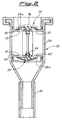
- figure 2 is an enlarged view in longitudinal cross-section of the valve for venting only, according to the invention.
- Reference is made firstly to figure 1, in order to describe briefly the part of the intake circuit in which the valve according to the present invention is installed, since this part is generally known according to the state of the art for hydro-message systems. Thus only the components of this part which are essential for understanding of the present invention are indicated and marked with reference numbers.
- 10 indicates as a whole the intake pipe of the intake circuit of the hydro-massage system, which is connected on one side to the intake orifice, not shown, which communicates with the interior of the tub (also not shown), and on the other side, to an intake pump generally indicated as 12. The
intake pump 12 is connected in any known manner, not shown, to acontrol motor 14 which drives it. - The
pump 12 is provided with a pipe indicated 16 for distribution of the water, from which there extends a branch of twopipes - The connection of the
pipes - According to one of the innovative features of the present invention, there is attached to the intake pipe 10 a valve for venting air into the atmosphere, which is generally indicated by the
reference 22. - This
valve 22 comprises avalve body 24 which is connected by means of aconnection pipe 26 to asleeve portion 28 which communicates with the interior of theintake pipe 10 and is integral with the latter. - According to one of the innovative features of the present invention, as can be seen also in figure 1, the
valve 22 for venting, and more specifically its connection to theintake pipe 10 is disposed upstream of thepump 12, according to the direction in which the latter admits the water.. - The form of the
valve 22 for venting is now described in detail, with reference also to figure 2. - Substantially in the upper part of the
valve body 24, the valve in question comprises astationary wall 30 which is provided with a series ofholes 32, disposed for example equidistantly around a circumference, which, when thevalve 22 is open, permit venting of the air to the exterior of the latter, in particular into the atmosphere with which thevalve 22 communicates at its upper end. - With the
stationary wall 30 there is associated adiaphragm closure member 34, which can assume two operative positions, the first of which, corresponding to closing of the valve, is represented by a continuous line in figure 2, whereas the second, corresponding to opening of the valve, is that shown by the broken line, relative only to the actual diaphragm indicated 34a. - The
diaphragm closure member 34, and more specifically itsdiaphragm 34a, has a substantially convex shape in the direction of thestationary wall 30, such that thisdiaphragm 34a engages with this wall only with the contour of the diaphragm, around the area where theholes 32 are provided. - The
diaphragm 34a of theclosure member 34 is provided on the side facing thewall 30 with a substantiallycentral projection 36, the specific shape of which permits displacements of theclosure member 34 along the longitudinal axis of thevalve body 24. - More specifically, this
shaped projection 36 has a base portion which extends from thediaphragm 34a, which can for example be substantially cylindrical, extending in an intermediate portion, which for example is also substantially cylindrical, and can slide freely within a central passage of thewall 30. This intermediate portion ends at the end of theprojection 36, which is enlarged for the reasons which will be better understood hereinafter in the present description. - As can be seen also in particular in figure 2, the initial, end portion of the
projection 36 of thediaphragm closure member 34 has a width greater than that of the passage inside which the intermediate portion of theprojection 36 can be displaced. By this means this initial, end portion of theprojection 36 constitutes a stop for the displacements of thediaphragm closure member 34 from its closing position to its opening position and vice versa. - It should be noted that raising of the
diaphragm 34a of thediaphragm closure member 34 does not require a particularly intensive thrust action, both because this closure member is made of a material which makes it particularly light, such as rubber, a plastics material or the like, and because sliding of the intermediate portion of theprojection 36 takes place with particularly low friction. In this respect the flow of air which rises from the base, through thepipe 26 inside thevalve body 24, is sufficient to raise theclosure member 34. This flow of air in particular has particularly low intensity, such that the pressure generated has a correspondingly low value. This is derived in particular from the fact that this rising flow of air is generated simply by the action of the water which enters theintake pipe 10, and cannot yet reach the interior of thepump 12, but is sufficient to thrust the air present in the pipes of the intake circuit towards thevalve 22. - The movement of lowering the
diaphragm 34a of theclosure member 34 to the position of closing of thevalve 22, as well as taking place very quickly, is caused by a very intensive thrust constituted in particular by the action of intake or depression created by thepump 12, which has been able to be primed, on completion of emergence of the air through thevalve 22. - The action of intake of the
pump 12 is particularly intensive because it must guarantee circulation of the water inside all of the intake circuit of the hydro- massage system. Consequently thediaphragm 34a is maintained firmly and stably against thewall 30, closing theholes 32 safety and reliably, and thus preventing any intake of air in the intake circuit, which would detract from satisfactory operation of thepump 12. The speed with which thevalve 22 is closed and the stability of the positioning of thediaphragm 34a in this condition, also prevent the slightest quantity of air from entering thevalve 22 and therefore the water intake circuit. Again with particular reference to figure 1, but consulting also figure 1, it can be seen that inside thevalve body 24, there are associated with thediaphragm closure member 34 means for preventing water from the intake circuit of thevalve body 24 from flowing back inside the latter. This situation generally occurs when thepump 12 is stopped in order to interrupt the hydro-massage. This operation leads to a generally fast return of the water into thepipe 26, which is thus quickly filled with water, whereas previously, with hydro-massage in progress, thispipe 26 had been empty. The water rises in thepipe 26 in particular in accordance with the principle of communicating vessels, since, as can be seen in particular in figure 1, thedelivery pipes pipe 26. It is clear that when the action of intake of thepump 12 is lacking, the water present in the intake circuit tends to fill thepipe 26. For safety reasons, and in the first instance to prevent the water which fills thepipe 26 from going inside thebody 24 of thevalve 22, the length of thepipe 26 is such that thevalve 22 is above the maximum filling level of the water in the tub, which is shown schematically by the line H in figure 1. It is however clear that even having taken this precautionary measure, rising of the water in thepipe 26 can be of particularly great speed and intensity, by this means making the water in thepipe 26 rise above the level H. In other words a water hammer effect could arise, which would force the water inside thebody 24 of thevalve 22 if means, which are described in detail hereinafter, were not provided to prevent this intake. - These means for stopping the flow of water from the
pipe 26 inside thebody 24 of thevalve 22 comprise a second diaphragm closure member, thediaphragm 38a of which is disposed symmetrically and specularly in relation to thediaphragm 34a of thediaphragm closure member 34. - More specifically the
diaphragms wall 30 and astationary wall 40 with which thisdiaphragm 38a cooperates. The latter is provided withholes 42 which, during operating before priming of thepump 12, permit passage of the air towards the firstdiaphragm closure member 34. - The
diaphragm 38a of the seconddiaphragm closure member 38 also has a suitably shaped substantially central projection which is substantially like that of thefirst diaphragm 34a, i.e. which has an enlarged initial end portion which can constitute a stop for translation of the membrane, and more particularly translation of its intermediate portion in a passage of thestationary wall 40. These stops correspond in particular to the positioning of thediaphragm 38a in the position shown in figure 2, corresponding to passage of the air, and a position not shown in which thisdiaphragm 38a engages with thiswall 40 in order to close the passages orboles 42, and prevent the flow of water inside thechamber 24. - This is particularly important both because a flow of water towards the first
diaphragm closure member 34 could cause encrustations on the latter, consequently giving rise to incorrect operation, and because this return flow of water would cause raising of the firstdiaphragm closure member 34 and spillage of water outside thevalve 22 and therefore on the bathroom floor. - According to a further advantageous feature of the valve according to the present invention, in order to prevent closing of the
holes 42 by the seconddiaphragm closure member 38 during passage of the air, thisclosure member 38 can simply be made slightly heavier, for example by fitting at least one washer on the initial, enlarged part of itsprojection 44, such that the flow of air which rises inside thevalve body 24 is not such as to give rise to engagement of the seconddiaphragm closure member 38 with thewall 40. - From the above description it is apparent that both bleeding of the air initially present in the intake circuit, and the feature of preventing water from flowing back in the
body 24 of thevalve 22 are provided by the latter very simply and reliably. In addition, the structural simplicity of the valve according to the present invention means that it has a low production cost, and is therefore economically convenient. - A further advantage of the valve for venting according to the present invention consists in that it reduces considerably the time necessary for priming of the intake pump, such that altogether the hydro-massage system goes into operation quickly.
- Finally it is clear that conceptually and structurally equivalent variants and / or modifications can be made to the valve for venting according to the present invention, without departing from the context of its protection.
- For example the
first closure member 34 can be stationary and itsdiaphragm 34a can be made of an easily deformable elastic material. In this case disengagement of thediaphragm 34a takes place by elastic deformation upwards, caused by the aforementioned flow of air which rises in thebody 24 of thevalve 22.
Claims (11)
- Valve for venting the air from the intake pipe of an intake circuit for the water in a hydro-massage system, characterised in that it comprises a valve body (24) which is connected on one side to this intake pipe (10) and, on the other side can be made to communicate with the atmosphere by a diaphragm closure member (34) which is associated with a wall (30) provided with holes (32) for bleeding the air, which closure member can assume a first position which corresponds to opening of the valve (22), in which it is disengaged from the wall (30) provided with holes (32) for bleeding the air, and is brought into this position by the flow of air which rises in the valve body (24) owing to the action of intake of water in the intake pipe (10), and a second position corresponding to closing of the valve (22), in which it engages with this wall (30) provided with holes (32) for bleeding the air, by the action of the depression generated by the intake pump (12) when it has been primed, and with this diaphragm closure member (34) there are associated means for preventing the water from flowing back inside a pipe (26) which connects the valve (22) to the intake pipe (10), in the event of interruption of operation of the hydro- massage system, and more particularly if operation of the intake pump (12) is stopped.
- Valve for venting according to claim 1, characterised in that this diaphragm closure member (34) is disposed above the wall (30) which is provided with holes (32) for bleeding the air, and has a shaped projection (36) which faces downwards, the central portion of which can slide freely inside a passage of this wall (30) which extends above and below in two enlarged portions which constitute the stops for movement of the diaphragm closure member (34) between these two positions which correspond to opening and closing of the valve (22).
- Valve for venting according to claim 1, characterised in that the diaphragm (34a) of this diaphragm closure member (34) has a substantially concave form on the side facing this wall (30) provided with holes (32) for bleeding the air.
- Valve for venting according to claim 1, characterised in that the length of the pipe (26) which connects the valve body (24) to the intake pipe (10) is of a value such that the upper end of this pipe (26) is substantially at the same height as the delivery pipes (18, 20) of the water intake circuit.
- Valve for venting according to claim 4, characterised in that the valve body (24) which is attached to the upper end of this pipe (26) is substantially above the maximum filling level (H) of the water in the tub to which the hydro-massage system is connected
- Valve for venting according to claim 1, characterised in that it is connected to the intake pipe (10) upstream of the intake pump (12), according to the flow of water in the intake circuit.
- Valve for venting according to claim 1, characterised in that these means for preventing water from flowing back inside the pipe (26) which connects the valve body (24) to the intake pipe (10) consist substantially of a second diaphragm closure member (38) which is also associated with a wall provided with holes (42) for passage of the air in the direction of the first diaphragm closure member (34).
- Valve for venting according to claim 7, characterised in that the diaphragm (38a) of this second diaphragm closure member (38) is disposed below the second wall (40), symmetrically relative to the diaphragm (34a) of the first diaphragm closure member (34).
- Valve for venting according to claim 7, characterised in that the second diaphragm closure member (38) can also assume two positions, in one of which it permits passage of the air through the holes (42) of the wall (40), whereas in the second it engages with the lower surface of this wall (40) in order to prevent passage of water through these holes (42).
- Valve for venting according to claims 8 and 9, characterised in that the diaphragm (38a) of this second diaphragm closure member (38) is also provided with a substantially central projection which faces upwards, and has two enlarged, end portions connected by a central portion which can slide in a passage of this wall 40, these enlarged portions constituting the stops for displacements of this diaphragm (38a) between these two positions.
- Valve for venting according to claims 1 and 3, characterised in that the first closure member (34) is stationary and its diaphragm (34a) consists of elastic, easily deformable material such that it is disengaged from the wall (30) by elastic deformation upwards caused by the flow of air which rises in the body (24) of the valve (22).
Applications Claiming Priority (2)
| Application Number | Priority Date | Filing Date | Title |
|---|---|---|---|
| ITTV960018 IT242095Y1 (en) | 1996-03-25 | 1996-03-25 | AIR RELEASE VALVE FROM THE SUCTION DUCT OF A SUCTION UNIT FOR WHIRLPOOL |
| ITTV960018U | 1996-03-25 |
Publications (2)
| Publication Number | Publication Date |
|---|---|
| EP0797973A1 true EP0797973A1 (en) | 1997-10-01 |
| EP0797973B1 EP0797973B1 (en) | 2003-12-17 |
Family
ID=11419833
Family Applications (1)
| Application Number | Title | Priority Date | Filing Date |
|---|---|---|---|
| EP19970200864 Expired - Lifetime EP0797973B1 (en) | 1996-03-25 | 1997-03-21 | Valve for venting the air from the intake pipe of an intake orificie for hydro-massage |
Country Status (4)
| Country | Link |
|---|---|
| EP (1) | EP0797973B1 (en) |
| DE (1) | DE69726782T2 (en) |
| ES (1) | ES2212035T3 (en) |
| IT (1) | IT242095Y1 (en) |
Citations (3)
| Publication number | Priority date | Publication date | Assignee | Title |
|---|---|---|---|---|
| US3580247A (en) * | 1968-09-12 | 1971-05-25 | Richard C Schneider | Hydrotherapeutic device |
| US4054152A (en) * | 1975-03-11 | 1977-10-18 | Nippondenso Co., Ltd. | Check valve |
| US4275713A (en) * | 1980-02-25 | 1981-06-30 | Linn Tellander | Hydromassage air injector apparatus |
-
1996
- 1996-03-25 IT ITTV960018 patent/IT242095Y1/en active
-
1997
- 1997-03-21 EP EP19970200864 patent/EP0797973B1/en not_active Expired - Lifetime
- 1997-03-21 ES ES97200864T patent/ES2212035T3/en not_active Expired - Lifetime
- 1997-03-21 DE DE1997626782 patent/DE69726782T2/en not_active Expired - Lifetime
Patent Citations (3)
| Publication number | Priority date | Publication date | Assignee | Title |
|---|---|---|---|---|
| US3580247A (en) * | 1968-09-12 | 1971-05-25 | Richard C Schneider | Hydrotherapeutic device |
| US4054152A (en) * | 1975-03-11 | 1977-10-18 | Nippondenso Co., Ltd. | Check valve |
| US4275713A (en) * | 1980-02-25 | 1981-06-30 | Linn Tellander | Hydromassage air injector apparatus |
Also Published As
| Publication number | Publication date |
|---|---|
| ES2212035T3 (en) | 2004-07-16 |
| DE69726782T2 (en) | 2004-11-11 |
| ITTV960018U1 (en) | 1997-09-25 |
| ITTV960018V0 (en) | 1996-03-25 |
| DE69726782D1 (en) | 2004-01-29 |
| EP0797973B1 (en) | 2003-12-17 |
| IT242095Y1 (en) | 2001-06-04 |
Similar Documents
| Publication | Publication Date | Title |
|---|---|---|
| US4034423A (en) | Valve controlled flushing system | |
| EP0596977B1 (en) | Diaphragm pump | |
| US4444230A (en) | Tank-mounted filling device | |
| US3729017A (en) | Flow-control device | |
| US3516094A (en) | Toilet flushing apparatus | |
| JPS5918497B2 (en) | Control device for siphon type cleaning valve | |
| US3459207A (en) | Faucet construction | |
| EP0797973A1 (en) | Valve for venting the air from the intake pipe of an intake orificie for hydro-massage | |
| KR840006519A (en) | Float valve | |
| US6098648A (en) | Intake for whirlpool-type bathtub | |
| US4399835A (en) | Water saving toilet control valve | |
| US1044311A (en) | Float-operated valve. | |
| US3575210A (en) | Automatic refill device having fluidically operated control | |
| US2792011A (en) | Flood control means | |
| FR2506888B1 (en) | ||
| US4587679A (en) | Toilet flushing device | |
| US3695284A (en) | Valve structure for controlling flow of liquid into a pneumatic liquid disposal system | |
| US2914293A (en) | Pilot controlled flush valves | |
| CA1053406A (en) | Valve controlled flushing system | |
| US924345A (en) | Ball-cock. | |
| US3421539A (en) | Commode valve assembly | |
| US6962163B1 (en) | Dual-float snap-action flush valve | |
| US3714954A (en) | Fluidic flushing mechanism | |
| US3680573A (en) | Pilot valve operated fluidic valve | |
| EP0730857B1 (en) | Suction nozzle for hydromassage |
Legal Events
| Date | Code | Title | Description |
|---|---|---|---|
| PUAI | Public reference made under article 153(3) epc to a published international application that has entered the european phase |
Free format text: ORIGINAL CODE: 0009012 |
|
| AK | Designated contracting states |
Kind code of ref document: A1 Designated state(s): DE ES FR GB IT |
|
| 17P | Request for examination filed |
Effective date: 19980312 |
|
| 17Q | First examination report despatched |
Effective date: 20000921 |
|
| GRAH | Despatch of communication of intention to grant a patent |
Free format text: ORIGINAL CODE: EPIDOS IGRA |
|
| GRAS | Grant fee paid |
Free format text: ORIGINAL CODE: EPIDOSNIGR3 |
|
| GRAA | (expected) grant |
Free format text: ORIGINAL CODE: 0009210 |
|
| AK | Designated contracting states |
Kind code of ref document: B1 Designated state(s): DE ES FR GB IT |
|
| REG | Reference to a national code |
Ref country code: GB Ref legal event code: FG4D |
|
| REF | Corresponds to: |
Ref document number: 69726782 Country of ref document: DE Date of ref document: 20040129 Kind code of ref document: P |
|
| PG25 | Lapsed in a contracting state [announced via postgrant information from national office to epo] |
Ref country code: GB Free format text: LAPSE BECAUSE OF NON-PAYMENT OF DUE FEES Effective date: 20040321 |
|
| REG | Reference to a national code |
Ref country code: ES Ref legal event code: FG2A Ref document number: 2212035 Country of ref document: ES Kind code of ref document: T3 |
|
| ET | Fr: translation filed | ||
| PLBE | No opposition filed within time limit |
Free format text: ORIGINAL CODE: 0009261 |
|
| STAA | Information on the status of an ep patent application or granted ep patent |
Free format text: STATUS: NO OPPOSITION FILED WITHIN TIME LIMIT |
|
| GBPC | Gb: european patent ceased through non-payment of renewal fee |
Effective date: 20040321 |
|
| 26N | No opposition filed |
Effective date: 20040920 |
|
| PGFP | Annual fee paid to national office [announced via postgrant information from national office to epo] |
Ref country code: ES Payment date: 20100326 Year of fee payment: 14 |
|
| PGFP | Annual fee paid to national office [announced via postgrant information from national office to epo] |
Ref country code: FR Payment date: 20100406 Year of fee payment: 14 |
|
| PGFP | Annual fee paid to national office [announced via postgrant information from national office to epo] |
Ref country code: IT Payment date: 20100329 Year of fee payment: 14 Ref country code: DE Payment date: 20100329 Year of fee payment: 14 |
|
| REG | Reference to a national code |
Ref country code: FR Ref legal event code: ST Effective date: 20111130 |
|
| PG25 | Lapsed in a contracting state [announced via postgrant information from national office to epo] |
Ref country code: FR Free format text: LAPSE BECAUSE OF NON-PAYMENT OF DUE FEES Effective date: 20110331 Ref country code: DE Free format text: LAPSE BECAUSE OF NON-PAYMENT OF DUE FEES Effective date: 20111001 |
|
| REG | Reference to a national code |
Ref country code: DE Ref legal event code: R119 Ref document number: 69726782 Country of ref document: DE Effective date: 20111001 |
|
| PG25 | Lapsed in a contracting state [announced via postgrant information from national office to epo] |
Ref country code: IT Free format text: LAPSE BECAUSE OF NON-PAYMENT OF DUE FEES Effective date: 20110321 |
|
| REG | Reference to a national code |
Ref country code: ES Ref legal event code: FD2A Effective date: 20120424 |
|
| PG25 | Lapsed in a contracting state [announced via postgrant information from national office to epo] |
Ref country code: ES Free format text: LAPSE BECAUSE OF NON-PAYMENT OF DUE FEES Effective date: 20110322 |