EP0797779B1 - Device for speed measurement in a rail-mounted vehicle - Google Patents
Device for speed measurement in a rail-mounted vehicle Download PDFInfo
- Publication number
- EP0797779B1 EP0797779B1 EP95925206A EP95925206A EP0797779B1 EP 0797779 B1 EP0797779 B1 EP 0797779B1 EP 95925206 A EP95925206 A EP 95925206A EP 95925206 A EP95925206 A EP 95925206A EP 0797779 B1 EP0797779 B1 EP 0797779B1
- Authority
- EP
- European Patent Office
- Prior art keywords
- sensor
- vehicle
- signal
- rail
- coil
- Prior art date
- Legal status (The legal status is an assumption and is not a legal conclusion. Google has not performed a legal analysis and makes no representation as to the accuracy of the status listed.)
- Expired - Lifetime
Links
- 238000005259 measurement Methods 0.000 title claims description 26
- 238000006073 displacement reaction Methods 0.000 claims abstract description 7
- 230000005415 magnetization Effects 0.000 claims description 48
- 238000001514 detection method Methods 0.000 claims description 16
- 230000007547 defect Effects 0.000 claims description 8
- 102100036601 Aggrecan core protein Human genes 0.000 claims description 5
- 108091006419 SLC25A12 Proteins 0.000 claims description 5
- 239000008186 active pharmaceutical agent Substances 0.000 claims 3
- 238000012545 processing Methods 0.000 description 15
- 238000012360 testing method Methods 0.000 description 6
- 230000035945 sensitivity Effects 0.000 description 5
- 230000002596 correlated effect Effects 0.000 description 4
- 230000006870 function Effects 0.000 description 4
- 238000004804 winding Methods 0.000 description 4
- 101100350613 Arabidopsis thaliana PLL1 gene Proteins 0.000 description 3
- 230000000875 corresponding effect Effects 0.000 description 3
- 230000010354 integration Effects 0.000 description 3
- 238000000034 method Methods 0.000 description 3
- 238000012544 monitoring process Methods 0.000 description 3
- 230000003287 optical effect Effects 0.000 description 3
- 101001122448 Rattus norvegicus Nociceptin receptor Proteins 0.000 description 2
- 229910052782 aluminium Inorganic materials 0.000 description 2
- 230000003321 amplification Effects 0.000 description 2
- 238000004364 calculation method Methods 0.000 description 2
- 238000010586 diagram Methods 0.000 description 2
- 230000005672 electromagnetic field Effects 0.000 description 2
- 238000003199 nucleic acid amplification method Methods 0.000 description 2
- 230000035515 penetration Effects 0.000 description 2
- 230000005855 radiation Effects 0.000 description 2
- 239000013598 vector Substances 0.000 description 2
- 238000007476 Maximum Likelihood Methods 0.000 description 1
- 101100464779 Saccharomyces cerevisiae (strain ATCC 204508 / S288c) CNA1 gene Proteins 0.000 description 1
- 230000001133 acceleration Effects 0.000 description 1
- 230000003044 adaptive effect Effects 0.000 description 1
- XAGFODPZIPBFFR-UHFFFAOYSA-N aluminium Chemical compound [Al] XAGFODPZIPBFFR-UHFFFAOYSA-N 0.000 description 1
- 239000004411 aluminium Substances 0.000 description 1
- 238000004458 analytical method Methods 0.000 description 1
- 238000013459 approach Methods 0.000 description 1
- 238000000576 coating method Methods 0.000 description 1
- 239000004020 conductor Substances 0.000 description 1
- 238000010219 correlation analysis Methods 0.000 description 1
- 238000013016 damping Methods 0.000 description 1
- 230000001419 dependent effect Effects 0.000 description 1
- 239000000428 dust Substances 0.000 description 1
- 230000002500 effect on skin Effects 0.000 description 1
- 230000008030 elimination Effects 0.000 description 1
- 238000003379 elimination reaction Methods 0.000 description 1
- 238000001914 filtration Methods 0.000 description 1
- 230000006698 induction Effects 0.000 description 1
- 238000009434 installation Methods 0.000 description 1
- 238000005457 optimization Methods 0.000 description 1
- 239000002245 particle Substances 0.000 description 1
- 238000003909 pattern recognition Methods 0.000 description 1
- 230000035699 permeability Effects 0.000 description 1
- 230000010363 phase shift Effects 0.000 description 1
- 238000012216 screening Methods 0.000 description 1
- 230000011664 signaling Effects 0.000 description 1
- 230000003068 static effect Effects 0.000 description 1
Images





Classifications
-
- G—PHYSICS
- G01—MEASURING; TESTING
- G01P—MEASURING LINEAR OR ANGULAR SPEED, ACCELERATION, DECELERATION, OR SHOCK; INDICATING PRESENCE, ABSENCE, OR DIRECTION, OF MOVEMENT
- G01P3/00—Measuring linear or angular speed; Measuring differences of linear or angular speeds
- G01P3/64—Devices characterised by the determination of the time taken to traverse a fixed distance
- G01P3/80—Devices characterised by the determination of the time taken to traverse a fixed distance using auto-correlation or cross-correlation detection means
- G01P3/803—Devices characterised by the determination of the time taken to traverse a fixed distance using auto-correlation or cross-correlation detection means in devices of the type to be classified in G01P3/66
-
- B—PERFORMING OPERATIONS; TRANSPORTING
- B60—VEHICLES IN GENERAL
- B60L—PROPULSION OF ELECTRICALLY-PROPELLED VEHICLES; SUPPLYING ELECTRIC POWER FOR AUXILIARY EQUIPMENT OF ELECTRICALLY-PROPELLED VEHICLES; ELECTRODYNAMIC BRAKE SYSTEMS FOR VEHICLES IN GENERAL; MAGNETIC SUSPENSION OR LEVITATION FOR VEHICLES; MONITORING OPERATING VARIABLES OF ELECTRICALLY-PROPELLED VEHICLES; ELECTRIC SAFETY DEVICES FOR ELECTRICALLY-PROPELLED VEHICLES
- B60L3/00—Electric devices on electrically-propelled vehicles for safety purposes; Monitoring operating variables, e.g. speed, deceleration or energy consumption
- B60L3/10—Indicating wheel slip ; Correction of wheel slip
-
- B—PERFORMING OPERATIONS; TRANSPORTING
- B60—VEHICLES IN GENERAL
- B60L—PROPULSION OF ELECTRICALLY-PROPELLED VEHICLES; SUPPLYING ELECTRIC POWER FOR AUXILIARY EQUIPMENT OF ELECTRICALLY-PROPELLED VEHICLES; ELECTRODYNAMIC BRAKE SYSTEMS FOR VEHICLES IN GENERAL; MAGNETIC SUSPENSION OR LEVITATION FOR VEHICLES; MONITORING OPERATING VARIABLES OF ELECTRICALLY-PROPELLED VEHICLES; ELECTRIC SAFETY DEVICES FOR ELECTRICALLY-PROPELLED VEHICLES
- B60L2200/00—Type of vehicles
- B60L2200/26—Rail vehicles
Definitions
- US patent specification 4 179 744 describes a device for checking the function of electric rail-mounted vehicles.
- the device has one or more stationary sensors placed along the rail, which are connected to stationary measurement amplifiers and signal processing equipment. When the vehicle passes the sensors, these detect the electromagnetic fields from the traction equipment of the vehicle. This makes possible control and analysis of the function of the traction equipment. By arranging two such sensors at a known distance from each other along the rail, and by allowing the signal processing equipment to determine the time displacement between the signals from the two sensors, the speed of the vehicle may be calculated.
- the device requires stationary installations and it may only give information about the vehicle speed at that moment when the vehicle passes the sensors and cannot give the continuous speed information which is required for, for example, position determination or slip control.
- a continuous calculation of the correlation between the signals S1 and S2 is made when these are displaced by a varying time interval ⁇ relative to each other.
- the time displacement ⁇ m which provides the highest value of the correlation integral is used as one subset for the speed determination.
- the result of previous measurements (the previous history), modelling of the dynamic properties of the vehicle (the train), possibly other (less accurate) speed sensors, as, for example, a tachometer generator, are used as input data.
- the evaluation program which is a statistical probability calculation with adaptive weights of the various input data, then provides an MLE (Maximum Likelihood Estimation) of the instantaneous speed of the vehicle.
- a separate monitoring winding may be adapted to sense the amplitude and/or phase of the magnetization field.
- a monitoring unit is adapted to trigger an alarm in the event of loss of the magnetization field, or if the characteristics of the field deviate from the desired ones.
Landscapes
- Engineering & Computer Science (AREA)
- Mechanical Engineering (AREA)
- Physics & Mathematics (AREA)
- General Physics & Mathematics (AREA)
- Sustainable Development (AREA)
- Sustainable Energy (AREA)
- Power Engineering (AREA)
- Life Sciences & Earth Sciences (AREA)
- Transportation (AREA)
- Train Traffic Observation, Control, And Security (AREA)
- Measurement Of Length, Angles, Or The Like Using Electric Or Magnetic Means (AREA)
- Measuring Magnetic Variables (AREA)
- Investigating Or Analyzing Materials By The Use Of Magnetic Means (AREA)
- Indicating Or Recording The Presence, Absence, Or Direction Of Movement (AREA)
- Length Measuring Devices With Unspecified Measuring Means (AREA)
- Investigating Or Analyzing Materials By The Use Of Ultrasonic Waves (AREA)
Abstract
Description
- The present invention relates to a device for speed measurement in a rail-mounted vehicle.
- It has long been desired to be able to measure the speed of a rail-mounted vehicle accurately and with a high reliability over the whole speed range of the vehicle and under all operating conditions. An accurate speed value is desirable to be able to obtain, by integration, the distance covered by the vehicle and hence the position of the vehicle along the track, which information is required by superordinate traffic control systems. Further, it is desirable to obtain an accurate speed value for information to systems for control of the vehicle slip during acceleration or deceleration, and it is then important to obtain a good speed measure also at a very low speed.
- Further, inter alia for reasons of reliability and cost, it is desirable that means for speed measurement and position determination be arranged in their entirety on the vehicle and that they be completely, or to the greatest possible degree, independent of external means, such as stationary signalling or measurement systems arranged at the track or at some other location.
- It is previously known to use tachometer generators connected to the wheels of the vehicle. However, slipping of the wheels when driving or braking entails unavoidable measurement errors in such equipment. Further, the measures of speed and distance, which are obtained from a tachometer generator, are dependent on the current wheel diameter. This is changed with time, both by wear and by the wheels being turned down, which is done at regular intervals. The influence of the diameter change may to a certain extent be compensated by recurring calibrations and adjustments of the measurement system, but the need thereof entails an essential drawback, and under all circumstances a tachometer generator system can probably not provide a higher accuracy in, for example, the distance measurement than some 10 to 30 percent.
- In, inter alia, the article entitled "Hastighetsmätning med korrelationsmetod", Andermo, Mörk, Sjölund, Teknisk Tidskrift 1976, No. 3, pages 18-21, it has been proposed (Figure 3 with description) that the speed of a rail-mounted vehicle may be measured optically in a contactless manner with the aid of a correlation method. A sensor mounted in a bogie has two light-emitting diodes which illuminate the rail at two different locations at a known distance from each other. The reflected radiation is sensed at both locations with the aid of photodiodes. One of the sensed signals is displaced in time until a maximum correlation is obtained between the two time-variable signals. The time displacement together with the known distance between the measuring locations then provides the speed of the vehicle and, by integration, the distance covered. However, in practice, it has been found that optical systems are sensitive to the heavy fouling of detectors, etc., which is unavoidable during vehicle operation. Further, particles present between the rail and the sensor, such as, for example, raindrops, snow, and brake dust, result in disturbances of the measurement, among other things by heavy damping of the optical signals. Therefore, it has proved to be difficult, or impossible, to obtain a high reliability and a high measurement accuracy during operation in vehicle environment using equipment of the above-mentioned type.
- In Jopping, Wennrich: "Radargestützte Weg- und Geschwindigkeitsmessung auf Schienenfahrzeugen, Signal+Draht, 85 (1993), pages 360-364, a system for speed and road measurement during vehicle operation with the aid of a doppler radar is described. Such a system has proved to be less sensitive to fouling than an optical system. During vehicle operation in the winter in a Nordic or arctic climate, however, it has proved that the unavoidable presence of snow and ice coatings obstructs the radar radiation to such a high extent that the system cannot be used under these conditions. Further, in measurement equipment of this kind, it has proved to be difficult to obtain the required accuracy of measurement at a low vehicle speed.
- US patent specification 4 179 744 describes a device for checking the function of electric rail-mounted vehicles. The device has one or more stationary sensors placed along the rail, which are connected to stationary measurement amplifiers and signal processing equipment. When the vehicle passes the sensors, these detect the electromagnetic fields from the traction equipment of the vehicle. This makes possible control and analysis of the function of the traction equipment. By arranging two such sensors at a known distance from each other along the rail, and by allowing the signal processing equipment to determine the time displacement between the signals from the two sensors, the speed of the vehicle may be calculated. The device requires stationary installations and it may only give information about the vehicle speed at that moment when the vehicle passes the sensors and cannot give the continuous speed information which is required for, for example, position determination or slip control.
- US patent specification 4 283 031 describes a device for use in connection with railway crossings. It has stationary sensors arranged along the rail for determining, for example, the length of the train, the number of cars, the train speed and direction. Each sensor is arranged near the rail and senses those changes in an electromagnetic field, generated by the sensor, which are caused by wheel passages. By determining the time between the passages by a vehicle wheel past two sensors arranged at a known distance from each other, the train speed may be determined. The device involves the same disadvantages as the device described in the preceding paragraph.
- US patent specification 5 141 183 describes a device in a handling system (e.g. an overhead travelling crane or an industrial robot arranged on a trolley) comprising a carriage movable along a rail. The carriage has current collectors running along stationary contact rails. On the rails, magnetized strips are arranged which have regions with alternately opposite magnetization directions. The current collector is provided with a sensor which senses the field from the strip and which counts the regions which are passed. If the regions have known dimensions, the speed of the car may be determined. Also this device requires stationary members (the magnetic strips) and may, therefore, only give speed information upon the very passage of the stationary members.
- The invention aims to provide a device of the kind described in the introductory part of the description, which within the whole speed range of the vehicle exhibits a high reliability and a high accuracy of measurement also under very severe operating conditions, and which is able to work completely independently of means or systems arranged outside the vehicle.
- Further, the invention aims to provide a device which makes possible a reliable detection of non-movement of the vehicle.
- The invention also aims to provide a device which makes possible detection of rail defects, such as cracks and rail failures.
- What characterizes a measurement system according to the invention will become clear from the appended claims.
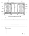
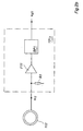
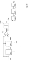
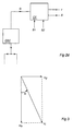
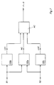
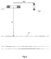
- The invention will be described in greater detail in the following with reference to the accompanying Figures 1-9. Figure 1 shows a sensor means according to the invention, wherein Figure 1a shows the means viewed from the side, Figure 1b the means viewed from above, Figure 1c the means viewed in the direction of movement of the vehicle, Figure 1d a sensor means in an alternative embodiment, viewed from above, and Figure le an example of the mounting of the sensor means on the vehicle. Figure 2a shows a block diagram of a measurement device according to the invention. Figure 2b shows the configuration of the electronic system, arranged in the sensor itself, in the means according to Figure 2a. Figure 2c shows the configuration of the circuits for signal processing of each one of the two sensor signals in the means according to Figure 2a. Figure 2d shows how the device according to Figure 2a may be supplemented in order to work alternately at two different frequencies. Figure 3 shows in the form of a vector diagram the components of the output signal of the sensor coil. Figure 4 shows an alternative embodiment of the sensor means according to the invention, with sensor coils in two directions orthogonal to each other. Figure 5 shows a sensor means with three sensor units and with a possibility of choosing between two different measurement distances. Figure 6 shows how the switching between the measurement distances may be made in the device according to Figure 5. Figure 7 shows an example of how the device according to the invention may be supplemented for detection of non-movement of the vehicle. Figure 8 shows an example of how the device according to the invention may be supplemented with means for detection of defects in the rail. Figure 9 shows an alternative embodiment of the magnetization and sensor coils of the sensor means.
- The examples of electric and mechanical dimensioning information occurring in the following description are only approximate.
- Figure la shows a sensor means according to the invention. It is arranged on a vehicle bogie above a
rail 2, the longitudinal direction of which coincides with the direction of movement of the vehicle and lies in the plane of the paper. The sensor means comprises ahousing 1 made of electrically conducting material, for example aluminium. The electrically conducting house walls provide screening between the sensors and against disturbances from external fields. The housing has threespaces spaces 11 and 12 a sensor, G1 and G2, respectively, is arranged. Each sensor has acoil frame magnetization coil - The distance d between the lower part of the sensor means and the upper surface of the
rail 2 is, for example, 50-100 mm. It is adapted with respect to the deflection of the bogie and to the reduction of the diameter of the vehicle wheels which arises when the wheels are turned down which is normally done at certain intervals. - The distance L in the direction of movement between the axes of the two sensors is about 100 mm in the example shown. Each sensor system (with at least two sensors) is measured individually to obtain an equivalent "electrical distance", L'EL, which is then stored in a non-volatile memory (e.g. an E2 memory). This distance, L'EL, is then utilized as calibration value by the signal processing unit.
- In the
common space 13 between the two sensors, certain electronic equipment is arranged on a printed circuit-board 131. In the example described, this electronic equipment consists of pre-amplifiers for the signals from the sensor coils and of bandpass filters for the sensor signals. - The
housing 1 is provided with connection devices (not shown) for supply voltages to the magnetization coils and for the output signals from the printed circuit-board 131 and with the necessary connections between the sensor coils and the printed circuit-board. - Further, Figure la shows the coordinate system used hereinafter in the description. The X axis of the system is vertical and parallel to the longitudinal axes of the magnetization coils. The Y axis is parallel to the longitudinal direction of the rail, and hence to the direction of movement of the vehicle. The Z axis is horizontal and perpendicular to the longitudinal direction of the rail.
- Figure 1b shows a section through the sensor means viewed from above. Figure 1c shows a section through the sensor means viewed from the front.
- The magnetization coil of a sensor generates a magnetic alternating field - the magnetization field - with a substantially vertical main direction. Since the coil lies relatively close to the rail, the rail will influence the field. Factors which influence the field are the magnitude of the air gap between the sensor and the rail, the geometry of the rail (e.g. dimensional changes, damage, interruptions), and the permeability and conductivity of the rail. During movement of the vehicle, variations in these factors will generate correlatable variations of the magnetic field configuration. However, the variations in the field are small compared with the magnitude of the magnetization field. Since the sensor coil of each sensor is separate, however, it may be oriented in space so as to select and sense that magnetic component which best represents the changes in the field which are caused by these variations in the properties of the rail. By orienting the sensor coils in the manner shown in Figure 1, that is, orthogonally to the magnetization field, the sensitivity of the coils to the strong magnetization field is reduced to a very great extent. The field which is orthogonal to the magnetization field will in this way constitute a greatly increased percentage of the output signal from a sensor coil, and in this way it has been possible to increase the sensitivity and the accuracy of the detection of the magnetic-field variations to a very great extent.
- Figure 1d shows, viewed from above, an alternative embodiment of the
housing 1 of the sensor means. The housing consists of an extruded alumium profile with two circular parts, which form thespaces space 13 for the common electronic unit (the printed circuit-board 131). - Figure 1e shows an example of the mounting on the vehicle of the sensor means 1 shown in Figures 1a - 1c. The means is mounted on the underside of one of the bogies of the vehicle, namely, the
bogie 3 with its twowheel sets - Figure 2a shows the sensor means according to Figure 1 with associated equipment for feeding the field coils and for signal processing of the output signals of the sensor coils. A supply unit SU feeds the magnetization coils 111 and 121 with an alternating voltage with the frequency 100 kHz with the aid of a sine-wave oscillator OSC and a power amplifier PA. The output voltages ui1 and ui2 from the sensor coils 112 and 122 are supplied to the
electronic circuits board 131. The output signals ud1 and ud2 from these circuits are supplied to signal processing circuits SB1 and SB2, which generate the digital signals S1 and S2. Each such signal constitutes a measure of the instantaneous value of the phase position of the field sensed by the respective sensor coil. The signals S1 and S2 are supplied to a calculating unit CE, which by means of, inter alia, correlation of the two signals, calculates measured values of the speed v of the vehicle and the distance s covered. - Figure 2b shows the configuration of the
electronic circuit 1311. Thesensor coil 112 is connected to a load resistance R1 of 50 kohms. The voltage ui1 is supplied to an amplifier and impedance converter F11 with an amplification of 5-10 times and an output impedance of 50 ohms. The output signal of the amplifier is filtered in a bandpass filter BP1 for filtering away other signals than those which are derived from the magnetization field, which has the frequency 100 kHz. In the example now described, the filter has a passband with upper and lower limit frequencies 150 kHz and 50 kHz, respectively. The output signal from the bandpass filter is designated ud1. - The electronic 1312 is built up in the same way as the
circuit 1311. - Figure 2c shows the configuration of the signal-processing circuit SB1 shown in Figure 2a. The signal ud1 is supplied to a phase-locked loop PLL1 with a large time constant, one or a few seconds. This circuit will have a phase position which corresponds to the mean value of the phase position of the input signal ud1. The circuit generates two output signals with the same frequency as the input signal, that is, 100 kHz. An output signal ur21 has the same phase position as the input signal and is supplied to a circuit AGC1 for control of the working point of the sensor means. A second output signal consists of a square-pulse train ur11 which is phase-shifted 90° from the former output signal and is supplied to an input of an exclusive OR circuit XOR1. The signal ur11 serves as a phase-position reference when determining the phase position of the voltage generated in the sensor coil.
- The circuit AGC1 is a circuit with a controllable gain. The output signal udm1 of the circuit has the same phase position and curve shape as the input signal ur21 but a variable amplitude. The input of the circuit for control of the amplification is supplied with the signal ud1. The peak value of this signal is detected, for example in an envelope detector, and controls the amplitude of the output signal of the circuit in such a way that the amplitude of the output signal almost - but not quite - corresponds to the amplitude of the measured signal ud1. The circuit AGC1 has a large time constant, for example one or a few seconds, and the output signal udm1 will therefore have the same frequency as the measured signal ud1 and an amplitude and a phase position which nearly correspond to the mean values of the amplitude and the phase position of the measured signal ud1.
- In a differential amplifier F21 the signal Udm1 is subtracted from the measured signal ud1 and the difference constitutes the output signal u'd1 of the amplifier. The circuit PLL1 - AGCl - F21 now described will control the working point of the means such that the component in the output signal of the sensor coil which is caused by the magnetization field is eliminated to the desired extent. In this way, the sensitivity and the accuracy in the detection of the field variations caused by the vehicle movement are increased, which variations are small compared with the magnetization field.
- It has proved to be suitable not completely to eliminate the voltage component caused by the magnetization field, but to allow the output signal of the sensor coil to contain, for example, 100 mV of this component as phase reference. The XOR gate requires an input signal u'dd1 (Figure 2c), which on average should be 90° phase-shifted relative to ur11 which is obtained from the circuit PLL1. The latter circuit has found its phase position substantially from the component of the magnetization field. Therefore, a sufficiently large component from the magnetization field should also be present in the signal u'dd1 and thus also in u'd1.
- The output signal u'd1 of the amplifier F21 is supplied to a comparator CMP1 which emits a logic one if the input signal is larger than zero and a logic zero in the opposite case. The output signal u'dd1 of the comparator, which signal is a square pulse train with the same phase position and frequency as the input signal u'd1, is supplied to a second input of the XOR circuit XOR1.
- If the two input signals to the XOR circuit are in phase, the output signal of the circuit becomes zero. If the input signals are in anti-phase, the output signal becomes 1. On average, the input signal u'dd1 will have the same phase position as the measured signal ud1, that is, the phase difference between the two input signals to the XOR circuit will, on average, be 90°. On average, therefore, the output signal of the circuit will have the
value 1/2, that is, the working point will, on average, lie in the centre of the dynamic range of the circuit, which entails an optimum utilization of the dynamic range. - The output signal ϕp of the XOR circuit consists of a pulse train with the frequency 100 kHz and with a mean value which, on average, has the
value 1/2 and which may vary between the above-mentionedlimits - The signal-processing circuit SB2 in Figure 2a is built up in the same way as the circuit SB1 described above.
- The signals S1 and S2 from the signal-processing circuits SB1 and SB2 in Figure 2a are supplied to a correlation unit CE. This suitably consists of a microprocessor programmed to perform speed determination with the aid of, inter alia, correlation of the two signals S1 and S2 and to calculate, by integration/summation of the speed values, the distance covered by the vehicle.
- Each one of the signals S1 and S2 is stored continuously as a sequence of a predetermined number of digital values, which thus always reproduce the variation of the signal during a certain time prior to the moment in question.
- A continuous calculation of the correlation between the signals S1 and S2 is made when these are displaced by a varying time interval τ relative to each other. The time displacement τm which provides the highest value of the correlation integral is used as one subset for the speed determination. Further, the result of previous measurements (the previous history), modelling of the dynamic properties of the vehicle (the train), possibly other (less accurate) speed sensors, as, for example, a tachometer generator, are used as input data. The evaluation program, which is a statistical probability calculation with adaptive weights of the various input data, then provides an MLE (Maximum Likelihood Estimation) of the instantaneous speed of the vehicle. The speed of the vehicle is obtained as
- L'EL
- is the equivalent "electrical distance" between the two sensors (see Figure 1 with associated description)
- τMLE
- is the value of t which gives the best possible correlation according to MLE.
- Further, the device may be simply adapted to determine the direction of movement of the vehicle by shifting between S1 and S2 during the correlation and investigating in which order between the two signal patterns the correlation is obtained.
- The microprocessor is adapted to carry out correlation analysis with a predetermined frequency, for example 10 measurements per second.
- Figure 2d shows how increased reliability in the speed determination may be obtained by allowing the sensor means alternately to operate at two different frequencies, for example 70 kHz and 100 kHz. A control signal fc from the calculating member CE switches with a suitable periodicity, for example between each measurement, the oscillator frequency between these two values. Where necessary, filter circuits etc. in the signal-processing units SB1 and SB2 are also switched synchronously therewith. Since the depth of penetration of the field into the rail is different for the two frequencies, the sensed signal patterns will vary in different ways during the movement of the vehicle. However, the speed values calculated at one frequency shall, in principle, correspond to the values which are determined at the other frequency. If the values do not correspond, it is possible (if the difference is small) to form the mean value thereof, or (if the difference is great) to take this as an indication of a fault in the sensor means.
- As an alternative to allowing the sensor means to alternately operate at different frequencies, two or more sensor systems and measurement channels, operating at different frequencies, may be arranged.
- If desired, of course, two or more identical sensor means may be used on a vehicle to obtain a higher availability and increased reliability.
- Figure 3 shows in the form of alternating-voltage vectors the output voltage ui of a sensor coil, which voltage is composed of the two components uix and uiy. That component in the output signal of a sensor coil which is directly caused by the magnetization field may, in practice, never be eliminated by adjusting the orientation of the coil. However, by the circuit for control of the working point of the means, described above with reference to Figure 2c, as mentioned, this component may be further reduced to the desired degree. However, it has proved to be suitable not to eliminate the component completely, and therefore, in the output signal of the sensor coil, there is a component uix which is caused by the magnetization field. The field variations in the direction of sensing of the sensor coil (orthogonally to the magnetization field), which are caused by the movement of the vehicle, will substantially provide a component uiy of the output signal of the sensor, which component has a 90° phase shift relative to the component uix. The variations of the component uiy cause variations of the phase position ϕ of the output signal of the coil relative to the phase position of the component uix generated by the magnetization field. As mentioned, the orientation of the sensor coils orthogonally to the magnetization field entails a great reduction of the influence of the magnetization field on the output signal of a coil. The variations in the phase position of the sensor signal which are caused by the variations in the voltage component uiy therefore become greatly increased, which entails a good sensitivity and accuracy in the detection.
- Figure 4 shows, viewed from above, a sensor means of the same type as that shown in Figure 1. A sensor, G1 and G2, respectively, is arranged in each of the
spaces sensor coil - From the
sensor coils electronic circuits 131 arranged in the sensor, which sensor signals are signal-processed and correlated with each other for forming a measure of the speed v of the vehicle in the manner described with reference to Figure 2. The signals ud1z and ud2z are processed in the same way, either by separate signal-processing circuits and calculating means, or by using the same circuits alternately for determining the vehicle speed from the signals from one of the pairs of coils and alternately from the signals from the other pair of coils. Possibly, one of the pairs of coils with its signal-processing circuits and calculating means may be used in the normal case and the other pair of coils with its signal-processing circuits and calculating means serve as a pair of stand-by coils to be activated in the event of a fault in the normally used system. - It has been found that sensor coils with their sensing direction in the y-direction are insensitive to fields which are caused by traction and signal currents flowing in the rail, and that this coil orientation may be preferable. This is not the case with coils which have their sensing direction in the z-direction, but the disturbing influence of the above-mentioned currents may to a great extent be reduced with the aid of some disturbance elimination method known per se, for example according to the Swedish patent with publication number 441 720.
- Figure 5 schematically shows a sensor unit according to an alternative embodiment of the invention. It has three sensors, each one designed as, for example, the sensors in Figure 1. It has a sensor G1 and a sensor G2 in the same way as the sensor means of Figure 1. The distance between the centre lines of the sensors constitutes the measuring distance L. The sensor signals from the sensors G1 and G2 are correlated with each other in the manner described with reference to Figure 2, and the speed of the vehicle is calculated by means of the measuring distance L.
- Between the sensor G1 and the common
electronic space 13, a third sensor G2' of the same kind is arranged adjacent the sensor G1 and forms together therewith a shorter measuring distance L' with a length of, for example, 40 mm. At low vehicle speed, this shorter measuring distance provides considerably faster speed determination than the longer measuring distance L. As shown in Figure 6, the choice of measuring distance may preferably be made automatically in dependence on the vehicle speed. The signals ud2 and u'd2 from the sensors G2 and G2', respectively, are supplied to the signal-processing unit SB2 via electronic switching members SW1 and SW2. A level-sensing circuit NV1 is supplied with the calculated speed value v. If the speed is greater than a certain predetermined value v0, the longer measuring distance is used and the signal ud2 is switched via the switching member SW1 into the signal-processing unit SB2. If the speed does not exceed the value v0, the shorter measuring distance is activated by instead switching the signal u'd2 via the switching member SW2 into the unit SB2. - Although the system described above with a suitable dimensioning may provide a good measurement result down to a very low speed, the measurement system unavoidably ceases to function when the speed approaches zero. In many applications, therefore, it is desirable to complete the system with an indication as to whether the speed of the vehicle is zero.
- When the vehicle is stationary, S1 and S2 will be uncorrelated time sequences for all time displacements τ between the sequences. One method is to test for total independence when the estimated value of the speed is below a predetermined limit. When this hypothesis is verified at a given significance level, uncorrelated sequences are indicated. In addition, S1 and S2 will be approximately static sequences when the speed is zero. A low variance (RMS value) is, therefore, also an indication of the speed being zero.
- Figure 7 shows how these tests may be combined. The calculating unit CEa is supplied with the signals S1 and S2 and delivers - if the above-mentioned test of the absence of correlation is fulfilled - a signal NC which indicates that the two signals are uncorrelated. The circuits CEb and CEc deliver signals LV1 and LV2 if the variance of the signals S1 and S2, respectively, lies below predetermined levels. The signals NC, LV1 and LV2 are supplied to an AND circuit AC which delivers an indicating signal V=0 if all three tests are fulfilled.
- As an alternative to the tests described in the preceding paragraph, other known statistical standard tests for stationary state may be used.
- The circuits shown in Figure 7 suitably consist of parts of the program for a microprocessor which constitutes a control and calculating unit for the speed sensor.
- Figure 8 shows how the device described above may be supplemented with means for detection of defects in the rail, such as cracks or rupture. The sensor signal S1 is supplied to a circuit CD which calculates one or more predetermined characteristics Cs1 of the signal, for example maximum amplitude or rate of change. That value or those values CM of the corresponding characteristics, which occur at the defect or defects which are to be detected, are stored in advance in a memory M. A comparison circuit COMP2, a pattern recognition circuit, continuously compares the characteristic quantities CS1 and CM and delivers a detection or alarm signal SL at a predetermined degree of correspondence.
- Alternatively, the defect detection may be made by comparing that signal pattern, which the values of S1 for a certain period of time constitute, with the corresponding signal pattern stored in advance in the memory. The comparison between the signal patterns may possibly be made by time-shifting one of the patterns, in the same way as with the speed measurement described above, in relation to the other pattern until maximum correlation is obtained, whereby a fault is considered to have been detected if at least a predetermined degree of correlation is obtained.
- Figure 9 schematically shows an alternative and advantageous embodiment of the magnetization and sensor coil of a sensor (e.g. G1 or G2 in Figure 1). The
magnetization coil 111 is designed as a flat sheet-wound coil with a vertical axis. The coil has a considerably smaller length (extent in the vertical direction in the figure) than diameter. By making the coil short, all its winding turns will be as close to the rail as possible, which provides a high magnetizing field intensity at the rail surface. The sheet winding is suitably performed in the manner shown in the figure, with a large number of turns of a thin sheet, which provides a large effective area and hence a lower effective resistance and a higher current-handling capacity than a corresponding wire winding (at the frequencies used, the depth of penetration will be small because of the skin effect). Alternatively, however, the magnetization coil may, of course, be designed as a wire-wound coil. - The
sensor coil 112 is arranged adjacent to the magnetization coil and at the same height d above therail 2 as this. As in the sensors described above, the sensor coil has a horizontal longitudinal axis and sensing direction. With the location shown - as well as with the sensors described above - the sensing direction of the coil will be perpendicular to the direction of the magnetizing field at the sensor coil. Since the sensor coil is arranged adjacent to the magnetization coil, the latter may be arranged nearer the rail, which provides a higher field intensity at the rail surface. It has proved to be particularly advantageous to arrange thesensor coil 112 displaced in the longitudinal direction of the rail by a distance from the magnetization coil which is approximately half (d/2) of the distance d between themagnetization coil 111 and the rail. At this distance, the magnetizing field intensity at the rail is highest, and a maximum induction is obtained in the sensor coil. The embodiment of the sensor shown in Figure 9 has proved to provide good detection properties. - In the sensor means described above, the signals which are correlated are formed by sensing the phase position of the sensor signal. Alternatively, the amplitude component of the sensor signal may also be used.
- Further, in the sensor means described above, each one of the signals which are correlated is obtained from one single sensor coil. Alternatively, several sensor coils may be connected together to form such a signal, in which case the coils are oriented with different sensing directions, chosen in a suitable manner, for optimization of the sensitivity of the total output signal to the desired field variations and/or insensitivity to direct influence by the magnetization field.
- For monitoring the function of the device, a separate monitoring winding may be adapted to sense the amplitude and/or phase of the magnetization field. In that case, a monitoring unit is adapted to trigger an alarm in the event of loss of the magnetization field, or if the characteristics of the field deviate from the desired ones.
Claims (30)
- A device for speed measurement in a rail-mounted vehicle characterized in that it comprises means (G1, G2) arranged on the vehicle and adaptedto generate, at two different measuring locations after each other in the longitudinal direction of the vehicle and at a known distance (L) from each other, a magnetic field which comprises the rail (2),to sense, at each one said measuring locations, a signal pattern (S1, S2) which corresponds to a time variation of the field caused by the movement of the vehicle along the rail,to determine the time displacement (τm) between the two signal patterns by correlation of the two signal patterns, andto determine, on the basis of said time displacement and on the basis of the known distance between the measuring locations, the speed (v) of the vehicle.
- A device according to claim 1, characterized in that it comprises field-generating means (111, 112) adapted to generate at each measuring location a magnetic alternating field.
- A device according to claim 2, characterized in that the field-generating means are adapted to generate alternating fields with a frequency exceeding 10 kHz.
- A device according to claim 2, characterized in that the field-generating means are adapted to generate alternating fields with one of at least two optional different frequencies (f1, f2).
- A device according to claim 4, characterized in that the field-generating means are adapted to alternately operate at two different frequencies (f1, f2).
- A device according to claims 1 and 2, characterized in that it comprises two sensors (G1, G2) arranged in spaced relationship to each other on the vehicle in the longitudinal direction (Y) of the vehicle, wherein each sensor has a magnetization coil (111, 121), supplied with alternating current, for generating a magnetization field comprising the rail (2).
- A device according to claim 6, characterized in that the magnetization coil (111, 121) is arranged with its longitudinal axis (X) substantially perpendicular to the longitudinal direction (Y) of the rail.
- A device according to claim 7, characterized in that the magnetization coil (111, 121) is arranged with its longitudinal axis (X) substantially vertical.
- A device according to claim 6, characterized in that each sensor (G1, G2) comprises at least one separate sensor coil (112, 122) for sensing field variations caused by the movement of the vehicle.
- A device according to claim 9, characterized in that the sensor coil (e.g. 112) is arranged between the magnetization coil (111) and the rail (2).
- A device according to claim 9, characterized in that the sensor coil (e.g. 112) is arranged with its sensing direction (Y) substantially perpendicular to the direction (X) of the magnetization field.
- A device according to claim 11, characterized in that the sensor coil (e.g. 112) is arranged with its sensing direction (Y) substantially horizontal.
- A device according to claim 12, characterized in that the sensor coil (e.g. 112) is arranged with its sensing direction (Y) substantially parallel to the longitudinal direction of the rail.
- A device according to claim 12, characterized in that the sensor coil (e.g. 112) is arranged with its sensing direction (z) substantially perpendicular to the longitudinal direction of the rail.
- A device according to claims 6 and 9, characterized in that the magnetization coils (111, 121) and the sensor coils (112, 122) are ironless air coils.
- A device according to claim 9, characterized in that the output signal (ui1) of the sensor coil (e.g.112) is adapted to be supplied to means (SB1) for sensing variations in the phase position (ϕ) of the signal.
- A device according to claim 16, characterized in that the means (SB1) for sensing variations in the phase position of the signal comprises a phase-locked circuit (PLL1) for generating a phase reference signal (ur11).
- A device according to claim 9, characterized in that the output signal (ui1) of the sensor coil is adapted to be supplied to means (PLL1, AGC1, F21) for electronic control of the working point of the means (SB1) for sensing variations in the phase position of the signal.
- A device according to claim 18, characterized in that the means for electronic control of the working point comprise means (PLL1, AGC1) for generating a signal (udm1) corresponding to the mean value of the sensor signal and means (F21) for subtraction of said signal from the instantaneous value (ud1) of the sensor signal.
- A device according to claim 9, characterized in that it comprises a first sensor (G1) and a second (G2) and a third (G2') sensor arranged at different distances (L, L') from the first sensor as well as selector means (SW1, SW2) adapted to select, for correlation with the output signal (ud1) from the first sensor (G1), the output signal (ud2, u'd2) from either the second (G2) or the third (G2') sensor.
- A device according to claim 20, characterized in that it comprises means (NV, SW1, SW2) for automatic selection of the output signal from the second or the third sensor in dependence on the speed (v) of the vehicle.
- A device according to claim 1, characterized in that the sensed signal patterns (S1, S2) are adapted to be supplied to means (DS, NV2, CE, NV3, OC) for detection of non-movement of the vehicle.
- A device according to claim 22, characterized in that the means (DS, NV2, CE, NV3, OC) for detection of non-movement of the vehicle comprise means (DS, NV2) for detection of the absence of variation of a signal pattern (S1) sensed at a measuring location.
- A device according to claim 23, characterized in that it comprises means (CE, NV3) for detection of the absence of correlation of the two signal patterns (S1, S2) sensed at two measuring locations.
- A device according to claim 1, characterized in that it comprises means (M) for storage of characteristics (CM) of a signal pattern occurring at a rail defect as well as means (CD, COMP2) for detection of rail defects by continuous comparison between said stored characteristics and the corresponding characteristics (CS1) of a signal pattern (S1) sensed during the movement of the vehicle.
- A device according to claim 6, characterized in that the sensors are adapted to be mounted on a vehicle bogie.
- A device according to any of claims 6-21, 26, characterized in that the extent of the magnetization coil (111) in its longitudinal direction is considerably smaller than the diameter of the coil.
- A device according to claim 27, characterized in that the magnetization coil (111) is a sheet-wound coil.
- A device according to any of claims 9-21, characterized in that the sensor coil (112) is arranged at substantially the same vertical distance from the rail as the magnetization coil.
- A device according to claim 29, characterized in that the sensor coil (112) is displaced in the longitudinal direction of the rail (2) in relation to the magnetization coil (111) by a distance (d/2) which constitutes approximately half of the distance (d) between the magnetization coil and the rail.
Applications Claiming Priority (3)
| Application Number | Priority Date | Filing Date | Title |
|---|---|---|---|
| SE9402350 | 1994-07-04 | ||
| SE9402350A SE515008C2 (en) | 1994-07-04 | 1994-07-04 | Device for speed measurement in rail vehicles |
| PCT/SE1995/000783 WO1996001431A1 (en) | 1994-07-04 | 1995-06-26 | Device for speed measurement in a rail-mounted vehicle |
Publications (2)
| Publication Number | Publication Date |
|---|---|
| EP0797779A1 EP0797779A1 (en) | 1997-10-01 |
| EP0797779B1 true EP0797779B1 (en) | 2001-08-16 |
Family
ID=20394614
Family Applications (1)
| Application Number | Title | Priority Date | Filing Date |
|---|---|---|---|
| EP95925206A Expired - Lifetime EP0797779B1 (en) | 1994-07-04 | 1995-06-26 | Device for speed measurement in a rail-mounted vehicle |
Country Status (8)
| Country | Link |
|---|---|
| US (1) | US5825177A (en) |
| EP (1) | EP0797779B1 (en) |
| JP (1) | JP4112610B2 (en) |
| AT (1) | ATE204386T1 (en) |
| AU (1) | AU2941095A (en) |
| DE (1) | DE69522237T2 (en) |
| SE (1) | SE515008C2 (en) |
| WO (1) | WO1996001431A1 (en) |
Families Citing this family (33)
| Publication number | Priority date | Publication date | Assignee | Title |
|---|---|---|---|---|
| US6292112B1 (en) * | 1992-06-25 | 2001-09-18 | 3461513 Canada Inc. | Vehicle presence detection system |
| DE19812070C1 (en) * | 1998-03-19 | 1999-08-19 | Siemens Ag | Method of approximate speed measurement of railway vehicle |
| US6043774A (en) * | 1998-03-25 | 2000-03-28 | Honeywell Inc. | Near-range proximity sensor having a fast-tracking analog |
| US6570497B2 (en) * | 2001-08-30 | 2003-05-27 | General Electric Company | Apparatus and method for rail track inspection |
| US10308265B2 (en) | 2006-03-20 | 2019-06-04 | Ge Global Sourcing Llc | Vehicle control system and method |
| US9733625B2 (en) | 2006-03-20 | 2017-08-15 | General Electric Company | Trip optimization system and method for a train |
| WO2004034065A1 (en) * | 2002-10-11 | 2004-04-22 | The Timken Company | Speed sensing method and apparatus |
| US9950722B2 (en) | 2003-01-06 | 2018-04-24 | General Electric Company | System and method for vehicle control |
| WO2005005993A1 (en) * | 2003-07-07 | 2005-01-20 | Nira Dynamics Ab | Method and system of determining the absolute velocity of a vehicle |
| US9956974B2 (en) | 2004-07-23 | 2018-05-01 | General Electric Company | Vehicle consist configuration control |
| US9828010B2 (en) | 2006-03-20 | 2017-11-28 | General Electric Company | System, method and computer software code for determining a mission plan for a powered system using signal aspect information |
| US8224509B2 (en) * | 2006-08-25 | 2012-07-17 | General Atomics | Linear synchronous motor with phase control |
| JP2009084009A (en) * | 2007-10-01 | 2009-04-23 | Hitachi Ltd | Moving body speed detection device |
| ES2342329T3 (en) | 2007-11-28 | 2010-07-05 | Bombardier Transportation Gmbh | SYSTEM FOR DETECTION OF THE POSITION OF RAILWAYS. |
| US8914171B2 (en) | 2012-11-21 | 2014-12-16 | General Electric Company | Route examining system and method |
| US8149160B2 (en) * | 2009-10-27 | 2012-04-03 | Systems And Materials Research Corporation | Method and apparatus using non-contact measuring device to determine rail distance traveled |
| DE102010005336A1 (en) * | 2010-01-21 | 2011-07-28 | SITEMA GmbH & Co. KG, 76135 | Method for acquisition of velocity concerning movement of e.g. piston rod to operate clamping unit, involves determining physical movement parameter by evaluation of time displacement between magnetization signals |
| JP5371908B2 (en) * | 2010-08-17 | 2013-12-18 | 公益財団法人鉄道総合技術研究所 | Travel speed detection device |
| JP5388997B2 (en) * | 2010-11-25 | 2014-01-15 | 三菱電機株式会社 | Speed measuring device |
| CN102519496B (en) * | 2011-11-25 | 2014-04-16 | 上海交通大学 | Linear motion detection device |
| AU2013299501B2 (en) | 2012-08-10 | 2017-03-09 | Ge Global Sourcing Llc | Route examining system and method |
| CA2806186A1 (en) * | 2013-02-15 | 2014-08-15 | Extreme Telematics Corp. | Velocity sensor for a plunger lift system |
| US9255913B2 (en) | 2013-07-31 | 2016-02-09 | General Electric Company | System and method for acoustically identifying damaged sections of a route |
| US9718405B1 (en) * | 2015-03-23 | 2017-08-01 | Rosco, Inc. | Collision avoidance and/or pedestrian detection system |
| DE102015217535B3 (en) * | 2015-09-14 | 2016-12-22 | Thales Deutschland Gmbh | Method for determining the speed of a rail-bound vehicle |
| DE102016105413B4 (en) * | 2016-03-23 | 2019-11-14 | Karlsruher Institut für Technologie | SPEED MEASURING METHOD AND SPEED MEASURING ARRANGEMENT |
| JP6625489B2 (en) * | 2016-06-28 | 2019-12-25 | 株式会社日立ハイテクファインシステムズ | Rail inspection system |
| CN109178028B (en) * | 2018-11-01 | 2024-08-13 | 中车兰州机车有限公司 | Performance detection equipment for locomotive anti-relaxation alarm device |
| RU2704632C1 (en) * | 2019-04-16 | 2019-10-30 | Общество с ограниченной ответственностью «Научно-производственное предприятие «САРМАТ» | Composite transport parameters meter and method of its operation |
| US12115916B2 (en) | 2021-02-01 | 2024-10-15 | Rosco, Inc. | Downlighting signal and illumination mirror head for vehicle |
| US12286145B2 (en) * | 2021-04-02 | 2025-04-29 | Transportation Ip Holdings, Llc | Vehicle control system |
| DE102022123270A1 (en) | 2021-09-16 | 2023-03-16 | Eckehard Schnieder | transport system |
| DE102024202672A1 (en) | 2024-03-21 | 2025-09-25 | Robert Bosch Gesellschaft mit beschränkter Haftung | Method for determining the speed of a vehicle, in particular a rail vehicle, based on a running time difference and speed error information |
Family Cites Families (9)
| Publication number | Priority date | Publication date | Assignee | Title |
|---|---|---|---|---|
| BE555801A (en) * | ||||
| DE2164312A1 (en) * | 1971-12-23 | 1973-06-28 | Siemens Ag | DEVICE FOR TRAVEL AND SPEED MEASUREMENT ON RAIL VEHICLES |
| US4283031A (en) * | 1977-12-14 | 1981-08-11 | Finch Colin M | System controlling apparatus which compares signals from sensors monitoring passing objects with pre-determined parameter information to control the system |
| US4179744A (en) * | 1978-03-02 | 1979-12-18 | Magtronics Incorporated | Method and apparatus for analyzing performance of electric-traction-motor powered vehicles and electrical operating components thereof |
| JPS5580057A (en) * | 1978-12-13 | 1980-06-16 | Nippon Soken Inc | Contactless speed measuring apparatus |
| GB2062235A (en) * | 1979-01-05 | 1981-05-20 | British Gas Corp | Measuring velocity and/or distance travelled |
| GB2094981B (en) * | 1981-03-17 | 1984-04-18 | Standard Telephones Cables Ltd | Magnetic velocity measuring systems |
| DE59008756D1 (en) * | 1989-11-01 | 1995-04-27 | Electromotive Systems Inc | Device and method for determining one or more operating data of a rail-bound vehicle. |
| US5301130A (en) * | 1992-10-22 | 1994-04-05 | Hughes Aircraft Company | Absoulte velocity sensor |
-
1994
- 1994-07-04 SE SE9402350A patent/SE515008C2/en not_active IP Right Cessation
-
1995
- 1995-06-26 AT AT95925206T patent/ATE204386T1/en active
- 1995-06-26 WO PCT/SE1995/000783 patent/WO1996001431A1/en not_active Ceased
- 1995-06-26 DE DE69522237T patent/DE69522237T2/en not_active Expired - Lifetime
- 1995-06-26 JP JP50382796A patent/JP4112610B2/en not_active Expired - Fee Related
- 1995-06-26 AU AU29410/95A patent/AU2941095A/en not_active Abandoned
- 1995-06-26 EP EP95925206A patent/EP0797779B1/en not_active Expired - Lifetime
- 1995-06-26 US US08/765,629 patent/US5825177A/en not_active Expired - Lifetime
Also Published As
| Publication number | Publication date |
|---|---|
| DE69522237D1 (en) | 2001-09-20 |
| SE9402350D0 (en) | 1994-07-04 |
| JP4112610B2 (en) | 2008-07-02 |
| JPH10506182A (en) | 1998-06-16 |
| EP0797779A1 (en) | 1997-10-01 |
| AU2941095A (en) | 1996-01-25 |
| ATE204386T1 (en) | 2001-09-15 |
| SE515008C2 (en) | 2001-05-28 |
| SE9402350L (en) | 1996-01-05 |
| US5825177A (en) | 1998-10-20 |
| WO1996001431A1 (en) | 1996-01-18 |
| DE69522237T2 (en) | 2002-09-05 |
Similar Documents
| Publication | Publication Date | Title |
|---|---|---|
| US5825177A (en) | Device for measuring the speed of a rail-mounted vehicle | |
| CA1271242A (en) | System for detecting wheel-damage | |
| CN111480055B (en) | WIM sensor with electroacoustic transducer | |
| CN101242984B (en) | Railway wheel sensor employing Hall effect devices | |
| US6405141B1 (en) | Dynamic track stiffness measurement system and method | |
| CN101750001B (en) | Self-diagnosis levitation gap sensor for low-speed maglev train | |
| JP3375968B2 (en) | Magnetometer vehicle detector | |
| US20020056398A1 (en) | Method and device for monitoring bogies of multi-axle vehicles | |
| CN109270475B (en) | High-speed magnetic levitation long stator traction traveling wave magnetic field detection system | |
| WO2000002757A1 (en) | Method and apparatus for detecting defective track wheels | |
| Engelberg et al. | Eddy current sensor system for non-contact speed and distance measurement of rail vehicles | |
| CN111114338A (en) | High-speed maglev train speed measurement sensor and maglev train | |
| ES2743456T3 (en) | Procedure and arrangement to measure separations of a railway vehicle with respect to objects arranged laterally to the railway vehicle | |
| JP4176311B2 (en) | Method for measuring speed of rail vehicle and apparatus therefor | |
| JP3686184B2 (en) | Vehicle wheel load measuring device | |
| RU2248898C2 (en) | Device to control railway train passing | |
| JP3091148B2 (en) | Vehicle detection device | |
| JP3504359B2 (en) | Trolley wire height and deflection measuring device | |
| WO2019002852A1 (en) | Railway vehicle wheel detection apparatus and method | |
| JPH05281281A (en) | Device for detecting abnormality of ground coil of superconductive magnetic levitation type railroad | |
| JPH09120913A (en) | Superconducting magnet | |
| JPS5821504A (en) | Device for measuring misalignment of rail | |
| JPH07123533A (en) | Train speed controller | |
| JP2910167B2 (en) | Guide method of carrier | |
| JP5837790B2 (en) | Reaction plate height monitoring method |
Legal Events
| Date | Code | Title | Description |
|---|---|---|---|
| PUAI | Public reference made under article 153(3) epc to a published international application that has entered the european phase |
Free format text: ORIGINAL CODE: 0009012 |
|
| 17P | Request for examination filed |
Effective date: 19970122 |
|
| AK | Designated contracting states |
Kind code of ref document: A1 Designated state(s): AT BE CH DE DK ES FR GB IT LI NL |
|
| GRAG | Despatch of communication of intention to grant |
Free format text: ORIGINAL CODE: EPIDOS AGRA |
|
| 17Q | First examination report despatched |
Effective date: 20000523 |
|
| GRAG | Despatch of communication of intention to grant |
Free format text: ORIGINAL CODE: EPIDOS AGRA |
|
| GRAH | Despatch of communication of intention to grant a patent |
Free format text: ORIGINAL CODE: EPIDOS IGRA |
|
| RAP1 | Party data changed (applicant data changed or rights of an application transferred) |
Owner name: DAIMLERCHRYSLER AG |
|
| GRAH | Despatch of communication of intention to grant a patent |
Free format text: ORIGINAL CODE: EPIDOS IGRA |
|
| GRAA | (expected) grant |
Free format text: ORIGINAL CODE: 0009210 |
|
| AK | Designated contracting states |
Kind code of ref document: B1 Designated state(s): AT BE CH DE DK ES FR GB IT LI NL |
|
| PG25 | Lapsed in a contracting state [announced via postgrant information from national office to epo] |
Ref country code: NL Free format text: LAPSE BECAUSE OF FAILURE TO SUBMIT A TRANSLATION OF THE DESCRIPTION OR TO PAY THE FEE WITHIN THE PRESCRIBED TIME-LIMIT Effective date: 20010816 Ref country code: LI Free format text: LAPSE BECAUSE OF FAILURE TO SUBMIT A TRANSLATION OF THE DESCRIPTION OR TO PAY THE FEE WITHIN THE PRESCRIBED TIME-LIMIT Effective date: 20010816 Ref country code: CH Free format text: LAPSE BECAUSE OF FAILURE TO SUBMIT A TRANSLATION OF THE DESCRIPTION OR TO PAY THE FEE WITHIN THE PRESCRIBED TIME-LIMIT Effective date: 20010816 Ref country code: BE Free format text: LAPSE BECAUSE OF FAILURE TO SUBMIT A TRANSLATION OF THE DESCRIPTION OR TO PAY THE FEE WITHIN THE PRESCRIBED TIME-LIMIT Effective date: 20010816 Ref country code: AT Free format text: LAPSE BECAUSE OF FAILURE TO SUBMIT A TRANSLATION OF THE DESCRIPTION OR TO PAY THE FEE WITHIN THE PRESCRIBED TIME-LIMIT Effective date: 20010816 |
|
| REF | Corresponds to: |
Ref document number: 204386 Country of ref document: AT Date of ref document: 20010915 Kind code of ref document: T |
|
| REG | Reference to a national code |
Ref country code: CH Ref legal event code: EP |
|
| RAP2 | Party data changed (patent owner data changed or rights of a patent transferred) |
Owner name: BOMBARDIER TRANSPORTATION GMBH |
|
| REF | Corresponds to: |
Ref document number: 69522237 Country of ref document: DE Date of ref document: 20010920 |
|
| NLT2 | Nl: modifications (of names), taken from the european patent patent bulletin |
Owner name: BOMBARDIER TRANSPORTATION GMBH |
|
| PG25 | Lapsed in a contracting state [announced via postgrant information from national office to epo] |
Ref country code: DK Free format text: LAPSE BECAUSE OF FAILURE TO SUBMIT A TRANSLATION OF THE DESCRIPTION OR TO PAY THE FEE WITHIN THE PRESCRIBED TIME-LIMIT Effective date: 20011116 |
|
| REG | Reference to a national code |
Ref country code: GB Ref legal event code: IF02 |
|
| ET | Fr: translation filed | ||
| NLV1 | Nl: lapsed or annulled due to failure to fulfill the requirements of art. 29p and 29m of the patents act | ||
| PG25 | Lapsed in a contracting state [announced via postgrant information from national office to epo] |
Ref country code: ES Free format text: LAPSE BECAUSE OF FAILURE TO SUBMIT A TRANSLATION OF THE DESCRIPTION OR TO PAY THE FEE WITHIN THE PRESCRIBED TIME-LIMIT Effective date: 20020228 |
|
| REG | Reference to a national code |
Ref country code: CH Ref legal event code: PL |
|
| PLBE | No opposition filed within time limit |
Free format text: ORIGINAL CODE: 0009261 |
|
| STAA | Information on the status of an ep patent application or granted ep patent |
Free format text: STATUS: NO OPPOSITION FILED WITHIN TIME LIMIT |
|
| 26N | No opposition filed | ||
| PGFP | Annual fee paid to national office [announced via postgrant information from national office to epo] |
Ref country code: DE Payment date: 20120622 Year of fee payment: 18 |
|
| PGFP | Annual fee paid to national office [announced via postgrant information from national office to epo] |
Ref country code: FR Payment date: 20120705 Year of fee payment: 18 Ref country code: GB Payment date: 20120622 Year of fee payment: 18 |
|
| PGFP | Annual fee paid to national office [announced via postgrant information from national office to epo] |
Ref country code: IT Payment date: 20120628 Year of fee payment: 18 |
|
| GBPC | Gb: european patent ceased through non-payment of renewal fee |
Effective date: 20130626 |
|
| REG | Reference to a national code |
Ref country code: FR Ref legal event code: ST Effective date: 20140228 |
|
| REG | Reference to a national code |
Ref country code: DE Ref legal event code: R119 Ref document number: 69522237 Country of ref document: DE Effective date: 20140101 |
|
| PG25 | Lapsed in a contracting state [announced via postgrant information from national office to epo] |
Ref country code: GB Free format text: LAPSE BECAUSE OF NON-PAYMENT OF DUE FEES Effective date: 20130626 Ref country code: DE Free format text: LAPSE BECAUSE OF NON-PAYMENT OF DUE FEES Effective date: 20140101 |
|
| PG25 | Lapsed in a contracting state [announced via postgrant information from national office to epo] |
Ref country code: FR Free format text: LAPSE BECAUSE OF NON-PAYMENT OF DUE FEES Effective date: 20130701 Ref country code: IT Free format text: LAPSE BECAUSE OF NON-PAYMENT OF DUE FEES Effective date: 20130626 |