EP0797318B1 - Power control in a cellular communication system - Google Patents
Power control in a cellular communication system Download PDFInfo
- Publication number
- EP0797318B1 EP0797318B1 EP97104583A EP97104583A EP0797318B1 EP 0797318 B1 EP0797318 B1 EP 0797318B1 EP 97104583 A EP97104583 A EP 97104583A EP 97104583 A EP97104583 A EP 97104583A EP 0797318 B1 EP0797318 B1 EP 0797318B1
- Authority
- EP
- European Patent Office
- Prior art keywords
- power level
- base stations
- transmission power
- stations
- mobile
- Prior art date
- Legal status (The legal status is an assumption and is not a legal conclusion. Google has not performed a legal analysis and makes no representation as to the accuracy of the status listed.)
- Expired - Lifetime
Links
Images


Classifications
-
- H—ELECTRICITY
- H04—ELECTRIC COMMUNICATION TECHNIQUE
- H04W—WIRELESS COMMUNICATION NETWORKS
- H04W52/00—Power management, e.g. TPC [Transmission Power Control], power saving or power classes
- H04W52/04—TPC
- H04W52/38—TPC being performed in particular situations
- H04W52/40—TPC being performed in particular situations during macro-diversity or soft handoff
Definitions
- the present invention relates to a cellular system, in which mobile stations communicate with one another via base stations located in respective service areas or cells. More particularly, the present invention concerns a method of transmission power control in a cellular system, which provides hand-over control permitting continuous communication of a mobile station and also transmission power control when the mobile station is moving between two base stations.
- CDMA code division multiplexed access
- Some CDMA (code division multiplexed access) cellular system adopts a technique called soft hand-over system, inter-cell lines are switched when a mobile station moving between cells approaches the borderline between the cells, while continuing simultaneous communications with a plurality of base stations.
- This technique is detailed in United States Patent No. 5,101,501 (Gilhousen et al., "Method and System for Providing a Soft Handoff in Communications in a CDMA Cellular Telephone System", Mar. 31, 1992).
- the same frequency is used by a plurality of lines, and the reception power (or desired wave power) of a signal on a certain line constitutes interference wave power to other lines. Therefore, in an up line, via which the signal is transmitted by a mobile station and received by a base station, increase of the desired wave power beyond a predetermined level results in an interference power increase, thus reducing the line capacity. To prevent this, the transmission power on the up line of the mobile station should be stringently controlled, In such an up line transmission power control, the base station measures the desired wave power and, when the desired wave power is high, it sends out an up line transmission power reduction control command to the mobile station, while sending out an up line transmission power increase control command to the mobile station when the desired wave power is low. This method of transmission power control is detailed in United States Patent No. 5,056,109 (Gilhousen et al, "Method and Apparatus for Controlling Transmission Power in a CDMA Cellular Mobile Telephone System", Oct. 8, 1991).
- a plurality of base stations measure the desired wave power from a mobile station, and send independent up line transmission power control commands to the mobile station.
- the mobile station receives different control commands, it preferentially follows a transmission power reduction control command.
- This method is described in TIA/EIA Interim Standard, "Mobile Station-Base Station Compatibility Standard for Dual-Mode Wideband Spread Spectrum Cellular System” and TIA/EIA/95-A, Telecommunications Industry Association, May 1995, "6.6.6.2.7.2 Reverse Traffic Channel Power Control during Soft Handoff”.
- a high line capacity is realized by transmission power control such that the ratio between the desired wave power and the interference wave power is a predetermined value.
- an up line transmission power control command is transmitted to the mobile station to the mobile station by utilizing the down line as described before, and during the soft handover execution the down line transmission power should be controlled such that the mobile station can receive up line transmission power control commands sent out from a plurality of base stations.
- a conceivable method to this end is to control the down line transmission power such that the desired power levels from the base stations are equal at the mobile station.
- base stations with higher transmission losses up to the mobile station set correspondingly increased transmission power.
- Increasing the transmission power increases the interference wave power and reduces the down line capacity.
- the down line capacity reduction can be suppressed by controlling the transmission power levels of the base stations to be equal.
- the desired wave power sent from a base station with a high transmission loss to the mobile station is low.
- the probability of failure of the up line transmission power control command from the base station and also the probability of failure of the up line transmission power reduction control command by the mobile station are increased.
- the mobile station increases the transmission power.
- the desired wave power becomes excessive in the base station, resulting in increase of the interference wave power and reduction of the up line capacity of that base station compared to the case when the transmission control power is executed without control command reception failure.
- the reception power levels from the base stations are made equal, the probability of receiving all up line transmission power control commands is reduced, giving rise to a problem of reducing the up line capacity.
- a cellular mobile radio system wherein the mobile stations comprise a means for monitoring the power control bits to identify the base station sending the greater number of bits over a transmit frame and for indicating that that base station has received the higher average power signal over the transmit frame.
- WO 94/00927 relates to a system wherein a base station communicating to a mobile station increases the transmission power level of a handoff command when required. In the system described, the base station detects when handoff is required, and transmits the handoff command at a first power level.
- WO 95/12297 discloses a method and apparatus for reducing the average downlink transmitted power from base stations during soft handoff command transmission.
- An object of the present invention is to provide a transmission power control method, which can solve the above problems in the cellular systems and control the up line transmission power with increase of the up line capacity.
- a cellular system involving a plurality of cells, base stations each located in each of the cells, and a plurality of mobile stations present in the cells, the mobile stations each being able to have a link or links set for communication with one or a plurality of the base stations, wherein: when one of the mobile stations have links set with respect to a plurality of the base stations, the plurality of base stations each measure the received power level of signal transmitted from a mobile station, determine a control command for controlling the transmission power level of signal transmitted by the mobile station, and send the control command to the mobile station, and the mobile station receives the control commands from the plurality of base stations and controls the transmission power level according to a control command for making the transmission power level minimum, and when one of the base stations send a control command for reducing the transmission power level to the mobile stations, the transmission power level of signal sent by the base station is increased with respect to the other cases.
- the base stations each send a pilot signal, one of the mobile stations with links set with respect to a plurality of the base stations measures the received power levels of the pilot signals of the plurality of base stations and reports all the received power levels of the pilot signals to all of plurality of base stations, and when each of the base stations send a control command for reducing the transmission power level and the received power level of the own pilot signal is not highest among the received power levels of the pilot signals of the plurality of base stations, the transmission power level sent by the base station is increased with respect to the other cases.
- the base stations each send a pilot signal, one of the mobile stations with links set with respect to a plurality of the base stations measures the received power levels of the pilot signals of the plurality of base stations and reports all the received power levels of the pilot signals to the plurality of the base stations, and when each of the base stations send a control command for reducing the transmission power level and the received power level of the own pilot signal is not highest among the received power levels of the pilot signals of the plurality of base stations, the transmission power level sent by the base station is increased by an amount corresponding to the ratio between the highest received power level one of the pilot signals of the plurality of base stations and the received power level of the own pilot signal.
- a cellular system involving a plurality of cells, base stations each located in each of the cells, a switching station connected to the base stations, and mobile stations present in the cells, the mobile stations being able to have a link or links set for communication with one or a plurality of the base stations, a transmission power level control method, wherein: when one of the mobile stations has links set with respect to a plurality of the base stations, the plurality of base stations each measure the received power level of signal transmission from the base station, the switching station determines a control command for controlling the transmission power level of signal transmitted by the mobile station, and the plurality of base stations send the determined control signal to the mobile station, and the mobile station receives the control command and controls the transmission power level on the basis of the received control command.
- the switching station determines the control signal for controlling the transmission power level of signal transmitted by the mobile station on the basis of the measurement result in the plurality of base stations
- the base stations each tentatively determine a control command for controlling the transmission power level of signal transmitted by the mobile station
- the switching station determines one of the control commands tentatively determined by the plurality of base stations that minimizes the transmission power level of signal transmitted by the mobile station.
- the base stations each send a pilot signal, while one of the mobile stations have links set with respect to a plurality of the base stations, the mobile station measures the received power levels of the pilot signals of the plurality of base stations and reports all the received power levels to the plurality of base stations, and the base station sending the highest received power level pilot signal sends the determined control signal to the mobile station.
- Fig. 1 is a schematic view showing a cellular system which adopts a first embodiment of the transmission power control method according to the present invention.
- the service area consists of a plurality of divisions or cells 11, 12, ... with respective base stations 21, 22, ... located therein.
- Mobile stations 61, 62, ... are present in these cells.
- the base stations 21, 22 are connected to a switching station 71, which is in turn connected to the rest of a network with the other switching stations (not shown).
- this cellular system includes many other base stations and that many mobile stations are present in each cell.
- the base stations 21, 22, ... transmit their respective pilot signals 31, 32 ....
- the mobile stations 61, 62, ... measure the received power levels Q of the pilot signals 31, 32, ... with their received power level measuring units.
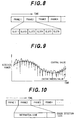
- the received power level measuring units of the mobile stations 61, 62, ... measure pilot signals 31, 32, ... from a plurality of base stations 21, 22, ... on a time division basis in each frame, each pilot signal in each short unit slot as shown in Fig. 8.
- each frame consists of six slots, and at most six pilot signals can be measured in each frame.
- the received power level Q of each pilot signal is instantaneously varied in a short cycle with the lapse of the time, as shown in Fig. 9. Accordingly, the mobile stations 61, 62, ... make measurement of the received power levels Q of the pilot signals for frames corresponding in number to a time, which is sufficiently long compared to the instantaneous variation cycle time of the received power levels Q of the pilot signals when the mobile stations 61, 62, ... are moving, and obtain the center values of the measurements in the slots.
- a mobile station When a mobile station commences communication, it sets a link between it and a base station, the pilot signal from which has the highest received power level center value (hereinafter referred to as primary base station).
- primary base station When a base station is present, the pilot signal from which has a received power level center value higher than the received power level center value of the primary base station pilot signal by a predetermined handover threshold value (hereinafter referred to as secondary base station), the mobile station also sets a link for communication between it and the secondary base station.
- the received power levels Q of pilot signals may be varied with the movement of the mobile stations 61, 62, ....
- the primary and secondary base stations are changed when the base station with the highest received power level center value pilot station is changed, when the secondary base station is no longer qualified as such, and when a different base station has become qualified as the secondary base station.
- the mobile station 61 finds that the pilot signal 31, for instance, has the highest received power level Q and that the difference between the received power levels Q of the pilot signals 32 and 31 is within the handover threshold value, its primary and secondary base stations are constituted by the base stations 21 and 22, respectively.
- the base stations 21 and 22 transmit down line signals 41a and 41b to the mobile station 61, and the mobile station 61 transmits an up line signal 51 to the base stations 21 and 22.
- the mobile station 62 finds that the pilot signal 31 has the highest received power level Q, the base station 21 constitutes the primary base station. In this case, the difference between the received power levels Q of the pilot signals 32 and 31 surpasses the handover threshold value, and no secondary base station of the mobile station 22 is present. At this time, the mobile station 62 makes communication with the base station 21 with the up and down line signals 42 and 52.
- the base stations 21, 22, ... and mobile stations 61, 62, ... transmit data in distinct frames each with a constant amount of data by providing an error detection code in each frame.
- the base stations 21 and 22 each has a power level measuring instrument (not shown) for measuring the corresponding desired wave power level, and they measure desired wave power levels whenever they receive frames transmitted by the mobile stations 61 and 62.
- the mobile stations 61 and 62 each have frame error rate measuring unit (not shown). Whenever the mobile stations 61 and 62 receive frames transmitted from the base stations 21 and 22, they detect errors in frame data codes using error detection codes, and whenever they receive a predetermined number of frames they calculate the rate of frames containing errors (frame error rate).
- the mobile station 61 each have a synthesizer (not shown) for synthesizing the same signals transmitted from a plurality of base stations 21, 22, ..., and synthesize the received down line signals 41a and 41b using the synthesizer.
- the frame error rate measuring unit calculates the frame error rate from the synthesized received signal.
- the mobile station 61 reports the frame error rate obtained from the frame error rate measuring unit to the base stations 21 and 22.
- the mobile station 62 reports the frame error rate to the base station 21.
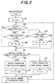
- Fig. 2 is a flow chart illustrating a process executed by a base station for determining a down line transmission power level by receiving the frame error rate report from a mobile station and sending out an up line transmission power level control command.
- this up line transmission power level control command sending process comprises a transmission power level initializing step 201, a frame error rate reception judging step 202, an over predetermined level judging step 203, a transmission power level increasing step 204, an under predetermined level judging step 205, a transmission power level reducing step 206, an over desired power measured result control level judging step 207, a transmission power level reduction control command setting step 208, a transmission power level increase setting step 209, a transmission power level increase control command setting step 210, a transmission power level setting step 211, and a control command sending step 212.
- the base stations 21 and 22 When the base stations 21 and 22 start communication with the mobile stations 61 and 62, they set the down line transmission power level Pf that is determined by the frame error rate to an initial level Pf o (step 201).
- the frame error rate is reported at a predetermined interval from the mobile stations 61 and 62.
- the base stations 21 and 22 receive a newly reported frame error rate (step 202) and find that the rate is higher than a predetermined level range (step 203), the base stations 21 and 22 increase the down line transmission power level Pf determined by the frame error rate by ⁇ P (>0) (step 204).
- the base stations 21 and 22 When the frame error rate is lower than the predetermined rate range (step 205), the base stations 21 and 22 reduce the down line transmission power level Pf determined by the frame error rate by ⁇ P (step 206).
- the base stations 21 and 22 executes a step 207 without changing the down line transmission power level Pf determined by the frame error rate.
- the base stations 21 and 22 provide a level reduction command as the up line transmission power level control command (step 208), and set (Pf+Padd) as the down line transmission power level P (step 209).
- the transmission power level increase Padd is set to a predetermined value.
- the base stations 21 and 22 provide the level increase command as the up line transmission power level control command (step 210), and sets the down line transmission power level P to the level Pf determined by the frame error rate (step 211). Then, the base stations 21 and 22 send an up line transmission power level control command at the down line transmission power level P to the mobile stations 61 and 62 (step 212), and then repeat the routine from the step 202.
- the mobile station 62 controls the up line transmission power level according to the up line transmission power level control command sent out by the base station 21.
- the mobile station 61 which have lines set with respect to the two base stations 21 and 22 at a time, receives the up line transmission power level control commands sent by these base stations 21 and 22. When the two control commands received are different in the content, the mobile station 61 controls the up line transmission power level according to its up line transmission power level reduction control command.
- the primary and secondary base stations receive the same frame error rate report and do the same control of the down line transmission power level Pf determined by the frame error rate.
- the base stations 21 and 22 provide an equal down line transmission power level Pf determined by the frame error rate.
- the down line transmission power level P is set to be higher than the down line transmission power level Pf determined by the frame error rate by the transmission power level increase Padd. It is thus possible to reduce the probability that the mobile stations 61 and 62 fail to receive the up line transmission power level reduction control command, resulting in excessive influence of the up lines on other lines.
- the cellular system adopting the second embodiment of the transmission power level control method has the same construction as the cellular system adopting the first embodiment of the transmission power level control method.
- the sole differences reside in a flow part that the mobile stations 61 and 62 report the received power level Q of pilot signals during the communication to the base stations 21 and 22, and a flow part that the base stations 21 and 22 send the up line transmission power level control command by determining the down line transmission power level P.
- the mobile station 61 measures the received power Q of the pilot signals 31 and 32 sent from the base stations 21 and 22 as the primary and secondary stations, and report the both measured power Q of the pilot signals.
- the time that is spent for the measurement of the received power level Q of the pilot signal is set to be shorter than the time spent for the measurement of the received power level center value of the pilot signal.
- the time interval of the report of the measurement result is set to be shorter than the time interval of updating the primary and secondary base stations.
- the pilot signal measurement signal frame shown in Fig. 8 and the transmission/reception frame shown in Fig. 10 have the same length.
- the mobile stations 61 and 62 measure the received power levels Q of the pilot signals of the base stations 21 and 22 once in each frame shown in Fig. 8, and report the measurement result to the base stations 21 and 22 for each transmission/reception frame of them.
- the influence of instantaneous variations of the received power level Q of the pilot signal is substantially removed from the center value of the received power level Q of the pilot signal used for determining the primary and secondary base stations, but is present in the received power level Q of the pilot signal measured for each frame because of the short measurement time. Therefore, as for the received power level Q of the pilot signal for each frame, unlike the center value, the highest received power level Q may not be of the pilot signal of the primary base station.
- Fig. 3 is a flow chart illustrating a process, in which the base stations 21 and 22 determine the down line transmission power level P by receiving the report of the received power level Q of the pilot signal measured for each frame from the mobile stations 61 and 62 and send an up line transmission line power control command.
- the up line transmission power level control command sending process comprises a transmission power level initializing step 301, a frame error rate reception judging step 302, an over rate range judging step 303, a transmission power level increasing step 304, an under predetermined level judging step 305, a transmission power level reducing step 306, an over desired control level judging step 307, a transmission power level reduction control level control command setting step 308, a maximum own pilot signal reception power level judging step 309, a transmission power level increase setting step 310, a transmission power level increase control command setting step 311, a transmission power level setting step 312, and a control command sending step 313.
- the base stations 21 and 22 When the base stations 21 and 22 start the communication with the mobile stations 61 and 62, they set the down line transmission power level Pf determined by the frame error rate to an initial value Pf o (step 301).
- the frame error rate is reported at a predetermined interval by the mobile stations 61 and 62.
- the base stations 21 and 22 receive a newly reported frame error rate (step 302) and find that the rate is higher than a predetermined rate range (step 303), they increase the down line transmission power level Pf determined by the frame error rate by ⁇ P (step 304).
- the base stations 21 and 22 When the rate is lower than the predetermined rate range (step 305), the base stations 21 and 22 reduce the down line transmission power level Pf determined by the frame error rate by ⁇ P (step 306).
- the base stations 21 and 22 leave the down line transmission power level Pf determined by the frame error rate as such, and go to a step 307.
- the base stations 21 and 22 provide a level reduction command as the up line transmission power level control command (step 308).
- the base stations 21 and 22 set (Pf+Padd) as the down line transmission power level (step 310).
- the transmission power level increase Padd is set to a predetermined value.
- the base stations 21 and 22 When it is found in the step 307 the measurement result D of the up line desired wave power level is lower than the predetermined control level T, the base stations 21 and 22 provide a level increase command as the up line transmission power level control command (step 311), and set the down line transmission power level P to the down line transmission power level Pf determined by the frame error rate (step 312).
- the base stations 21 and 22 send the up line transmission power level control command at the down line transmission power level P to the mobile stations 61 and 62 (step 313), and repeat the routine from the step 302.
- the base stations 21 and 22 when the base stations 21 and 22 send the up line transmission power level reduction control command to the mobile stations 61 and 62, they increase the down line transmission power level P by the transmission power level increase Padd when and only when otherwise it is highly probable that the mobile stations 61 and 62 fail to receive the up line transmission power level reduction control command because the received power level Q of the own pilot signal is not the highest level.
- the base stations 21 and 22 when they send the up line transmission power level reduction control command to the mobile stations 61 and 62, they increase the down line transmission power level P by the transmission power level increase Padd when and only when otherwise it is highly probable that the mobile stations 61 and 62 fail to receive the up line transmission power level reduction control command because the received power level Q of the own pilot signal is not the highest level.
- the cellular system adopting the third embodiment of the transmission power level control method has the same construction as the cellular system adopting the second embodiment of the transmission level control method, and also the flow part, in which the base stations send the up line transmission power level control command by determining the down line transmission power level P as shown by the flow chart of Fig. 3.
- a difference resides in the way of determining the transmission power level increase Padd.
- the transmission power level increase Padd is determined on the basis of the received power level Q of the pilot signal of the own station and that of the other base station.
- Fig. 4 is a flow chart illustrating a process of determining the transmission power level increase Padd in the third embodiment of the transmission power level control method.
- the determined process of the transmission power level increase Padd comprises a pilot signal received power level report receiving step 401, an own pilot signal received power level setting step 402, an other station pilot signal received power level setting step 403, a counter initializing step 404, a maximum received power level setting step 405, a counter judging step 406, a counter incrementing step 407, a received power level comparing step 408, and a transmission power level increase setting step 409.
- the base stations 21 and 22 receive the reports on the primary and secondary base station pilot signal received power levels Q from the mobile stations 61 and 62 (step 401).
- the base stations 21 and 22 then set a count i to "1" (step 404), and set the maximum pilot signal received power level Q max to Q i (step 405).
- the count i is not equal to (N-1) (step 406)
- the base stations 21 and 22 add "1" to the count i (step 407).
- the base stations 21 and 22 set the maximum level Q max to Q i (step 408).
- the base stations 21 and 22 repeat the routine from the step 406.
- the base stations 21 and 22 sets the transmission power level increase Padd to (Q max -Q o ) (step 409), and brings an end to the routine.
- the third embodiment of the transmission power level control method it is possible to obtain the same effects as obtainable with the second embodiment of the transmission power level control method.
- the down line transmission power level P of the base station with the highest pilot signal received power level Q i is increased by an amount corresponding to the amount, by which the own pilot signal received power level Q o is lower, i.e., the transmission is higher.
- the measured result D of the desired wave power level in the mobile stations 61 and 62 is made the same as the up line transmission power level control command from the other base station.
- the down line transmission power level P is increased by an amount necessary for reducing the probability that the mobile stations 61 and 62 fail to receive the up line transmission power level reduction control command. It is thus possible to further reduce the down line interference wave power level increase.
- the cellular system adopting the fourth embodiment of the transmission power level control method like the cellular system adopting the first embodiment of the transmission power level control method, has the construction as shown in Fig. 1.
- the base stations 21 and 22 send their pilot signals 31 and 32
- the mobile stations 61 and 62 measure the center value of the received power level of the pilot signals 31 and 32
- the primary and secondary base stations are determined for each of the mobile stations 61 and 62 according to the result of measurement.
- the base stations 21 and 22 each have a measuring unit (not shown) for measuring the up line desired wave power level.
- the base stations 21 and 22 send the signal at a predetermined power transmission level P to the mobile stations 61 and 62 irrespective of whether the soft handover is being executed.
- the base stations 21 and 22 which are the primary and secondary base stations of the mobile station 61 during the soft handover execution, measure the up line desired wave power level of the Mobile station 61 and report the result of measurement to a switching station 71.
- Fig. 5 is a flow chart illustrating a process, in which the switching station 71 determines the up line transmission power level control commands by receiving the desired wave power level measurement result report and reports the determined control command to the base stations 21 and 22.
- the up line transmission power level control command reporting process comprises a desired wave power level measurement result report receiving step 501, a desired control level report receiving step 502, a count initializing step 503, a measurement result/desired control level difference judging step 504, a count end judging step 505, a count incrementing step 506, a transmission power level increase control command setting step 507, a transmission power level reduction control command 508, and a control command reporting step 509.
- the desired control level T i of the desired power level is fixed and common to the base stations 21 and 22.
- the switching station 71 sets the count i to "0" (step 503). Then, in a step 504 the switching station 71 checks the difference (D i -T i ) between the measurement result D i of the desired wave power level of an i-th base station and the desired control level T i of the desired wave power level. When (D i -T i ) is not greater than "0", the count i is compared to (N-1) (step 505). When the compared values are not equal, "1" is added to the count i (step 506), and the routine is repeated from the step 504.
- the switching station 71 makes the up line transmission power level control command to be a level increase command (step 507).
- the switching station 71 makes the up line transmission power level control command to be a level reduction command (step 508).
- the switching station 71 reports the determined up line transmission power level control command to the primary and secondary base stations (step 509).
- the base stations 21 and 22 report the up line transmission power level control command reported from the switching station 71 via the down line to the mobile stations 61 and 62, and the mobile stations 61 and 62 control the up line transmission power level according to the control command.
- the primary and secondary base stations send the same up line transmission power level control commands.
- the up line transmission power level can be controlled to the desired wave power level without possibility of excessive interference wave power with respect to either of the base stations 21 and 22 even with failure of reception of the other command. In this way, it is possible to increase the up line capacity.
- the down line transmission power level P is set to a fixed level.
- the mobile stations 61 and 62 measure the frame error rate, and the base stations 212 and 22 receive the reports of the measurement and control the down line transmission power level according to the report.
- the cellular system adopting the fifth embodiment of the transmission power level control method like the cellular system adopting the first embodiment of the transmission Power level control method, has the same construction as shown in Fig. 1.
- the base stations 21 and 22 send the pilot signals 31 and 32
- the mobile stations 61 and 62 measure the center value of the received power level of the pilot signals 31 and 32
- the primary and secondary base stations are determined for communication with each of the mobile stations 61 and 62 according to the result of measurement.
- the base stations 21 and 22 each have a measuring unit (not shown) for measuring the up line desired wave power level.
- the base stations 21 and 22 send signal at a down line transmission power level P to the mobile stations 61 and 62 irrespective of whether the soft handover is being executed.
- the base stations 21 and 22 each set a level reduction command as a tentative transmission power level control signal.
- the difference (D i -T i ) is less than "0"
- the base stations set a level increase command as the tentative control command.
- the tentative control commands are reported to the switching station 71.
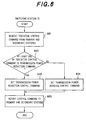
- Fig. 6 is a flow chart illustrating a process, in which the switching station 71 determines the up line transmission power level control command by receiving the reports of tentative control commands from the base stations 21 and 22 and reporting the command to the base stations 21 and 22.
- the up line transmission power level control command reporting process comprises a tentative control command report receiving step 601, a transmission power level reduction judging step 602, a transmission power level reduction control command setting step 603, a transmission power level increase control command setting step 604, and a control command reporting step 605.
- the fifth embodiment of the transmission power level control method will now be described together with the operation of the cellular system.
- the switching station 71 receives reports of the tentative control commands from the primary and secondary base stations (step 601). Then, when it is found in the step 602 that at least one of the tentative control commands is a level reduction command, the switching station 71 determines the up line transmission power level control command to be a level reduction command (step 603). When all the tentative control commands are level increase commands, the switching station 71 determines the up line transmission power level control command to be a level increase command (step 604). The switching station 71 reports the determined up line transmission power level control command to the base stations 21 and 22 as the primary and secondary base stations, respectively (step 605).
- the base stations 21 and 22 report the up line transmission power level control command reported from the switching station 71 via the down line to the mobile stations 61 and 62, and the mobile stations 61 and 62 control the up line transmission power level according to the control command.
- the primary and secondary base stations send the same up line transmission power level control command.
- the up line transmission power level can be controlled to the desired wave power level without possibility of excessive interference wave power with respect to either of the base stations 21 and 22 even with failure of reception of other commands. In this way, it is possible to increase the up line capacity.
- the cellular system adopting the sixth embodiment of the transmission power level control method like the first embodiment of the transmission power level control method, has the construction shown in Fig. 1.
- the base stations 21 and 22 send their pilot signals 31 and 32, and the mobile stations 61 and 62 measure the center value of the received power level of the pilot signals and determine the primary and secondary base stations for communication with respect to each of the mobile stations 61 and 62 according to the result of measurement.
- the base stations 21 and 22 each have a measuring unit (not shown) for measuring the up line desired wave power level.
- the base stations 21 and 22 send the communication signal at a predetermined down line transmission power level P to the mobile stations 61 and 62 irrespective of whether soft handover is being executed.
- the switching station 71 receives the reports of the desired wave power level measurement result Di and determines the up line transmission power level and reports the determined command to the base stations 21 and 22.
- the mobile station 61 measures the received power levels Q of the pilot signals 31 and 32 sent from the base stations 21 and 22 as the primary and secondary base stations, and reports both the measured received power levels Q to each of the base stations 21 and 22.
- the time spent for the measurement of the received power levels Q of the pilot signals is set to be shorter than the time spent for measuring the center value of each of these received power levels of the pilot signals.
- the interval of reporting the result of measurement is set to be shorter than the interval of updating the primary and secondary base stations.
- the pilot signal measurement frame shown in Fig. 6 and the transmission/reception frame shown in Fig. 10 are the same in length, and the mobile stations 61 and 62 measure the received power levels Q of the pilot signals of the base stations 21 and 22 once in each frame shown in Fig. 8 and report the result of measurement to the base stations 21 and 22 for each transmission/reception frame of the mobile stations 61 and 62. This means that the received power level Q of the pilot signal from the primary base station measured for each frame may not be highest.
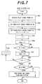
- Fig. 7 is a flow chart illustrating a process, in which the base stations 21 and 22 determine whether they send signal during the soft handover execution.
- the process of determining the signal sending during the soft handover execution comprises a pilot signal received power level report receiving step 701, an own pilot signal received power level setting step 702, an other station pilot signal received power level setting step 703, a count initializing step 704, a maximum received power level setting step 705, a received power level comparing step 706, a maximum received power level setting step 707, a count judging step 708, a count incrementing step 709, a received power level comparing step 710, and a down line signal sending step 711.
- the base stations 21 and 22 then set the counter i to "1" and set the maximum pilot signal received power level Q max to "0" (step 705).
- the base stations 21 and 22 set the maximum level Q max to Q i (step 707), and compares the count i and (N-1). When the two are not equal, the base stations 21 and 22 add count i to "1" (step 709).
- the routine is then repeated from the step 706.
- the base stations 21 and 22 execute a step 708.
- the base stations 21 and 22 execute a step 710 of comparing the maximum level Q max with the own pilot signal received power level Q o .
- the own station sends down line signals 41a, 41b and 42 (step 711).
- the other base station sends signals, while the own station does not.
- the base stations 21 and 22 receive reports of the received power levels Q of the pilot signals of the primary and secondary base stations from the mobile stations 61 and 62, and when the own pilot signal received power level Q is highest, they report the up line transmission power level control command reported from the switching station 71 via the down line to the mobile stations 61 and 62 to let the mobile stations 61 and 62 control the up line transmission power level according to the up line transmission power level control command.
- the up line transmission power level can be controlled to the desired wave power level without possibility of excessive interference wave power with respect to either of the base stations 21 and 22 even with failure of reception of the other commands, thus permitting the up line capacity to be increased.
- the desired control value in the up line transmission power level control need neither be common to all the base stations nor be fixed, that is, it is possible to control the desired control value according to the interference wave power levels in the base stations.
- the base stations measure the ratio between the desired wave power level and the interference wave power level instead of measuring the desired wave power level and determine the transmission power level control command to the mobile stations such that the power level ratio between the desired and interference waves is a constant.
- the present invention it is possible to prevent mobile stations from making transmission via the up line at an excessive transmission power level and permit increasing the up line capacity during the handover execution in any of the cases when adopting the transmission power level control method of making the transmission power levels in the base stations to be equal, when no down line transmission power level control is made and when only a single base station transmits signal via the down line.
Description
- The present invention relates to a cellular system, in which mobile stations communicate with one another via base stations located in respective service areas or cells. More particularly, the present invention concerns a method of transmission power control in a cellular system, which provides hand-over control permitting continuous communication of a mobile station and also transmission power control when the mobile station is moving between two base stations.
- Some CDMA (code division multiplexed access) cellular system adopts a technique called soft hand-over system, inter-cell lines are switched when a mobile station moving between cells approaches the borderline between the cells, while continuing simultaneous communications with a plurality of base stations. This technique is detailed in United States Patent No. 5,101,501 (Gilhousen et al., "Method and System for Providing a Soft Handoff in Communications in a CDMA Cellular Telephone System", Mar. 31, 1992).
- In the CDMA system, the same frequency is used by a plurality of lines, and the reception power (or desired wave power) of a signal on a certain line constitutes interference wave power to other lines. Therefore, in an up line, via which the signal is transmitted by a mobile station and received by a base station, increase of the desired wave power beyond a predetermined level results in an interference power increase, thus reducing the line capacity. To prevent this, the transmission power on the up line of the mobile station should be stringently controlled, In such an up line transmission power control, the base station measures the desired wave power and, when the desired wave power is high, it sends out an up line transmission power reduction control command to the mobile station, while sending out an up line transmission power increase control command to the mobile station when the desired wave power is low. This method of transmission power control is detailed in United States Patent No. 5,056,109 (Gilhousen et al, "Method and Apparatus for Controlling Transmission Power in a CDMA Cellular Mobile Telephone System", Oct. 8, 1991).
- In up line transmission power control during execution of the soft handover, a plurality of base stations measure the desired wave power from a mobile station, and send independent up line transmission power control commands to the mobile station. When the mobile station receives different control commands, it preferentially follows a transmission power reduction control command. This method is described in TIA/EIA Interim Standard, "Mobile Station-Base Station Compatibility Standard for Dual-Mode Wideband Spread Spectrum Cellular System" and TIA/EIA/95-A, Telecommunications Industry Association, May 1995, "6.6.6.2.7.2 Reverse Traffic Channel Power Control during Soft Handoff". As shown, when control commands from base stations are different, a transmission power reduction control command is preferentially followed, thus preventing the surpassing of a desired value of control by the desired wave power in any base station and realizing high line capacity of the up line. In this method, it is important to reduce the probability of failure of the transmission power reduction control signal reception by the mobile station.
- In the down line, via which the signal is transmitted from the base station and received by the mobile station, a high line capacity is realized by transmission power control such that the ratio between the desired wave power and the interference wave power is a predetermined value. In the up line transmission power control, an up line transmission power control command is transmitted to the mobile station to the mobile station by utilizing the down line as described before, and during the soft handover execution the down line transmission power should be controlled such that the mobile station can receive up line transmission power control commands sent out from a plurality of base stations.
- A conceivable method to this end is to control the down line transmission power such that the desired power levels from the base stations are equal at the mobile station. In this method, base stations with higher transmission losses up to the mobile station set correspondingly increased transmission power. Increasing the transmission power, however, increases the interference wave power and reduces the down line capacity. The down line capacity reduction can be suppressed by controlling the transmission power levels of the base stations to be equal. This method is described in Anderson, "Tuning the Micro Diversity Performance in a DS-CDMA System", Proc. IEEE 44th Vehicular Technology Conference, pp. 41-45, June 1994.
- In the above prior art transmission power control method, however, the desired wave power sent from a base station with a high transmission loss to the mobile station is low. In this case, the probability of failure of the up line transmission power control command from the base station and also the probability of failure of the up line transmission power reduction control command by the mobile station are increased.
- Instantaneous transmission loss variations vary with the frequency. In a cellular system in which different frequencies are used for the up and down lines, therefore, the transmission losses in the up and down lines are different. As a result, due to the low up line transmission loss when the transmission power reduction control command is sent with the desired control value at the base station, a case may arise that due to a high transmission loss in the down line the desired wave power in the mobile station is low, resulting in a failure of the transmission power reduction control command by the mobile station.
- When the control commands from all the other base stations are transmission power increase control commands at this time, the mobile station increases the transmission power. In consequence, the desired wave power becomes excessive in the base station, resulting in increase of the interference wave power and reduction of the up line capacity of that base station compared to the case when the transmission control power is executed without control command reception failure. In such a transmission power control method, in which the reception power levels from the base stations are made equal, the probability of receiving all up line transmission power control commands is reduced, giving rise to a problem of reducing the up line capacity.
- In EP-A-0 671 819, a cellular mobile radio system is described wherein the mobile stations comprise a means for monitoring the power control bits to identify the base station sending the greater number of bits over a transmit frame and for indicating that that base station has received the higher average power signal over the transmit frame. WO 94/00927 relates to a system wherein a base station communicating to a mobile station increases the transmission power level of a handoff command when required. In the system described, the base station detects when handoff is required, and transmits the handoff command at a first power level. If the handoff command does not reach the mobile station, either after the elapse of a predetermined time period or some other predetermined triggering event, the base station transmits the handoff command at a second, increased power level. WO 95/12297 discloses a method and apparatus for reducing the average downlink transmitted power from base stations during soft handoff command transmission.
- An object of the present invention is to provide a transmission power control method, which can solve the above problems in the cellular systems and control the up line transmission power with increase of the up line capacity.
- The object of the present invention is achieved with the features of the claims.
- According to one aspect of the present invention, there is provided a cellular system involving a plurality of cells, base stations each located in each of the cells, and a plurality of mobile stations present in the cells, the mobile stations each being able to have a link or links set for communication with one or a plurality of the base stations, wherein: when one of the mobile stations have links set with respect to a plurality of the base stations, the plurality of base stations each measure the received power level of signal transmitted from a mobile station, determine a control command for controlling the transmission power level of signal transmitted by the mobile station, and send the control command to the mobile station, and the mobile station receives the control commands from the plurality of base stations and controls the transmission power level according to a control command for making the transmission power level minimum, and when one of the base stations send a control command for reducing the transmission power level to the mobile stations, the transmission power level of signal sent by the base station is increased with respect to the other cases.
- The base stations each send a pilot signal, one of the mobile stations with links set with respect to a plurality of the base stations measures the received power levels of the pilot signals of the plurality of base stations and reports all the received power levels of the pilot signals to all of plurality of base stations, and when each of the base stations send a control command for reducing the transmission power level and the received power level of the own pilot signal is not highest among the received power levels of the pilot signals of the plurality of base stations, the transmission power level sent by the base station is increased with respect to the other cases.
- The base stations each send a pilot signal, one of the mobile stations with links set with respect to a plurality of the base stations measures the received power levels of the pilot signals of the plurality of base stations and reports all the received power levels of the pilot signals to the plurality of the base stations, and when each of the base stations send a control command for reducing the transmission power level and the received power level of the own pilot signal is not highest among the received power levels of the pilot signals of the plurality of base stations, the transmission power level sent by the base station is increased by an amount corresponding to the ratio between the highest received power level one of the pilot signals of the plurality of base stations and the received power level of the own pilot signal.
- According to another aspect of the present invention, there is provided a cellular system involving a plurality of cells, base stations each located in each of the cells, a switching station connected to the base stations, and mobile stations present in the cells, the mobile stations being able to have a link or links set for communication with one or a plurality of the base stations, a transmission power level control method, wherein: when one of the mobile stations has links set with respect to a plurality of the base stations, the plurality of base stations each measure the received power level of signal transmission from the base station, the switching station determines a control command for controlling the transmission power level of signal transmitted by the mobile station, and the plurality of base stations send the determined control signal to the mobile station, and the mobile station receives the control command and controls the transmission power level on the basis of the received control command.
- When the switching station determines the control signal for controlling the transmission power level of signal transmitted by the mobile station on the basis of the measurement result in the plurality of base stations, the base stations each tentatively determine a control command for controlling the transmission power level of signal transmitted by the mobile station, and the switching station determines one of the control commands tentatively determined by the plurality of base stations that minimizes the transmission power level of signal transmitted by the mobile station.
- The base stations each send a pilot signal, while one of the mobile stations have links set with respect to a plurality of the base stations, the mobile station measures the received power levels of the pilot signals of the plurality of base stations and reports all the received power levels to the plurality of base stations, and the base station sending the highest received power level pilot signal sends the determined control signal to the mobile station.
- Other objects and features will be clarified from the following description with reference to attached drawings.
-
- Fig. 1 is a schematic view showing a cellular system which adopts a first embodiment of the transmission power control method according to the present invention;
- Fig. 2 is a flow chart illustrating a process executed by a base station for determining a down line transmission power level by receiving the frame error rate report from a mobile station and sending out an up line transmission power level control command;
- Fig. 3 is a flow chart illustrating a process,
in which the
base stations mobile stations - Fig. 4 is a flow chart illustrating a process of determining the transmission power level increase Padd in the third embodiment of the transmission power level control method;
- Fig. 5 is a flow chart illustrating a process,
in which the
switching station 71 determines the up line transmission power level control commands by receiving the desired wave power level measurement result report and reports the determined control command to thebase stations - Fig. 6 is a flow chart illustrating a process,
in which the
switching station 71 determines the up line transmission power level control command by receiving the reports of tentative control commands from thebase stations base stations - Fig. 7 is a flow chart illustrating a process,
in which the
base stations - Fig. 8 is an example of frame structure for measuring the pilot signal received power by the mobile station in the cellular system in Fig. 1;
- Fig. 9 is a drawing for explaining the instantaneous value and the center value of the received power; and
- Fig. 10 is an example of frame structure for transmitting/receiving the information between the base station and the mobile station in the cellular system in Fig. 1.
-
- Fig. 1 is a schematic view showing a cellular system which adopts a first embodiment of the transmission power control method according to the present invention. In this cellular system, the service area consists of a plurality of divisions or
cells respective base stations Mobile stations base stations switching station 71, which is in turn connected to the rest of a network with the other switching stations (not shown). Although not shown, it is assumed that this cellular system includes many other base stations and that many mobile stations are present in each cell. - The
base stations respective pilot signals mobile stations pilot signals mobile stations measure pilot signals base stations - When the
mobile stations mobile stations mobile stations - When a mobile station commences communication, it sets a link between it and a base station, the pilot signal from which has the highest received power level center value (hereinafter referred to as primary base station). When a base station is present, the pilot signal from which has a received power level center value higher than the received power level center value of the primary base station pilot signal by a predetermined handover threshold value (hereinafter referred to as secondary base station), the mobile station also sets a link for communication between it and the secondary base station. During communication, the received power levels Q of pilot signals may be varied with the movement of the
mobile stations - When the
mobile station 61 finds that thepilot signal 31, for instance, has the highest received power level Q and that the difference between the received power levels Q of the pilot signals 32 and 31 is within the handover threshold value, its primary and secondary base stations are constituted by thebase stations base stations mobile station 61, and themobile station 61 transmits an upline signal 51 to thebase stations - On the other hand, when the
mobile station 62 finds that thepilot signal 31 has the highest received power level Q, thebase station 21 constitutes the primary base station. In this case, the difference between the received power levels Q of the pilot signals 32 and 31 surpasses the handover threshold value, and no secondary base station of themobile station 22 is present. At this time, themobile station 62 makes communication with thebase station 21 with the up and down line signals 42 and 52. - In this cellular system, the
base stations mobile stations - The
base stations mobile stations - The
mobile stations mobile stations base stations - The
base stations mobile station 61 executing the soft handover, send out down line signals 41a and 41b, which are the same data except for up line transmission power level control command, to themobile station 61. Themobile station 61 each have a synthesizer (not shown) for synthesizing the same signals transmitted from a plurality ofbase stations mobile station 61 reports the frame error rate obtained from the frame error rate measuring unit to thebase stations mobile station 62 reports the frame error rate to thebase station 21. - The flow chart will now be explained. In the flow chart, the power level is in decibels.
- Fig. 2 is a flow chart illustrating a process executed by a base station for determining a down line transmission power level by receiving the frame error rate report from a mobile station and sending out an up line transmission power level control command. Referring to Fig. 2, this up line transmission power level control command sending process comprises a transmission power
level initializing step 201, a frame error ratereception judging step 202, an over predeterminedlevel judging step 203, a transmission powerlevel increasing step 204, an under predeterminedlevel judging step 205, a transmission powerlevel reducing step 206, an over desired power measured result controllevel judging step 207, a transmission power level reduction controlcommand setting step 208, a transmission power levelincrease setting step 209, a transmission power level increase controlcommand setting step 210, a transmission powerlevel setting step 211, and a controlcommand sending step 212. - The above first embodiment of the transmission power level control method will now be described along with the operation of the cellular system.
- When the
base stations mobile stations mobile stations base stations base stations base stations step 202 that no newly reported frame error rate is present, thebase stations step 207 without changing the down line transmission power level Pf determined by the frame error rate. - When it is found in the
step 207 that the result D of measurement of the up line desired wave power level that is measured for every frame is higher than a predetermined desired control level T, thebase stations base stations base stations mobile stations 61 and 62 (step 212), and then repeat the routine from thestep 202. - The
mobile station 62 controls the up line transmission power level according to the up line transmission power level control command sent out by thebase station 21. Themobile station 61, on the other hand, which have lines set with respect to the twobase stations base stations mobile station 61 controls the up line transmission power level according to its up line transmission power level reduction control command. - In the first embodiment of the transmission power level control method, during the soft handover execution the primary and secondary base stations receive the same frame error rate report and do the same control of the down line transmission power level Pf determined by the frame error rate. Thus, the
base stations mobile stations mobile stations - A second embodiment of the transmission power level control method will now be described.
- The cellular system adopting the second embodiment of the transmission power level control method, has the same construction as the cellular system adopting the first embodiment of the transmission power level control method. The sole differences reside in a flow part that the
mobile stations base stations base stations - The
mobile station 61 measures the received power Q of the pilot signals 31 and 32 sent from thebase stations - The time that is spent for the measurement of the received power level Q of the pilot signal, is set to be shorter than the time spent for the measurement of the received power level center value of the pilot signal. The time interval of the report of the measurement result is set to be shorter than the time interval of updating the primary and secondary base stations. In this embodiment, the pilot signal measurement signal frame shown in Fig. 8 and the transmission/reception frame shown in Fig. 10 have the same length. The
mobile stations base stations base stations - With this arrangement, the influence of instantaneous variations of the received power level Q of the pilot signal is substantially removed from the center value of the received power level Q of the pilot signal used for determining the primary and secondary base stations, but is present in the received power level Q of the pilot signal measured for each frame because of the short measurement time. Therefore, as for the received power level Q of the pilot signal for each frame, unlike the center value, the highest received power level Q may not be of the pilot signal of the primary base station.
- Fig. 3 is a flow chart illustrating a process, in which the
base stations mobile stations level initializing step 301, a frame error ratereception judging step 302, an over raterange judging step 303, a transmission powerlevel increasing step 304, an under predeterminedlevel judging step 305, a transmission powerlevel reducing step 306, an over desired controllevel judging step 307, a transmission power level reduction control level controlcommand setting step 308, a maximum own pilot signal reception powerlevel judging step 309, a transmission power levelincrease setting step 310, a transmission power level increase controlcommand setting step 311, a transmission powerlevel setting step 312, and a controlcommand sending step 313. - The second embodiment of the transmission power level control method will now be described together with the operation of the cellular system.
- When the
base stations mobile stations mobile stations base stations base stations step 302 that no newly reported frame error rate is present, thebase stations step 307. - When it is determined in the
step 307 that the measurement result D of the up line desired wave power level measured for very frame is higher than the desired control level T, thebase stations step 309 that the received power level Q of the own pilot signal is not maximum, thebase stations step 309 that the received power level Q of the own pilot signal is the highest level, thebase stations - When it is found in the
step 307 the measurement result D of the up line desired wave power level is lower than the predetermined control level T, thebase stations base stations mobile stations 61 and 62 (step 313), and repeat the routine from thestep 302. - In the second embodiment of the transmission power level control method, when the
base stations mobile stations mobile stations mobile station - A third embodiment of the transmission power level control method will now be described.
- The cellular system adopting the third embodiment of the transmission power level control method has the same construction as the cellular system adopting the second embodiment of the transmission level control method, and also the flow part, in which the base stations send the up line transmission power level control command by determining the down line transmission power level P as shown by the flow chart of Fig. 3. A difference resides in the way of determining the transmission power level increase Padd. Specifically, the transmission power level increase Padd is determined on the basis of the received power level Q of the pilot signal of the own station and that of the other base station.
- Fig. 4 is a flow chart illustrating a process of determining the transmission power level increase Padd in the third embodiment of the transmission power level control method. Referring to Fig. 4, the determined process of the transmission power level increase Padd comprises a pilot signal received power level
report receiving step 401, an own pilot signal received powerlevel setting step 402, an other station pilot signal received powerlevel setting step 403, acounter initializing step 404, a maximum received powerlevel setting step 405, acounter judging step 406, acounter incrementing step 407, a received powerlevel comparing step 408, and a transmission power levelincrease setting step 409. - The third embodiment of the transmission power level control method will now be described together with the operation of the cellular system.
- In the third embodiment of the transmission power level control method, like the second embodiment of the transmission power level control method, the
base stations mobile stations 61 and 62 (step 401). Thebase stations mobile stations - The
base stations base stations base stations base stations step 406. When it is found in thestep 406 that the count i is equal to (N-1), thebase stations - With the third embodiment of the transmission power level control method, it is possible to obtain the same effects as obtainable with the second embodiment of the transmission power level control method. In the third embodiment of the transmission power level control method, when the own pilot signal received power level Qo is not highest, dictating the sending of the up line transmission power level reduction control command to the
mobile stations mobile stations mobile stations - A fourth embodiment of the transmission power level control method will now be described.
- The cellular system adopting the fourth embodiment of the transmission power level control method, like the cellular system adopting the first embodiment of the transmission power level control method, has the construction as shown in Fig. 1.
- Also, in the fourth embodiment of the transmission power level control method, like the first embodiment of the transmission power level control method, the
base stations mobile stations mobile stations - In this cellular system, the
base stations - In the down line, the
base stations mobile stations - The
base stations mobile station 61 during the soft handover execution, measure the up line desired wave power level of theMobile station 61 and report the result of measurement to a switchingstation 71. - Fig. 5 is a flow chart illustrating a process, in which the switching
station 71 determines the up line transmission power level control commands by receiving the desired wave power level measurement result report and reports the determined control command to thebase stations report receiving step 501, a desired control levelreport receiving step 502, acount initializing step 503, a measurement result/desired control leveldifference judging step 504, a countend judging step 505, acount incrementing step 506, a transmission power level increase controlcommand setting step 507, a transmission power levelreduction control command 508, and a controlcommand reporting step 509. - The fourth embodiment of the transmission power level control method will now be described together with the operation of the cellular system.
- The switching
station 71 receives the reports of the desired wave power level measurement result Di (i=0,...,N-1) from thebase stations 21 and 22 (step 501). The switchingstation 71 also receives the reports of the desired control level Ti (i=0,...,N-1) of the desired wave power level from thebase stations 21 and 22 (step 502). The desired control level Ti of the desired power level is fixed and common to thebase stations - The switching
station 71 then sets the count i to "0" (step 503). Then, in astep 504 the switchingstation 71 checks the difference (Di-Ti) between the measurement result Di of the desired wave power level of an i-th base station and the desired control level Ti of the desired wave power level. When (Di-Ti) is not greater than "0", the count i is compared to (N-1) (step 505). When the compared values are not equal, "1" is added to the count i (step 506), and the routine is repeated from thestep 504. When it is found in thestep 505 that the count i and (N-1) are equal, the switchingstation 71 makes the up line transmission power level control command to be a level increase command (step 507). When it is not found in thestep 504 that (Di -Ti) is greater than "0", the switchingstation 71 makes the up line transmission power level control command to be a level reduction command (step 508). The switchingstation 71 reports the determined up line transmission power level control command to the primary and secondary base stations (step 509). - The
base stations station 71 via the down line to themobile stations mobile stations - In the fourth embodiment of the transmission power level control method, the primary and secondary base stations send the same up line transmission power level control commands. Thus, when at least either one of the commands is received, the up line transmission power level can be controlled to the desired wave power level without possibility of excessive interference wave power with respect to either of the
base stations - In the fourth embodiment of the transmission power level control method, the down line transmission power level P is set to a fixed level. However, as described before in connection with the first embodiment of the transmission power level control method, the
mobile stations base stations - A fifth embodiment of the transmission power level control method will be described.
- The cellular system adopting the fifth embodiment of the transmission power level control method, like the cellular system adopting the first embodiment of the transmission Power level control method, has the same construction as shown in Fig. 1.
- Also, like the cellular system adopting the first embodiment of the transmission power level control method, the
base stations mobile stations mobile stations - In the cellular system adopting the fifth embodiment of the transmission power level control method, the
base stations - In the down line, the
base stations mobile stations - When the difference (Di-Ti) between the desired wave power level measurement result Di and the desired control level Ti of the desired wave power is greater than "0", the
base stations station 71. - Fig. 6 is a flow chart illustrating a process, in which the switching
station 71 determines the up line transmission power level control command by receiving the reports of tentative control commands from thebase stations base stations report receiving step 601, a transmission power levelreduction judging step 602, a transmission power level reduction controlcommand setting step 603, a transmission power level increase controlcommand setting step 604, and a controlcommand reporting step 605. - The fifth embodiment of the transmission power level control method will now be described together with the operation of the cellular system.
- The switching
station 71 receives reports of the tentative control commands from the primary and secondary base stations (step 601). Then, when it is found in thestep 602 that at least one of the tentative control commands is a level reduction command, the switchingstation 71 determines the up line transmission power level control command to be a level reduction command (step 603). When all the tentative control commands are level increase commands, the switchingstation 71 determines the up line transmission power level control command to be a level increase command (step 604). The switchingstation 71 reports the determined up line transmission power level control command to thebase stations - The
base stations station 71 via the down line to themobile stations mobile stations - In the fifth embodiment of the transmission power level control method, the primary and secondary base stations send the same up line transmission power level control command. Thus, when at least either one of the commands is received, the up line transmission power level can be controlled to the desired wave power level without possibility of excessive interference wave power with respect to either of the
base stations - A sixth embodiment of the transmission power level control method will now be described.
- The cellular system adopting the sixth embodiment of the transmission power level control method, like the first embodiment of the transmission power level control method, has the construction shown in Fig. 1.
- Also, like the first embodiment of the transmission power level control method, the
base stations mobile stations mobile stations - In the cellular system adopting the sixth embodiment of the transmission power level control method, the
base stations - In the down line, the
base stations mobile stations - The
base stations mobile station 61 executing the handover, measure the up line desired wave power level of themobile station 61 and report the result of measurement to the switchingstation 71. - The switching
station 71 receives the reports of the desired wave power level measurement result Di and determines the up line transmission power level and reports the determined command to thebase stations - The
mobile station 61 measures the received power levels Q of the pilot signals 31 and 32 sent from thebase stations base stations - The time spent for the measurement of the received power levels Q of the pilot signals is set to be shorter than the time spent for measuring the center value of each of these received power levels of the pilot signals. The interval of reporting the result of measurement is set to be shorter than the interval of updating the primary and secondary base stations. In the sixth embodiment of the transmission power level control method, like the second embodiment of the transmission power level control method, the pilot signal measurement frame shown in Fig. 6 and the transmission/reception frame shown in Fig. 10, are the same in length, and the
mobile stations base stations base stations mobile stations - Fig. 7 is a flow chart illustrating a process, in which the
base stations report receiving step 701, an own pilot signal received powerlevel setting step 702, an other station pilot signal received powerlevel setting step 703, acount initializing step 704, a maximum received powerlevel setting step 705, a received powerlevel comparing step 706, a maximum received powerlevel setting step 707, acount judging step 708, acount incrementing step 709, a received powerlevel comparing step 710, and a down linesignal sending step 711. - The sixth embodiment of the transmission power level control method will now be described together with the operation of the cellular system.
- In the sixth embodiment of the transmission power level control method, like the third embodiment of the transmission power level control method, the
base stations mobile stations 61 and 62 (step 701). Then, thebase stations mobile stations - The
base stations step 706 that the pilot signal received power level Qi is higher the maximum level Qmax, thebase stations base stations step 706. When it is found in thestep 706 that the pilot signal received power level Qi is lower than the maximum level Qmax, thebase stations step 708. - When it is found in the
step 708 that the count i is equal to (N-1), thebase stations step 710 of comparing the maximum level Qmax with the own pilot signal received power level Qo. When the own pilot signal received power level Qo is higher than the maximum level Qmax, the own station sends down line signals 41a, 41b and 42 (step 711). When it is found in thestep 710 that the own pilot signal received power level Qo is lower than the maximum level Qmax, the other base station sends signals, while the own station does not. - As shown, during soft handover execution the
base stations mobile stations station 71 via the down line to themobile stations mobile stations - With the sixth embodiment of the transmission power level control method, even when adopted by a cellular system in which only either one of the primary and secondary base stations send down line signal according to the pilot signal received power levels Q in the
mobile stations base stations - In all the above embodiments, the desired control value in the up line transmission power level control need neither be common to all the base stations nor be fixed, that is, it is possible to control the desired control value according to the interference wave power levels in the base stations. For the up line transmission power level control, it is also possible that the base stations measure the ratio between the desired wave power level and the interference wave power level instead of measuring the desired wave power level and determine the transmission power level control command to the mobile stations such that the power level ratio between the desired and interference waves is a constant.
- As has been described in the foregoing, according to the present invention it is possible to prevent mobile stations from making transmission via the up line at an excessive transmission power level and permit increasing the up line capacity during the handover execution in any of the cases when adopting the transmission power level control method of making the transmission power levels in the base stations to be equal, when no down line transmission power level control is made and when only a single base station transmits signal via the down line.
- Changes in construction will occur to those skilled in the art and various apparently different modifications and embodiments may be made without departing from the scope of the claims. The matter set forth in the foregoing description and accompanying drawings is offered by way of illustration only. It is therefore intended that the foregoing description be regarded as illustrative rather than limiting.
Claims (6)
- A transmission power level control method for use in a cellular system involving a plurality of cells (11, 12), base stations (21, 22) each located in each of the cells, and a plurality of mobile stations (61, 62) present in the cells, the mobile stations (61, 62) each being able to have a link or links set for communication with one or a plurality of the base stations (21, 22), wherein:when one of the mobile stations has links set with respect to a plurality of the base stations, the plurality of base stations each measure the received power level of signal transmitted from a mobile base station, determine a control command for controlling the transmission power level of signal transmitted by the mobile station, and send the control command to the mobile station, and the mobile station receives the control commands from the plurality of base stations and controls the transmission power level according to a control command for making the transmission power level minimum, and when one of the base stations sends a control command for reducing the transmission power level to the mobile station, the transmission power level of signal sent by the base station is increased with respect to the other cases when the base stations send a ccontrol command for increasing the transmission power level to the mobile station.
- The transmission power level control method according to claim 1, wherein the base stations (21, 22) each send a pilot signal, one of the mobile stations with links set with respect to a plurality of the base stations measures the received power levels of the pilot signals of the plurality of base stations and reports all the received power levels of the pilot signals to all of plurality of base stations (21, 22), and when each of the base stations send a control command for reducing the transmission power level and the received power level of the own pilot signal is not highest among the received power levels of the pilot signals of the plurality of base stations, the transmission power level sent by the base station is increased with respect to the other cases when the base stations send a control command for increasing the transmission power level to the mobile station.
- The transmission power level control method according to claim 1, wherein the base stations (21, 22) each send a pilot signal, one of the mobile stations (61, 62) with links set with respect to a plurality of the base stations measures the received power levels of the pilot signals of the plurality of base stations and reports all the received power levels of the pilot signals to the plurality of the base stations, and when each of the base stations sends a control command for reducing the transmission power level and the received power level of the own pilot signal is not highest among the received power levels of the pilot signals of the plurality of base stations, the transmission power level sent by the base station is increased by an amount corresponding to the ratio between the highest received power level of the pilot signals of the plurality of base stations and the received power level of the own pilot signal.
- A transmission power control method for use in a cellular system involving a plurality of cells (11, 12), base stations (21, 22) each located in each of the cells, a switching station (71) connected to the base stations (21, 22), and mobile stations (61, 62) present in the cells, the mobile stations (61, 62) being able to have a link or links set for communication with one or a plurality of the base stations, said transmission power level control method, wherein:when one of the mobile stations has links set with respect to a plurality of the base stations (21,22), the plurality of base stations (21, 22) each measure the received power level of signal transmission from a mobile station, the switching station (71) determines a control command for controlling the transmission power level of signal transmitted by the mobile station (61, 62), and the plurality of base stations (21, 22) send the determined control signal to the mobile station, and the mobile station (61, 62) receives the control command and controls the transmission power level on the basis of the received control command.
- The transmission power level control method according to claim 4, wherein the switching station (71) determines the control signal for controlling the transmission power level of signal transmitted by the mobile station on the basis of the measurement result in the plurality of base stations (21, 22), the base stations each tentatively determine a control command for controlling the transmission power level of signal transmitted by the mobile station, and the switching station (71) determines one of the control commands tentatively determined by the plurality of base stations (21, 22) that minimizes the transmission power level of signal transmitted by the mobile station.
- The transmission power level control method according to claim 4, wherein the base stations (21, 22) each send a pilot signal, while one of the mobile stations (61, 62) has links set with respect to a plurality of the base stations, the mobile station measures the received power levels of the pilot signals of the plurality of base stations and reports all the received power levels to the plurality of base stations, and the base station sending the highest received power level pilot signal sends the determined control signal to the mobile station.
Applications Claiming Priority (3)
| Application Number | Priority Date | Filing Date | Title |
|---|---|---|---|
| JP8088805A JP2738384B2 (en) | 1996-03-18 | 1996-03-18 | Transmission power control method |
| JP88805/96 | 1996-03-18 | ||
| JP8880596 | 1996-03-18 |
Publications (3)
| Publication Number | Publication Date |
|---|---|
| EP0797318A2 EP0797318A2 (en) | 1997-09-24 |
| EP0797318A3 EP0797318A3 (en) | 2000-12-20 |
| EP0797318B1 true EP0797318B1 (en) | 2002-08-14 |
Family
ID=13953107
Family Applications (1)
| Application Number | Title | Priority Date | Filing Date |
|---|---|---|---|
| EP97104583A Expired - Lifetime EP0797318B1 (en) | 1996-03-18 | 1997-03-18 | Power control in a cellular communication system |
Country Status (4)
| Country | Link |
|---|---|
| US (1) | US6070084A (en) |
| EP (1) | EP0797318B1 (en) |
| JP (1) | JP2738384B2 (en) |
| DE (1) | DE69714635T2 (en) |
Families Citing this family (47)
| Publication number | Priority date | Publication date | Assignee | Title |
|---|---|---|---|---|
| EP1863201A3 (en) * | 1997-04-24 | 2014-03-19 | Ntt Mobile Communications Network Inc. | Method and system for mobile communications |
| US6285665B1 (en) * | 1997-10-14 | 2001-09-04 | Lucent Technologies Inc. | Method for establishment of the power level for uplink data transmission in a multiple access system for communications networks |
| US6675208B1 (en) * | 1997-10-14 | 2004-01-06 | Lucent Technologies Inc. | Registration scheme for network |
| FI106665B (en) * | 1997-11-05 | 2001-03-15 | Nokia Mobile Phones Ltd | A method and arrangement for determining transmit power in a mobile station |
| JP3355295B2 (en) * | 1997-11-13 | 2002-12-09 | 松下電器産業株式会社 | Transmission power control method and transmission / reception device |
| US6745049B1 (en) * | 1997-12-10 | 2004-06-01 | Mitsubishi Denki Kabushiki Kaisha | Mobile communication system |
| US6708041B1 (en) * | 1997-12-15 | 2004-03-16 | Telefonaktiebolaget Lm (Publ) | Base station transmit power control in a CDMA cellular telephone system |
| WO1999037111A1 (en) * | 1998-01-16 | 1999-07-22 | Ntt Mobile Communications Network Inc. | Transmission power control method, mobile phone, base station, and recording medium |
| EP1758266A3 (en) * | 1998-03-03 | 2014-04-23 | NEC Corporation | Method of controlling transmission power in a cellular type mobile communication system |
| JP3125776B2 (en) | 1998-03-27 | 2001-01-22 | 日本電気株式会社 | Transmission power control method and base station apparatus in cellular system |
| US6058107A (en) * | 1998-04-08 | 2000-05-02 | Motorola, Inc. | Method for updating forward power control in a communication system |
| EP0954117A1 (en) * | 1998-04-30 | 1999-11-03 | ICO Services Ltd. | Transmission quality reporting |
| JPH11355204A (en) * | 1998-06-04 | 1999-12-24 | Nec Corp | Cdma mobile communication system and transmission power control method for the same |
| DE19827912C2 (en) * | 1998-06-23 | 2001-09-06 | Siemens Ag | Method for controlling a cell size and base station |
| GB2346295B (en) * | 1998-07-24 | 2003-08-20 | Toshiba Kk | CDMA mobile terminal device |
| JP2000091985A (en) * | 1998-09-08 | 2000-03-31 | Hitachi Ltd | Power control method for communication system |
| US6697378B1 (en) | 1998-10-16 | 2004-02-24 | Cisco Technology, Inc. | Method and apparatus for class based transmission control of data connections based on real-time external feedback estimates obtained using messaging from a wireless network |
| JP3358565B2 (en) | 1998-11-02 | 2002-12-24 | 日本電気株式会社 | Transmission power control method, transmission power control device, mobile station, base station, and control station |
| US6522628B1 (en) | 1999-03-01 | 2003-02-18 | Cisco Technology, Inc. | Method and system for managing transmission resources in a wireless communication network |
| GB9908518D0 (en) * | 1999-04-14 | 1999-06-09 | Nokia Telecommunications Oy | Method for controlling transmission power |
| US6907243B1 (en) * | 1999-06-09 | 2005-06-14 | Cisco Technology, Inc. | Method and system for dynamic soft handoff resource allocation in a wireless network |
| JP3663092B2 (en) * | 1999-11-19 | 2005-06-22 | 三洋電機株式会社 | Wireless base station |
| JP3494937B2 (en) | 1999-11-30 | 2004-02-09 | 松下電器産業株式会社 | Wireless communication device and transmission power control method |
| US6879572B1 (en) * | 1999-12-09 | 2005-04-12 | Verizon Laboratories Inc. | Power control for active link quality protection in CDMA networks |
| US7068624B1 (en) | 2000-02-25 | 2006-06-27 | Cisco Technology, Inc. | Wireless router and method for processing traffic in a wireless communications network |
| US7031266B1 (en) * | 2000-02-25 | 2006-04-18 | Cisco Technology, Inc. | Method and system for configuring wireless routers and networks |
| US6865185B1 (en) | 2000-02-25 | 2005-03-08 | Cisco Technology, Inc. | Method and system for queuing traffic in a wireless communications network |
| JP2001285193A (en) * | 2000-03-29 | 2001-10-12 | Oki Electric Ind Co Ltd | Transmission power control system |
| TW520587B (en) | 2001-01-13 | 2003-02-11 | Koninkl Philips Electronics Nv | Radio communication system |
| US6904286B1 (en) | 2001-07-18 | 2005-06-07 | Cisco Technology, Inc. | Method and system of integrated rate control for a traffic flow across wireline and wireless networks |
| KR100474689B1 (en) | 2001-08-30 | 2005-03-08 | 삼성전자주식회사 | Method for power control during soft handoff in mobile communication system |
| WO2003037027A1 (en) * | 2001-10-18 | 2003-05-01 | Fujitsu Limited | Mobile communication system and communication method thereof |
| JP4423836B2 (en) * | 2002-04-03 | 2010-03-03 | 日本電気株式会社 | Cellular system, communication control method, and mobile station |
| KR20060028813A (en) * | 2003-07-18 | 2006-04-03 | 닛본 덴끼 가부시끼가이샤 | Mobile communication system with improved trackability of transmission power control |
| US8031686B2 (en) * | 2004-06-30 | 2011-10-04 | Neocific, Inc. | Methods and apparatus for power control in multi-carrier wireless systems |
| DE602004030950D1 (en) * | 2004-07-29 | 2011-02-17 | Mitsubishi Electric Corp | RADIO COMMUNICATION CONTROL DEVICE AND RADIO COMMUNICATION SYSTEM |
| KR101055730B1 (en) * | 2004-08-11 | 2011-08-11 | 엘지전자 주식회사 | Uplink transmit power scheduling method |
| US8254310B2 (en) | 2007-06-19 | 2012-08-28 | Fleetwood Group, Inc. | Audience response system and method with multiple base unit capability |
| CA2582422C (en) | 2004-10-04 | 2013-01-22 | Fleetwood Group, Inc. | Response system and method with dynamic personality assignment |
| US8340059B2 (en) * | 2004-10-04 | 2012-12-25 | Fleetwood Group, Inc. | Response system and method with dynamic personality assignment |
| EP1871125B1 (en) * | 2006-06-20 | 2013-10-23 | Nokia Siemens Networks GmbH & Co. KG | Efficient radio resource management in a mobile communication system |
| US8335202B2 (en) * | 2006-11-20 | 2012-12-18 | Qualcomm Incorporated | Sending pilots on secondary channels for improved acquisition and handoff in cellular communication |
| US8923843B2 (en) * | 2006-12-28 | 2014-12-30 | Alcatel Lucent | Distributed multi-radio transmission diversity |
| KR100933132B1 (en) * | 2006-12-28 | 2009-12-21 | 삼성전자주식회사 | Power control method and system in communication system |
| JP5085481B2 (en) * | 2008-09-22 | 2012-11-28 | 株式会社エヌ・ティ・ティ・ドコモ | Transmission power control method, mobile communication system, and radio base station |
| CN101873674B (en) * | 2009-04-21 | 2013-03-27 | 财团法人资讯工业策进会 | Mobile device, base stations, backhaul network device, and method for the mobile device |
| US8937900B2 (en) | 2010-07-20 | 2015-01-20 | Qualcomm Incorporated | Enhancing pilot channel transmission in TD-SCDMA multicarrier systems using secondary carrier frequencies |
Family Cites Families (11)
| Publication number | Priority date | Publication date | Assignee | Title |
|---|---|---|---|---|
| US5267262A (en) * | 1989-11-07 | 1993-11-30 | Qualcomm Incorporated | Transmitter power control system |
| US5056109A (en) * | 1989-11-07 | 1991-10-08 | Qualcomm, Inc. | Method and apparatus for controlling transmission power in a cdma cellular mobile telephone system |
| US5485486A (en) * | 1989-11-07 | 1996-01-16 | Qualcomm Incorporated | Method and apparatus for controlling transmission power in a CDMA cellular mobile telephone system |
| US5101109A (en) * | 1990-10-15 | 1992-03-31 | Kansas State University Research Foundation | Persistent photoconductivity quenching effect crystals and electrical apparatus using same |
| DE69231437T2 (en) * | 1991-12-26 | 2001-03-01 | Nec Corp | System for controlling the transmission power with a constant signal quality in a mobile communication network |
| SE9200915D0 (en) * | 1992-03-24 | 1992-03-24 | Ericsson Telefon Ab L M | METHODS IN A CELLULAR MOBILE RADIO COMMUNINCATION SYSTEM |
| CA2136543A1 (en) * | 1992-06-22 | 1994-01-06 | Jeffrey D. Bonta | Power level increase during handoff command transmission |
| JP2911090B2 (en) * | 1993-09-29 | 1999-06-23 | エヌ・ティ・ティ移動通信網株式会社 | Mobile communication base station device and mobile station device |
| US5491717A (en) * | 1993-10-18 | 1996-02-13 | Motorola, Inc. | Method for controlling transmission during handoff in a communication system |
| US6157668A (en) * | 1993-10-28 | 2000-12-05 | Qualcomm Inc. | Method and apparatus for reducing the average transmit power of a base station |
| GB2287379B (en) * | 1994-03-10 | 1998-06-10 | Roke Manor Research | Apparatus for use in a mobile radio system |
-
1996
- 1996-03-18 JP JP8088805A patent/JP2738384B2/en not_active Expired - Fee Related
-
1997
- 1997-03-18 EP EP97104583A patent/EP0797318B1/en not_active Expired - Lifetime
- 1997-03-18 US US08/819,914 patent/US6070084A/en not_active Expired - Lifetime
- 1997-03-18 DE DE69714635T patent/DE69714635T2/en not_active Expired - Lifetime
Also Published As
| Publication number | Publication date |
|---|---|
| EP0797318A3 (en) | 2000-12-20 |
| EP0797318A2 (en) | 1997-09-24 |
| DE69714635T2 (en) | 2003-04-24 |
| JP2738384B2 (en) | 1998-04-08 |
| JPH09261170A (en) | 1997-10-03 |
| US6070084A (en) | 2000-05-30 |
| DE69714635D1 (en) | 2002-09-19 |
Similar Documents
| Publication | Publication Date | Title |
|---|---|---|
| EP0797318B1 (en) | Power control in a cellular communication system | |
| US6351651B1 (en) | Method of controlling transmission power in a cellular type mobile communication system | |
| US5548808A (en) | Method for performing a handoff in a communication system | |
| US6546252B1 (en) | System and method for estimating interfrequency measurements used for radio network function | |
| KR101525717B1 (en) | Channel quality measurements for downlink resource allocation | |
| EP1921775B1 (en) | Base station selection scheme for CDMA cellular system using perch channel | |
| US6823187B2 (en) | Adjacent carrier frequency interference avoiding method for a mobile station | |
| US7079859B2 (en) | Best-cell amendment method for amending hysteresis margin according to the degree of congestion | |
| US6405021B1 (en) | Method of controlling transmission power in cellular system and base station apparatus | |
| KR100433899B1 (en) | Apparatus and method for determining soft hand-over in cdma mobile communication system | |
| KR100734452B1 (en) | Cellular system, base station controller, mobile station, and method for controlling transmittion power used in the same | |
| EP1185120A1 (en) | Base station apparatus and handover control method | |
| WO1999034634A1 (en) | Variable handoff hysteresis in a radio communication system | |
| KR100391733B1 (en) | Transmission power control system in mobile communication system | |
| US7417975B2 (en) | Cellular system and base station specification method in CDMA mode | |
| US20040176126A1 (en) | Mobile communications system, radio controller, base station, and method of controlling transmission power | |
| JP3543759B2 (en) | Transmission power control method, transmitting / receiving apparatus, base station and mobile station | |
| KR100433898B1 (en) | Apparatus and method for determining soft hand-over in cdma mobile communication system | |
| US20030013448A1 (en) | Method for controlling a connecting relay in a radio communications system | |
| KR19990058815A (en) | Optimization of Reverse Link Service Zones for Code Division Multiple Access Networks |
Legal Events
| Date | Code | Title | Description |
|---|---|---|---|
| PUAI | Public reference made under article 153(3) epc to a published international application that has entered the european phase |
Free format text: ORIGINAL CODE: 0009012 |
|
| AK | Designated contracting states |
Kind code of ref document: A2 Designated state(s): DE GB SE |
|
| PUAL | Search report despatched |
Free format text: ORIGINAL CODE: 0009013 |
|
| AK | Designated contracting states |
Kind code of ref document: A3 Designated state(s): DE GB SE |
|
| RIC1 | Information provided on ipc code assigned before grant |
Free format text: 7H 04B 7/005 A, 7H 04Q 7/38 B |
|
| 17P | Request for examination filed |
Effective date: 20001109 |
|
| 17Q | First examination report despatched |
Effective date: 20010314 |
|
| GRAG | Despatch of communication of intention to grant |
Free format text: ORIGINAL CODE: EPIDOS AGRA |
|
| GRAG | Despatch of communication of intention to grant |
Free format text: ORIGINAL CODE: EPIDOS AGRA |
|
| GRAG | Despatch of communication of intention to grant |
Free format text: ORIGINAL CODE: EPIDOS AGRA |
|
| GRAH | Despatch of communication of intention to grant a patent |
Free format text: ORIGINAL CODE: EPIDOS IGRA |
|
| GRAH | Despatch of communication of intention to grant a patent |
Free format text: ORIGINAL CODE: EPIDOS IGRA |
|
| GRAA | (expected) grant |
Free format text: ORIGINAL CODE: 0009210 |
|
| AK | Designated contracting states |
Kind code of ref document: B1 Designated state(s): DE GB SE |
|
| REG | Reference to a national code |
Ref country code: GB Ref legal event code: FG4D |
|
| REF | Corresponds to: |
Ref document number: 69714635 Country of ref document: DE Date of ref document: 20020919 |
|
| PLBE | No opposition filed within time limit |
Free format text: ORIGINAL CODE: 0009261 |
|
| STAA | Information on the status of an ep patent application or granted ep patent |
Free format text: STATUS: NO OPPOSITION FILED WITHIN TIME LIMIT |
|
| 26N | No opposition filed |
Effective date: 20030515 |
|
| PGFP | Annual fee paid to national office [announced via postgrant information from national office to epo] |
Ref country code: GB Payment date: 20130313 Year of fee payment: 17 Ref country code: DE Payment date: 20130314 Year of fee payment: 17 Ref country code: SE Payment date: 20130312 Year of fee payment: 17 |
|
| REG | Reference to a national code |
Ref country code: DE Ref legal event code: R119 Ref document number: 69714635 Country of ref document: DE |
|
| REG | Reference to a national code |
Ref country code: SE Ref legal event code: EUG |
|
| GBPC | Gb: european patent ceased through non-payment of renewal fee |
Effective date: 20140318 |
|
| PG25 | Lapsed in a contracting state [announced via postgrant information from national office to epo] |
Ref country code: SE Free format text: LAPSE BECAUSE OF NON-PAYMENT OF DUE FEES Effective date: 20140319 |
|
| REG | Reference to a national code |
Ref country code: DE Ref legal event code: R119 Ref document number: 69714635 Country of ref document: DE Effective date: 20141001 |
|
| PG25 | Lapsed in a contracting state [announced via postgrant information from national office to epo] |
Ref country code: DE Free format text: LAPSE BECAUSE OF NON-PAYMENT OF DUE FEES Effective date: 20141001 Ref country code: GB Free format text: LAPSE BECAUSE OF NON-PAYMENT OF DUE FEES Effective date: 20140318 |