EP0797050B1 - Safety device burner - Google Patents
Safety device burner Download PDFInfo
- Publication number
- EP0797050B1 EP0797050B1 EP97301837A EP97301837A EP0797050B1 EP 0797050 B1 EP0797050 B1 EP 0797050B1 EP 97301837 A EP97301837 A EP 97301837A EP 97301837 A EP97301837 A EP 97301837A EP 0797050 B1 EP0797050 B1 EP 0797050B1
- Authority
- EP
- European Patent Office
- Prior art keywords
- burner
- air
- safety device
- combustion
- air supply
- Prior art date
- Legal status (The legal status is an assumption and is not a legal conclusion. Google has not performed a legal analysis and makes no representation as to the accuracy of the status listed.)
- Expired - Lifetime
Links
Images



Classifications
-
- F—MECHANICAL ENGINEERING; LIGHTING; HEATING; WEAPONS; BLASTING
- F23—COMBUSTION APPARATUS; COMBUSTION PROCESSES
- F23C—METHODS OR APPARATUS FOR COMBUSTION USING FLUID FUEL OR SOLID FUEL SUSPENDED IN A CARRIER GAS OR AIR
- F23C1/00—Combustion apparatus specially adapted for combustion of two or more kinds of fuel simultaneously or alternately, at least one kind of fuel being either a fluid fuel or a solid fuel suspended in a carrier gas or air
- F23C1/08—Combustion apparatus specially adapted for combustion of two or more kinds of fuel simultaneously or alternately, at least one kind of fuel being either a fluid fuel or a solid fuel suspended in a carrier gas or air liquid and gaseous fuel
-
- F—MECHANICAL ENGINEERING; LIGHTING; HEATING; WEAPONS; BLASTING
- F23—COMBUSTION APPARATUS; COMBUSTION PROCESSES
- F23D—BURNERS
- F23D14/00—Burners for combustion of a gas, e.g. of a gas stored under pressure as a liquid
- F23D14/02—Premix gas burners, i.e. in which gaseous fuel is mixed with combustion air upstream of the combustion zone
- F23D14/04—Premix gas burners, i.e. in which gaseous fuel is mixed with combustion air upstream of the combustion zone induction type, e.g. Bunsen burner
- F23D14/045—Premix gas burners, i.e. in which gaseous fuel is mixed with combustion air upstream of the combustion zone induction type, e.g. Bunsen burner with a plurality of burner bars assembled together, e.g. in a grid-like arrangement
-
- F—MECHANICAL ENGINEERING; LIGHTING; HEATING; WEAPONS; BLASTING
- F23—COMBUSTION APPARATUS; COMBUSTION PROCESSES
- F23D—BURNERS
- F23D14/00—Burners for combustion of a gas, e.g. of a gas stored under pressure as a liquid
- F23D14/46—Details
- F23D14/70—Baffles or like flow-disturbing devices
-
- F—MECHANICAL ENGINEERING; LIGHTING; HEATING; WEAPONS; BLASTING
- F23—COMBUSTION APPARATUS; COMBUSTION PROCESSES
- F23D—BURNERS
- F23D14/00—Burners for combustion of a gas, e.g. of a gas stored under pressure as a liquid
- F23D14/46—Details
- F23D14/72—Safety devices, e.g. operative in case of failure of gas supply
-
- F—MECHANICAL ENGINEERING; LIGHTING; HEATING; WEAPONS; BLASTING
- F23—COMBUSTION APPARATUS; COMBUSTION PROCESSES
- F23N—REGULATING OR CONTROLLING COMBUSTION
- F23N5/00—Systems for controlling combustion
- F23N5/02—Systems for controlling combustion using devices responsive to thermal changes or to thermal expansion of a medium
-
- F—MECHANICAL ENGINEERING; LIGHTING; HEATING; WEAPONS; BLASTING
- F23—COMBUSTION APPARATUS; COMBUSTION PROCESSES
- F23N—REGULATING OR CONTROLLING COMBUSTION
- F23N2223/00—Signal processing; Details thereof
-
- F—MECHANICAL ENGINEERING; LIGHTING; HEATING; WEAPONS; BLASTING
- F23—COMBUSTION APPARATUS; COMBUSTION PROCESSES
- F23N—REGULATING OR CONTROLLING COMBUSTION
- F23N2225/00—Measuring
- F23N2225/08—Measuring temperature
- F23N2225/16—Measuring temperature burner temperature
-
- F—MECHANICAL ENGINEERING; LIGHTING; HEATING; WEAPONS; BLASTING
- F23—COMBUSTION APPARATUS; COMBUSTION PROCESSES
- F23N—REGULATING OR CONTROLLING COMBUSTION
- F23N2227/00—Ignition or checking
- F23N2227/20—Calibrating devices
-
- F—MECHANICAL ENGINEERING; LIGHTING; HEATING; WEAPONS; BLASTING
- F23—COMBUSTION APPARATUS; COMBUSTION PROCESSES
- F23N—REGULATING OR CONTROLLING COMBUSTION
- F23N2233/00—Ventilators
- F23N2233/06—Ventilators at the air intake
-
- F—MECHANICAL ENGINEERING; LIGHTING; HEATING; WEAPONS; BLASTING
- F23—COMBUSTION APPARATUS; COMBUSTION PROCESSES
- F23N—REGULATING OR CONTROLLING COMBUSTION
- F23N5/00—Systems for controlling combustion
- F23N5/24—Preventing development of abnormal or undesired conditions, i.e. safety arrangements
Definitions
- the invention relates to a burner apparatus equipped with a safety device to detect using a temperature sensor whether or not the burning condition has deteriorated.
- a safety device is provided to detect when the burning condition deteriorates in order to regulate emission of noxious substances such as carbon monoxide and the like to below a predetermined level.
- a flame rod is used as a temperature sensor to detect the presence of flames so as to determine the burning condition of the burner.
- FR-A-2,418,907 discloses a burner in accordance with the preamble of claim 1.
- a burner apparatus comprising:
- the invention can quickly activate the safety device when the amount of air supplied is reduced before the burning condition of all the flame holes would deteriorate.
- the air-reduction member is a secondary air reduction member which regulates an amount of secondary air supplied to the specified flame holes of the burner.
- the burner comprises a support frame and a plurality of flat burner units on which the flame holes are provided, and the flat burner units are interfit into the support frame to be longitudinally or laterally arranged with their neighbouring spaces as secondary air passages.
- the secondary air reduction member is a secondary air shield plate provided downstream of the flames on the specified flame holes.
- the secondary air reduction member is a secondary air passage shield plate to block the space between the burner units or between the support frame and the burner units.
- the secondary air shield plate comprises a horizontal portion directed along the flames on the specified flame holes, and a vertical portion directed to intersect the flames on the specified flame holes.
- the temperature sensor is a flame rod or a thermocoupler.
- the safety member has a plurality of reference values whether to activate or not in order to response to different outputs generated from the temperature sensor.
- a flame rod and thermocoupler have been used as a temperature sensor which are usually provided with a certain space interposed against the flames. It does not matter with a single reference value which determines whether to activate the safety device if the burner always maintains a constant burning condition. When lengths of the flames change depending on type of the combustion fuel and combustion quantity, the outputs from the temperature sensor are generated differently even under the constant air ratio.
- the safety device may be activated to inadvertently cease the combustion of the burner when the temperature sensor generates the output corresponding to the reference value.
- the safety member Since the safety member has the plurality of the reference values to determine whether to be activated or not, the safety member is activated by the different reference values.
- the plurality of the reference values correspond to a plurality of combustion quantity values which change depending on burning condition of the burner, and the safety member determines whether to activate or not by selecting one mode among the reference value versus the combustion quantity value.
- the burning condition changes depending on the combustion quantity.
- an optimal reference value can be determined in a wide range from smaller to greater combustion quantity by considering the different flame lengths in correspondence to the combustion quantities. This makes it possible to ensure safety at various burning conditions to prevent the safety device from being activated inadvertently.
- the plurality of the reference values correspond to a plurality of combustion fuel types which change depending on burning condition of the burner, and the safety member determines whether to activate or not by selecting one mode among the reference value versus the combustion fuel type.
- a plurality of combinations among the reference value versus the combustion quantity value are determined, and the safety member selects one mode among the combinations among the reference value versus the combustion quantity value depending on the burning condition of the burner.
- a mode selection member is provided through which the safety member selects the one mode among the combinations of the reference value versus the combustion quantity value, and the mode selection member is a manual switch to set a desired mode depending on the combustion fuel type to be used.
- the burner In the case in which the burner is operated under a constant combustion quantity, it is possible to cope with it by changing the reference value itself depending on the different fuel types.
- the burner When the burner is operated under the various combustion quantities, it is possible to determine the reference value in correspondence to the combustion quantity under the particular fuel type by selecting one mode among the combinations of the reference values and the combustion quantities depending on the fuel type to be used.
- the manual switch provided to change the reference values of the safety device depending the fuel types to be used, it enables an operator to handle the switch to set an appropriate reference value in correspondence to the fuel type.
- the plurality of the reference values correspond to a plurality of air supply and exhaust lengths of the burner and the safety member determines whether to activate or not by selecting one mode among the reference value versus the air supply and exhaust length.
- a plurality of combinations among the reference value versus the air supply and exhaust length are determined, and the safety member selects one mode among the combinations among the reference value versus the the air supply and exhaust length depending on the burning condition of the burner.
- a mode selection member is provided through which the safety member selects the one mode among the combinations of the reference value versus the combustion quantity value, and the mode selection member is a connection determining switch mounted on an air supply and exhaust passage connection to automatically set a desired combustion quantity depending on whether or not an air supply and exhaust passage extension member is connected to the air supply and exhaust passage connection to which the air supply and exhaust passage extension is detachably connected.
- a mode selection member is provided through which the safety member selects the one mode among the combinations of the reference value versus the combustion quantity value, and the mode selection member is a connection switch mounted on an air supply and exhaust passage connection to manually set a desired combustion quantity depending on whether or not an air supply and exhaust passage extension member is connected to the air supply and exhaust passage connection to which the air supply and exhaust passage extension is detachably connected as required.
- the burner In the case in which the burner is operated under a constant combustion quantity, it is possible to cope with it by changing the reference value itself depending on the passage length.
- the burner When the burner is operated under the various combustion quantities, it is possible to determine the reference value in correspondence to the combustion quantity under the particular passage length by selecting one mode among the combinations of the reference values and the combustion quantities depending on the passage length to be used.
- the manual switch provided to change the reference values of the safety device depending the fuel type to be used, it enables an operator to handle the switch to set an appropriate reference value in correspondence to the fuel type to be used.
- the gas burner apparatus 100 has a flat-shaped metal casing 1 in which a centrifugal type blower 2 is installed as shown at the right hand side in Fig 1.
- a combustion cylinder 11 is laterally placed.
- a burner 3 is provided to which combustion air and gaseous fuel are supplied respectively through an outlet of the blower 2 and a fuel supply mechanism 12 so as to carry out combustion by forcibly supplying an outer air.
- a back plate 1A of the metal casing 1 has a metal farame 200 to arrange an intake pipe (air duct) to communicate the blower 2 with the outer air, and rooting an exhaust pipe (exhaust duct) to expel an combustion gas out of a room.
- the blower may be placed in the exhaust duct to introduce the outer air into the air duct (so-called intake system).
- the blower 2 has an intake cylinder whose inner space serves as an inlet 21.
- the inlet 21 pierces the back plate 1A to be in the metal frame 200 so as to be connected to an intake duct 22 which is connected to an outer air intake duct 23 which passes through an opening H provided on a partition wall W.
- a cylindrical heat exchanger 13 laterally within the metal casing 1.
- a left open end of the heat exchanger 13 is connected to that of the combustion cylinder 11 by means of an intermediary cylinder 14 which is rectangular in cross section.
- an exhaust cylinder 4 is provided in parallel therewith.
- a right open end of the heat exchanger 13 is connected to that of the exhaust cylinder 4 by means of an intermediary cylinder 15 which is rectangular in cross section.
- an intermediary cylinder 15 which is rectangular in cross section.
- a leading end 41 of the exhaust cylinder 4 is angularly bent, and pierced the back plate 1A to form a exhaust opening 40.
- an exhaust duct 44 is connected which has a lateral arm 43 and a vertical arm 42.
- a centrifugal fan 45 Concentrically passes through the outer air intake duct 23 within the opening H is the lateral arm 43 of the exhaust duct 44 whose outer end extends beyond that of the air intake duct 23.
- a centrifugal fan 45 is laterally provided to supply a warm air current. When the fan 45 is activated, it draws an indoor air from an inlet opening 46 provided on an upper portion of the back plate 1A, and sending forth through an outlet opening 47 provided on a lower portion of the back plate 1A.
- Numeral 18 designates a circulation pipe which sends a part of the combustion gas to the blower 2 to operate the burner at rlatively low temperature so as to reduce the emission of NOx-related gas.
- the burner 3, which is placed at the right hand side in the combustion cylinder 11, has flat-shaped burner units 6 (6A, 6B, 6C, 6D) which are parallel stacked with a certain space 61 interposed therebetween.
- the space 61 acts as a secondary air passage.
- the burner units 6A, 6B, 6C, 6D are is interfit into a rectangular support frame 5. Between a side wall of the upper burner unit 6A and an upper wall 51 of the support frame 5, there is provided a space 52. Between a lower side wall of the lower burner unit 6D and an lower wall 53 of the support frame 5, there is provided a space 54. These spaces serve as the a secondary air passage.
- strip plates 55, 56 extend respectively from the upper wall 51 and lower wall 53 to be attached in turn to support plates 57, 58 which are each provided at the right hand side of the combustion cylinder 11 in order to support the burner 3 within the combustion cylinder 11.
- an open-ended duct 63 is provided at the upstream of the secondary air passage to introduce gaseous fuel and primary air current.
- a fuel gas supply tube 65 is provided which has four nozzles 4, 4, 4, 4, each facing the open-ended duct 63.
- a multitude of flame slits (flame holes) 66 are provided in four rows with a predetermined clearance interposed therebetween.
- a secondary air shield plate 7 is provided at a bottom of the upper burner unit 6A to regulate the secondary air current supplied to the central flame slits 66 of the upper burner unit 6A.
- a secondary air passage shield plate 8 is provided within the upper wall 51 of the support frame 5, to partially clog the space 52.
- the secondary air shield plate 7 is generally formed into L-shaped configuration.
- the shield plate 7 has a lateral arm 71 directed along flames F built up on the flame slits 66, and having a vertical arm 72 bent in a direction to intersect the flames F.
- the secondary air passage shield plate 8 has a strip plate 81 welded to the upper wall 51 of the support frame 5, an occulusive plate 82 to clog the space 52 and an engagement plate 83 which is brought in contact with an upper side wall of the upper burner unit 6A.
- the secondary air passage shield plate 8 occulates an entire breadth of the space 52. Instead of occulating the entire breadth of the space 52, the secondary air passage shield plate 8 may be adapted to be the same breadth of the secondary air shield plate 7, and located vertically in correspondence to the secondary air shield plate 7.
- a flame rod 9 is pierced therethrough as a temperature sensor to detect the burning condition of the burner 3.
- the flame rod 9 has an electrode 92 pierced through an insulator 91.
- a front end 93 of the electrode 92 faces the lateral arm 71 of the secondary air shield plate 7 so as to be in contact with the flames F.
- An output generated from the flame rod 9 is to be fed to safety valve to close the safety valve provided in the gaseous fuel supply mechanism 12 when the burning condition deteriorates to lift the flames F.
- the burning condition of the flames F occulated by the shield plates 7, 8 deteriorates earlier than that of the other flame slits 66 since the supply of the secondary air current is restricted. For this reason, it is possible to detect abnormal burning with a slight reduction of air ratio ( ⁇ ) in the entire burner 3 when air ratio in the burner unit 6A reduces due to a lenthwise alteration of the exhaust pipe 4 or the outer air intake duct 23. This holds true when the blower 2 loses its sufficient capacity, otherwise the exhaust pipe 4 and the outer air intake duct 23 is clogged by the foreign matters.
- the inventors have striven to conform to the requirement that "a furnace shall not produce a concentration of carbon monoxide in excess of 0.04 percent in an air-free sample of the flue gases when tested in an atmosphere having normal oxygen supply.”
- COAF CO Air-Free concept
- Fig. 5a shows a flame rod 9 provided on the burner 3 in vertical relationship with the flame rod 9 to carry out a comparative experimental test by changing the air ratio ( ⁇ ) of the burner 3 as a whole.
- Fig. 5b shows an experimental test result from which it is found that the output (B) of the flame rod 9 is more sensitive against the reduction of the air ratio ( ⁇ ) than the output (A) of the flame rod 9.
- the structure is such that a current intensity (I) of the flame rod 9 drops to activate the safety valve early before the emission of carbon monoxide increases when an amount of the air supply reduces due to the lengthened exhaust pipe 4, otherwise due to the exhaust pipe 4 clogged by a piece of snow, bird's nest or spider's cobweb. This is true when the blower 2 loses its sufficient capacity, otherwise when an intake air is short of oxygen by getting the combustion gas back to the inlet opening.
- I current intensity
- Fig. 5c shows how COAF (CO Air Free Value) changes depending on the air ratio ( ⁇ ).
- COAF CO Air Free Value
- the output (A) from the prior flame rod 9a drops rapidly when the air ratio ( ⁇ ) is under 1.0 as shown in Fig. 5b. This is the case that is likely to increase COAF so as to result in an increased emission of carbon monoxide.
- the output (B) from the flame rod 9 drops rapidly when the air ratio ( ⁇ ) is around 1.1, which makes it possible to activate the safety valve before the entire burning condition would have deteriorated.
- COAF in Fig. 5c increases as approching upward along the axis of ordinates while COAF in Fig. 5b decreases as approaching upward along the axis of ordinates.
- a specified one of the burner units 6 may be occulated to block an entry of the primary air current as an air reduction means to restrict the air supply toward the specifed flame slits more than that of the other ones of the flame slits 66.
- the spaces may be partly occulated between the burner units 6 as a secondary air reduction member.
- one of the secondary air shield plate 7 and the secondary air shield passage plate 8 may be omitted.
- These plates 7, 8 may be formed in the manner to surround the specified flame slits.
- these plates 7, 8 may be formed into porous configuration.
- thermocoupler TC may be provided as the temperature sensor instead of the flame rod 9 according to a second embodiment of the invention.
- Fig. 7a shows a characteristic curve representative of an electromotive force generated from the thermocoupler TC.
- Fig. 7b shows how COAF varys depending on the air ratio ( ⁇ ).
- COAF in Fig. 7b increases as approching upward along the axis of ordinates while COAF in Fig. 7a decreases as approaching upward along the axis of ordinates.
- Figs. 8 and 9 show a third embodiment of the invention in which a plurality of reference values are provided as opposed to the first and second embodiment of the invention in which the abnormal combustion is detected on the basis of a single reference value such as the output from the flame rod 9 or the thermocoupler TC.
- the plurality of reference values are represented by the gaseous fuel types to be used, an exhaust mode which changes depending on the air passage length of the intake duct 22 and exhaust duct 44, and the combustion quantity which the burner 3 produces depending on the temperature adjustment.
- the gaseous fuel types are represented by natural gas and liquefied petroleum gas.
- four types of resultant modes are predetermined in order to cope with the air passage of different lengths.
- One is a direct exhaust mode in which an extension pipe is not connected to the intake duct 22 and exhaust duct 44.
- the other is an extension mode in which the extension pipe is connected to the intake duct 22 and exhaust duct 44.
- the combustion quantity is divided into three sections, i.e., strong, weak and temperature adjustment area in correspondence to each of the modes to designate twelve reference values in total.
- a group of the reference values are determined in correspondence to each of the gaseous fuel types depending on the combustion quantity. Another group of the reference values are determined in correspondence to each of the gaseous fuel types depending on the intake and exhaust air passage of different lengths.
- These groups of the reference values are stored by a storage memory 111 of a microcomputer in a safety device 110 as criterion reference value data.
- one of the reference values is selected among the criterion reference value data to cope with the operating condition by means of a criterion reference value selection member 112 which is incorporated into the microcomputer.
- the criterion reference value selection member 112 searches the modes at Table 1 based on a setting signal generated by a dip switch 120 for a manufacturer to predetermine the gaseous fuel type to be used, and at the same time, relying on a changing signal generated by an extension pipe determining swich 130 to detect whether or not the extension pipe is connected to an connection end of the intake duct 22 and the exhaust duct 44. Then, the criterion reference value selection member 112 selects a single one reference value among the searched modes in correspondence to the combustion quantity on the basis of a control signal generated by a combustion control member 113 of the microcomputer which adjusts the combustion quantity of the burner 3.
- the safety device 110 recognizes an output singnal (M ⁇ R in Fig. 9) from the flame rod 9 on the basis of the reference value (m ⁇ r in Fig. 9) selected by the criterion reference value selection member 112.
- the safety device 110 closes the valve to cease the combustion of the burner 3 so as to prevent the abnormal combustion from inadvertently continuing.
- the output signal of the flame rod 6 is represented by six types of modes in Fig. 9 for the purpose of convenience.
- the output signal of the flame rod 6 and the reference values at Table 1 are not specified in a tangible number.
- Fig. 10 shows a fourth embodiment of the invention in which an extension pipe connection switch portion 131 is provided instead of the extension pipe determining switch 130.
- the switch portion 131 on-off actuates a switch member on a control circuit base plate by an operator when the extension pipe is connected to the connection end of the intake duct 22 and the exhaust duct 44.
- Examples of the switch portion 131 are as follows:
- the switch portion 131 categorically belongs to those which are difficult to handle upon altering the circuit wiring once programming is set at the time of installing the gas heating apparatus.
- the temperature adjustment area may be further divided minutely to increase accessible reference values to be selected if the storage memory 111 and the criterion reference value selection member 112 have more capacity while giving no significant influence on the programming procedures.
- the present invention is not only applied to the gas heater apparatus but also applied to a hot water server, water boiler and heater apparatus with a hot water server.
Landscapes
- Engineering & Computer Science (AREA)
- Chemical & Material Sciences (AREA)
- Combustion & Propulsion (AREA)
- Mechanical Engineering (AREA)
- General Engineering & Computer Science (AREA)
- Control Of Combustion (AREA)
- Regulation And Control Of Combustion (AREA)
Description
- The invention relates to a burner apparatus equipped with a safety device to detect using a temperature sensor whether or not the burning condition has deteriorated.
- In this type of burner apparatus, air is forcibly supplied by means of a blower to a burner to build up flames thereon. A safety device is provided to detect when the burning condition deteriorates in order to regulate emission of noxious substances such as carbon monoxide and the like to below a predetermined level. In order to keep open a safety valve which is provided in a fuel supply passage, a flame rod is used as a temperature sensor to detect the presence of flames so as to determine the burning condition of the burner.
- However, when the length of an exhaust pipe is altered, or blocked by foreign matter such as snow, cobwebs, a bird's nest or the like, the amount of air supplied to the burner decreases due to the increased air resistance so as to deteriorate the burning condition. The same is true when the blower accidentally decreases the amount of air it supplies. FR-A-2,418,907 discloses a burner in accordance with the preamble of claim 1.
- According to the present invention, there is provided a burner apparatus comprising:
- a burner to which, in use, a gaseous fuel and air are supplied by means of a blower;
- a temperature sensor provided to detect the burning condition of flames built up on at least one specified flame hole; and
- a safety device activated depending on an output generated from the temperature sensor; characterised by:
- an air reduction member provided to reduce an amount of air supplied to the specified flame hole(s) of the burner to less than the amount of further air supplied to other flame holes.
-
- Thus with the invention, it is possible to detect the burning condition at specified flame holes which deteriorate earlier than the other flame holes defined on the burner. By providing a temperature sensor at the specified flame holes, it is possible to activate a safety device before the burning condition of all the flame holes would deteriorate, thus effectively regulating the emission of noxious substance such as carbon monoxide and the like.
- Therefore, in an air-fed type burner apparatus which has specified flame holes whose burning condition deteriorates earlier than other flame holes defined on the burner the invention can quickly activate the safety device when the amount of air supplied is reduced before the burning condition of all the flame holes would deteriorate.
- Optionally, according to the present invention, the air-reduction member is a secondary air reduction member which regulates an amount of secondary air supplied to the specified flame holes of the burner.
- Also optionally according to the present invention, the burner comprises a support frame and a plurality of flat burner units on which the flame holes are provided, and the flat burner units are interfit into the support frame to be longitudinally or laterally arranged with their neighbouring spaces as secondary air passages.
- Further optionally according to the present invention, the secondary air reduction member is a secondary air shield plate provided downstream of the flames on the specified flame holes.
- Further optionally according to the present invention, the secondary air reduction member is a secondary air passage shield plate to block the space between the burner units or between the support frame and the burner units.
- Further optionally according to the present invention, the secondary air shield plate comprises a horizontal portion directed along the flames on the specified flame holes, and a vertical portion directed to intersect the flames on the specified flame holes.
- Further optionally according to the present invention, the temperature sensor is a flame rod or a thermocoupler.
- With the above structure lifts of flames on the specified flame holes are detected earlier than the other flame holes when the specified burning condition deteriorates. This makes it possible to activate the safety device before the burning condition of all the flame holes would deteriorate when the length of the exhaust pipe is altered or the air supply and exhaust passage is otherwise blocked in the way from the inlet to outlet.
- Optionally according to the present invention, the safety member has a plurality of reference values whether to activate or not in order to response to different outputs generated from the temperature sensor.
- In general, a flame rod and thermocoupler have been used as a temperature sensor which are usually provided with a certain space interposed against the flames. It does not matter with a single reference value which determines whether to activate the safety device if the burner always maintains a constant burning condition. When lengths of the flames change depending on type of the combustion fuel and combustion quantity, the outputs from the temperature sensor are generated differently even under the constant air ratio.
- In the case with a single reference value provided to determine whether to activate the safety device, it is necessary to have the reference value correspond to the output generated from the temperature sensor when the burning condition would have deteriorated the worst.
- However, even if maintaining the burning condition normally except the case in which the reference value is determined when the burning condition would have deteriorated the worst, the safety device may be activated to inadvertently cease the combustion of the burner when the temperature sensor generates the output corresponding to the reference value.
- Since the safety member has the plurality of the reference values to determine whether to be activated or not, the safety member is activated by the different reference values.
- Consequently, it is possible to determine the optimal reference values depending the burning condition, thus ensuring safety with convenience at various burning conditions so as to prevent the safety device from being activated inadvertently.
- Optionally according to the present invention, the plurality of the reference values correspond to a plurality of combustion quantity values which change depending on burning condition of the burner, and the safety member determines whether to activate or not by selecting one mode among the reference value versus the combustion quantity value.
- Generally, the burning condition changes depending on the combustion quantity. In this case, an optimal reference value can be determined in a wide range from smaller to greater combustion quantity by considering the different flame lengths in correspondence to the combustion quantities. This makes it possible to ensure safety at various burning conditions to prevent the safety device from being activated inadvertently.
- Optionally according to the present invention, the plurality of the reference values correspond to a plurality of combustion fuel types which change depending on burning condition of the burner, and the safety member determines whether to activate or not by selecting one mode among the reference value versus the combustion fuel type.
- Optionally according to the present invention, a plurality of combinations among the reference value versus the combustion quantity value are determined, and the safety member selects one mode among the combinations among the reference value versus the combustion quantity value depending on the burning condition of the burner.
- Optionally according to the present invention, a mode selection member is provided through which the safety member selects the one mode among the combinations of the reference value versus the combustion quantity value, and the mode selection member is a manual switch to set a desired mode depending on the combustion fuel type to be used.
- When different fuel types are used to the common burner to produce the same combustion quantity, the flame lengths differ depending on the fuel types to be used. With this in mind, an optimal reference value can be determined in correspondence to the different fuel types by considering the different flame lengths in correspondence to the fuel types. This makes it possible to ensure safety at various fuel types to prevent the safety device from being activated inadvertently.
- In the case in which the burner is operated under a constant combustion quantity, it is possible to cope with it by changing the reference value itself depending on the different fuel types. When the burner is operated under the various combustion quantities, it is possible to determine the reference value in correspondence to the combustion quantity under the particular fuel type by selecting one mode among the combinations of the reference values and the combustion quantities depending on the fuel type to be used.
- With the manual switch provided to change the reference values of the safety device depending the fuel types to be used, it enables an operator to handle the switch to set an appropriate reference value in correspondence to the fuel type.
- Optionally according to the present invention, the plurality of the reference values correspond to a plurality of air supply and exhaust lengths of the burner and the safety member determines whether to activate or not by selecting one mode among the reference value versus the air supply and exhaust length.
- Optionally according to the present invention, a plurality of combinations among the reference value versus the air supply and exhaust length are determined, and the safety member selects one mode among the combinations among the reference value versus the the air supply and exhaust length depending on the burning condition of the burner.
- Optionally according to the present invention, a mode selection member is provided through which the safety member selects the one mode among the combinations of the reference value versus the combustion quantity value, and the mode selection member is a connection determining switch mounted on an air supply and exhaust passage connection to automatically set a desired combustion quantity depending on whether or not an air supply and exhaust passage extension member is connected to the air supply and exhaust passage connection to which the air supply and exhaust passage extension is detachably connected.
- Optionally according to the present invention, a mode selection member is provided through which the safety member selects the one mode among the combinations of the reference value versus the combustion quantity value, and the mode selection member is a connection switch mounted on an air supply and exhaust passage connection to manually set a desired combustion quantity depending on whether or not an air supply and exhaust passage extension member is connected to the air supply and exhaust passage connection to which the air supply and exhaust passage extension is detachably connected as required.
- When the air supply and exhasut passage extension pipe is to a common burner to form the air supply and exhaust passage of different lengths, it ensues flames of different lengths depending on the air supply and exhaust passage length even under the constant combustion quantity. With this in mind, it is possible to determine the optimal reference value in correspondence to the passages of different lengths by considering the different flame lengths in correspondence to the passages of different lengths. This makes it possible to ensure safety at various passage lenghts to prevent the safety device from being activated inadvertently.
- In the case in which the burner is operated under a constant combustion quantity, it is possible to cope with it by changing the reference value itself depending on the passage length. When the burner is operated under the various combustion quantities, it is possible to determine the reference value in correspondence to the combustion quantity under the particular passage length by selecting one mode among the combinations of the reference values and the combustion quantities depending on the passage length to be used.
- With the manual switch provided to change the reference values of the safety device depending the fuel type to be used, it enables an operator to handle the switch to set an appropriate reference value in correspondence to the fuel type to be used.
- Exemplary embodiments of the present invention will be further described hereinafter with reference to the following drawings, in which:
- Fig. 1 is a front view of a gas heater apparatus according to a first embodiment of the invention;
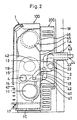
- Fig. 2 is a side elevational view of the gas heater apparatus when installed along a building wall, but partially sectioned;
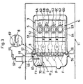
- Fig. 3 is a front view of a burner;
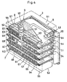
- Fig. 4 is a perspective view of the burner;
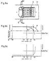
- Fig. 5a is a schematic view of the burner;
- Figs. 5b and 5c are graphical representations to depict characteristic curves of output from a flame rod;
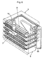
- Fig. 6 is a perspective view of a gas burner which is to be incorporated into the gas heater apparatus according to a second embodiment of the invention;
- Figs. 7a and 7b are graphical representations to depict characteristic curves of output from a thermocoupler according to the second embodiment of the invention;
- Fig. 8 is a block diagram of a safety device which is to be incorporated into the gas heater apparatus according to a third embodiment of the invention;
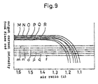
- Fig. 9 is a graphical representation to schematically depict a relationship between a reference value of the safety device and the characteristic curve of the flame rod according to the third embodiment of the invention; and
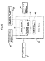
- Fig. 10 is a block diagram of a safety device which is to be incorporated into the gas heater apparatus according to a fourth embodiment of the invention.
-
- Referring to Figs. 1 and 2 which shows a
gas burner apparatus 100 according to a first embodiment of the invention, thegas burner apparatus 100 has a flat-shaped metal casing 1 in which acentrifugal type blower 2 is installed as shown at the right hand side in Fig 1. At a lower section of the metal casing 1, acombustion cylinder 11 is laterally placed. At the right hand side in thecombustion cylinder 11, aburner 3 is provided to which combustion air and gaseous fuel are supplied respectively through an outlet of theblower 2 and afuel supply mechanism 12 so as to carry out combustion by forcibly supplying an outer air. - As shown in Fig. 2, a back plate 1A of the metal casing 1 has a
metal farame 200 to arrange an intake pipe (air duct) to communicate theblower 2 with the outer air, and rooting an exhaust pipe (exhaust duct) to expel an combustion gas out of a room. It is to be noted that the blower may be placed in the exhaust duct to introduce the outer air into the air duct (so-called intake system). - The
blower 2 has an intake cylinder whose inner space serves as aninlet 21. Theinlet 21 pierces the back plate 1A to be in themetal frame 200 so as to be connected to anintake duct 22 which is connected to an outerair intake duct 23 which passes through an opening H provided on a partition wall W. - Above the
combustion cylinder 11, there lies acylindrical heat exchanger 13 laterally within the metal casing 1. A left open end of theheat exchanger 13 is connected to that of thecombustion cylinder 11 by means of anintermediary cylinder 14 which is rectangular in cross section. Between theheat exchanger 13 and thecombustion cylinder 11, anexhaust cylinder 4 is provided in parallel therewith. - A right open end of the
heat exchanger 13 is connected to that of theexhaust cylinder 4 by means of anintermediary cylinder 15 which is rectangular in cross section. As shown at the left hand side in Fig. 1, a leadingend 41 of theexhaust cylinder 4 is angularly bent, and pierced the back plate 1A to form a exhaust opening 40. To the exhaust opening 40, an exhaust duct 44 is connected which has a lateral arm 43 and avertical arm 42. - Concentrically passes through the outer
air intake duct 23 within the opening H is the lateral arm 43 of the exhaust duct 44 whose outer end extends beyond that of theair intake duct 23. At an upper space within the metal casing 1, acentrifugal fan 45 is laterally provided to supply a warm air current. When thefan 45 is activated, it draws an indoor air from aninlet opening 46 provided on an upper portion of the back plate 1A, and sending forth through an outlet opening 47 provided on a lower portion of the back plate 1A. - During the process in which the indoor air is drawn and sent forth via the outlet opening 47, the indoor air is warmed by flowing through the
heat exchanger 13,exhuast cylinder 4 and-thecombustion cylinder 11. On abottom plate 1C of the metal casing 1, anevaporation dish 17 is retractably placed to adjust humidity.Numeral 18 designates a circulation pipe which sends a part of the combustion gas to theblower 2 to operate the burner at rlatively low temperature so as to reduce the emission of NOx-related gas. - The
burner 3, which is placed at the right hand side in thecombustion cylinder 11, has flat-shaped burner units 6 (6A, 6B, 6C, 6D) which are parallel stacked with acertain space 61 interposed therebetween. Thespace 61 acts as a secondary air passage. Theburner units rectangular support frame 5. Between a side wall of theupper burner unit 6A and anupper wall 51 of thesupport frame 5, there is provided aspace 52. Between a lower side wall of thelower burner unit 6D and anlower wall 53 of thesupport frame 5, there is provided aspace 54. These spaces serve as the a secondary air passage. - At the left end side of the
support frame 5,strip plates upper wall 51 andlower wall 53 to be attached in turn to supportplates combustion cylinder 11 in order to support theburner 3 within thecombustion cylinder 11. With each of theburner units 6, an open-endedduct 63 is provided at the upstream of the secondary air passage to introduce gaseous fuel and primary air current. At an elevational side of theburner units 6, a fuelgas supply tube 65 is provided which has fournozzles duct 63. - At a downstream side of the
burner units 6, a multitude of flame slits (flame holes) 66 are provided in four rows with a predetermined clearance interposed therebetween. A secondaryair shield plate 7 is provided at a bottom of theupper burner unit 6A to regulate the secondary air current supplied to the central flame slits 66 of theupper burner unit 6A. Within theupper wall 51 of thesupport frame 5, a secondary airpassage shield plate 8 is provided to partially clog thespace 52. - The secondary
air shield plate 7 is generally formed into L-shaped configuration. Theshield plate 7 has a lateral arm 71 directed along flames F built up on the flame slits 66, and having avertical arm 72 bent in a direction to intersect the flames F. The secondary airpassage shield plate 8 has astrip plate 81 welded to theupper wall 51 of thesupport frame 5, anocculusive plate 82 to clog thespace 52 and anengagement plate 83 which is brought in contact with an upper side wall of theupper burner unit 6A. The secondary airpassage shield plate 8 occulates an entire breadth of thespace 52. Instead of occulating the entire breadth of thespace 52, the secondary airpassage shield plate 8 may be adapted to be the same breadth of the secondaryair shield plate 7, and located vertically in correspondence to the secondaryair shield plate 7. - At the right side of the
combustion cylinder 11, aflame rod 9 is pierced therethrough as a temperature sensor to detect the burning condition of theburner 3. Theflame rod 9 has anelectrode 92 pierced through aninsulator 91. Afront end 93 of theelectrode 92 faces the lateral arm 71 of the secondaryair shield plate 7 so as to be in contact with the flames F. An output generated from theflame rod 9 is to be fed to safety valve to close the safety valve provided in the gaseousfuel supply mechanism 12 when the burning condition deteriorates to lift the flames F. - According to the present invention, the burning condition of the flames F occulated by the
shield plates entire burner 3 when air ratio in theburner unit 6A reduces due to a lenthwise alteration of theexhaust pipe 4 or the outerair intake duct 23. This holds true when theblower 2 loses its sufficient capacity, otherwise theexhaust pipe 4 and the outerair intake duct 23 is clogged by the foreign matters. - In the burner apparatus according to the present invention, the inventors have striven to conform to the requirement that "a furnace shall not produce a concentration of carbon monoxide in excess of 0.04 percent in an air-free sample of the flue gases when tested in an atmosphere having normal oxygen supply." In order to meet the requirement, the inventors have introduced a CO Air-Free concept which is referred to as "COAF" hereinafter.
- Fig. 5a shows a
flame rod 9 provided on theburner 3 in vertical relationship with theflame rod 9 to carry out a comparative experimental test by changing the air ratio (λ) of theburner 3 as a whole. Fig. 5b shows an experimental test result from which it is found that the output (B) of theflame rod 9 is more sensitive against the reduction of the air ratio (λ) than the output (A) of theflame rod 9. - The structure is such that a current intensity (I) of the
flame rod 9 drops to activate the safety valve early before the emission of carbon monoxide increases when an amount of the air supply reduces due to the lengthenedexhaust pipe 4, otherwise due to theexhaust pipe 4 clogged by a piece of snow, bird's nest or spider's cobweb. This is true when theblower 2 loses its sufficient capacity, otherwise when an intake air is short of oxygen by getting the combustion gas back to the inlet opening. - Fig. 5c shows how COAF (CO Air Free Value) changes depending on the air ratio (λ). The output (A) from the prior flame rod 9a drops rapidly when the air ratio (λ) is under 1.0 as shown in Fig. 5b. This is the case that is likely to increase COAF so as to result in an increased emission of carbon monoxide. On the contrary, the output (B) from the
flame rod 9 drops rapidly when the air ratio (λ) is around 1.1, which makes it possible to activate the safety valve before the entire burning condition would have deteriorated. - It is to be noted that COAF in Fig. 5c increases as approching upward along the axis of ordinates while COAF in Fig. 5b decreases as approaching upward along the axis of ordinates.
- It is also to be noted a specified one of the
burner units 6 may be occulated to block an entry of the primary air current as an air reduction means to restrict the air supply toward the specifed flame slits more than that of the other ones of the flame slits 66. - It is further to be observed that the spaces may be partly occulated between the
burner units 6 as a secondary air reduction member. - Alternatively, one of the secondary
air shield plate 7 and the secondary airshield passage plate 8 may be omitted. Theseplates plates - As shown in Fig. 6, a thermocoupler TC may be provided as the temperature sensor instead of the
flame rod 9 according to a second embodiment of the invention. Fig. 7a shows a characteristic curve representative of an electromotive force generated from the thermocoupler TC. Fig. 7b shows how COAF varys depending on the air ratio (λ). - In this instance, as the case of Figs. 5b, 5c, COAF in Fig. 7b increases as approching upward along the axis of ordinates while COAF in Fig. 7a decreases as approaching upward along the axis of ordinates.
- Figs. 8 and 9 show a third embodiment of the invention in which a plurality of reference values are provided as opposed to the first and second embodiment of the invention in which the abnormal combustion is detected on the basis of a single reference value such as the output from the
flame rod 9 or the thermocoupler TC. - The plurality of reference values are represented by the gaseous fuel types to be used, an exhaust mode which changes depending on the air passage length of the
intake duct 22 and exhaust duct 44, and the combustion quantity which theburner 3 produces depending on the temperature adjustment. - By way of illustration, these reference values are represented by Table 1.

- The gaseous fuel types are represented by natural gas and liquefied petroleum gas. In correspondence to the gaseous fuel types, four types of resultant modes are predetermined in order to cope with the air passage of different lengths. One is a direct exhaust mode in which an extension pipe is not connected to the
intake duct 22 and exhaust duct 44. The other is an extension mode in which the extension pipe is connected to theintake duct 22 and exhaust duct 44. In order to cope with the different combustion quantity which theburner 3 produces, the combustion quantity is divided into three sections, i.e., strong, weak and temperature adjustment area in correspondence to each of the modes to designate twelve reference values in total. - It is to be observed that these twelve reference values are not specified in tangible numbers since the reference values can be variously determined depending on the gaseous fuel types and the breadth from minimum to maximum combustion quantity.
- Among the reference values thus predetermined, a group of the reference values are determined in correspondence to each of the gaseous fuel types depending on the combustion quantity. Another group of the reference values are determined in correspondence to each of the gaseous fuel types depending on the intake and exhaust air passage of different lengths. These groups of the reference values are stored by a
storage memory 111 of a microcomputer in asafety device 110 as criterion reference value data. Upon operating thegas heater apparatus 100, one of the reference values is selected among the criterion reference value data to cope with the operating condition by means of a criterion referencevalue selection member 112 which is incorporated into the microcomputer. - The criterion reference
value selection member 112 searches the modes at Table 1 based on a setting signal generated by adip switch 120 for a manufacturer to predetermine the gaseous fuel type to be used, and at the same time, relying on a changing signal generated by an extension pipe determining swich 130 to detect whether or not the extension pipe is connected to an connection end of theintake duct 22 and the exhaust duct 44. Then, the criterion referencevalue selection member 112 selects a single one reference value among the searched modes in correspondence to the combustion quantity on the basis of a control signal generated by acombustion control member 113 of the microcomputer which adjusts the combustion quantity of theburner 3. - In correspondence to each of the searched modes, the
safety device 110 recognizes an output singnal (M∼R in Fig. 9) from theflame rod 9 on the basis of the reference value (m∼r in Fig. 9) selected by the criterion referencevalue selection member 112. When the output singnal of theflame rod 9 reduces to be smaller than the reference value as shown at an intersection of phantom and solid lines in Fig. 9, thesafety device 110 closes the valve to cease the combustion of theburner 3 so as to prevent the abnormal combustion from inadvertently continuing. - It is to be observed that the output signal of the
flame rod 6 is represented by six types of modes in Fig. 9 for the purpose of convenience. The output signal of theflame rod 6 and the reference values at Table 1 are not specified in a tangible number. - As understood from the foregoing description, it is possible to determine whether or not the abnormal combustion occurs in the
burner 3 based on the optimal reference value in correspondence to the combustion quantity depending on the gaseous fuel types and whether or not the extension pipe connection is used. This makes it possible to enlarge a good burning area of the gas burner apparatus of different fuel types and the exhaust modes so as to prevent the combustion from inadvertently ceased whileburner 3 maintains a good burning condition. - Fig. 10 shows a fourth embodiment of the invention in which an extension pipe
connection switch portion 131 is provided instead of the extension pipe determining switch 130. Theswitch portion 131 on-off actuates a switch member on a control circuit base plate by an operator when the extension pipe is connected to the connection end of theintake duct 22 and the exhaust duct 44. - Examples of the
switch portion 131 are as follows: - (1) Pin or pins of a pin terminal placed on the control circuit base plate.
- (2) A circuit alteration by selectively severing lead wires which connect amomg switching portions by means of short circuit.
- (3) An inexpensive dip switch, slide switch and various sorts of switching members.
-
- As shown by the above examples, the
switch portion 131 categorically belongs to those which are difficult to handle upon altering the circuit wiring once programming is set at the time of installing the gas heating apparatus. - It is to be appreciated that in addition to dividing the combustion quantity into three types of the strong, weak and temperature adjustment area which are distinguished by the scale of the flames F, the temperature adjustment area may be further divided minutely to increase accessible reference values to be selected if the
storage memory 111 and the criterion referencevalue selection member 112 have more capacity while giving no significant influence on the programming procedures. - It is also to be noted that the present invention is not only applied to the gas heater apparatus but also applied to a hot water server, water boiler and heater apparatus with a hot water server.
Claims (16)
- A burner apparatus comprising:a burner (3) to which, in use, a gaseous fuel and air are supplied by means of a blower (2);a temperature sensor (9) provided to detect the burning condition of flames built up on at least one specified flame hole; anda safety device activated depending on an output generated from the temperature sensor; characterised by:an air reduction member (7,8) provided to reduce an amount of further air supplied to the specified flame hole(s) of the burner to less than the amount of air supplied to other flame holes.
- An apparatus according to claim 1, wherein the air-reduction member (7,8) is a secondary air reduction member which regulates an amount of secondary air supplied to the specified flame hole of the burner.
- An apparatus according to claim 2, wherein the burner (3) comprises a support frame (5) and a plurality of flat burner units (6A-6D) on which the flame holes (66) are provided, and the flat burner units (6A-6D) are interfit into the support frame (5) to be longitudinally of laterally arranged with their neighbouring spaces (61) as secondary air passages.
- An apparatus according to claim 2 or 3, wherein the secondary air reduction member is a secondary air shield (7) plate provided downstream of the flames built up on the specified flame hole.
- An apparatus according to claim 4, wherein the secondary air shield plate comprises a horizontal portion (71) directed along the flames built up on the specified flame hole, and a vertical portion (72) directed to intersect the flames built up on the specified flame hole.
- An apparatus according to claim 2 or 3, wherein the secondary air reduction member is a secondary air passage shield plate (8) to block the space between the burner units (6A-6D) or between the support frame and the burner units (6A-6D).
- An apparatus according to claims 1 to 6, wherein the temperature sensor is a flame rod (9) or a thermocoupler.
- An apparatus according to any one of claims 1 to 7, wherein the safety device (111) has a plurality of reference values to determine whether to activate or not in response to different outputs generated from the temperature sensor.
- An apparatus according to claim 8, wherein the plurality of reference values correspond to a plurality of combustion quantity values which change depending on the burning condition of the burner, and the safety device determines whether to activate or not by selecting one of the reference values to compare to the combustion quantity value.
- An apparatus according to claim 9, wherein a plurality of combinations among the reference value versus the combustion quantity value are determined, and the safety device (111) selects one of the combinations of the reference value versus the combustion quantity value depending on the burning condition of the burner.
- An apparatus according to claim 8, wherein the plurality of reference values correspond to a plurality of combustion fuel types, and the safety device (111) determines whether to activate or not by selecting one of the reference values to compare to the combustion fuel type.
- An apparatus according to claim 8, 9 or 10, further comprising a mode selection member (120) to select the reference value as combination of the reference value versus the combustion quantity value, and the mode selection member is a manual switch to set a desired mode depending on the combustion fuel type to be used.
- An apparatus according to claim 8, wherein the plurality of reference values correspond to a plurality of air supply and exhaust lengths of the burner and the safety device determines whether to activate or not with reference to a selected one of the reference values.
- An apparatus according to claim 9, wherein a plurality of combinations of the reference value versus the air supply and exhaust length are determined, and the safety device selects one mode among the combinations among the reference value versus the air supply and exhaust length depending on the burning condition of the burner.
- An apparatus according to claim 13 or 14, wherein a mode selection member is provided through which the safety device selects the one of the combinations of the reference value versus the combustion quantity value, and the mode selection member is a connection determining switch (131) mounted on an air supply and exhaust passage connection to automatically set a desired combustion quantity depending on whether or not an air supply and exhaust passage extension member is connected to the air supply and exhaust passage connection to which the air supply and exhaust passage extension is detachably connected.
- An apparatus according to claim 13 or 14, wherein a mode selection member is provided through which the safety device (111) selects one of the combinations of the reference value versus the combustion quantity value, and the mode selection member is a connection switch mounted on an air supply and exhaust passage connection to manually set a desired combustion quantity depending on whether or not an air supply and exhaust extension member is connected to the air supply and exhaust passage connection to which the air supply and exhaust passage extension is detachably connected as required.
Applications Claiming Priority (6)
| Application Number | Priority Date | Filing Date | Title |
|---|---|---|---|
| JP6252096 | 1996-03-19 | ||
| JP62520/96 | 1996-03-19 | ||
| JP6252096 | 1996-03-19 | ||
| JP03092097A JP3193316B2 (en) | 1996-03-19 | 1997-02-14 | Forced supply and exhaust combustion system |
| JP3092097 | 1997-02-14 | ||
| JP30920/97 | 1997-02-14 |
Publications (3)
| Publication Number | Publication Date |
|---|---|
| EP0797050A2 EP0797050A2 (en) | 1997-09-24 |
| EP0797050A3 EP0797050A3 (en) | 1998-10-07 |
| EP0797050B1 true EP0797050B1 (en) | 2002-02-13 |
Family
ID=26369365
Family Applications (1)
| Application Number | Title | Priority Date | Filing Date |
|---|---|---|---|
| EP97301837A Expired - Lifetime EP0797050B1 (en) | 1996-03-19 | 1997-03-19 | Safety device burner |
Country Status (4)
| Country | Link |
|---|---|
| US (1) | US5919035A (en) |
| EP (1) | EP0797050B1 (en) |
| JP (1) | JP3193316B2 (en) |
| KR (1) | KR100247514B1 (en) |
Families Citing this family (23)
| Publication number | Priority date | Publication date | Assignee | Title |
|---|---|---|---|---|
| DE10113468A1 (en) * | 2000-09-05 | 2002-03-14 | Siemens Building Tech Ag | Control device for an air ratio controlled burner |
| US20080028754A1 (en) * | 2003-12-23 | 2008-02-07 | Prasad Tumati | Methods and apparatus for operating an emission abatement assembly |
| US7118613B2 (en) * | 2004-01-13 | 2006-10-10 | Arvin Technologies, Inc. | Method and apparatus for cooling the components of a control unit of an emission abatement assembly |
| US20050150215A1 (en) * | 2004-01-13 | 2005-07-14 | Taylor William Iii | Method and apparatus for operating an airless fuel-fired burner of an emission abatement assembly |
| US7908847B2 (en) * | 2004-01-13 | 2011-03-22 | Emcon Technologies Llc | Method and apparatus for starting up a fuel-fired burner of an emission abatement assembly |
| US7025810B2 (en) * | 2004-01-13 | 2006-04-11 | Arvin Technologies, Inc. | Method and apparatus for shutting down a fuel-fired burner of an emission abatement assembly |
| US7581389B2 (en) * | 2004-01-13 | 2009-09-01 | Emcon Technologies Llc | Method and apparatus for monitoring ash accumulation in a particulate filter of an emission abatement assembly |
| US20050150376A1 (en) * | 2004-01-13 | 2005-07-14 | Crawley Wilbur H. | Method and apparatus for monitoring the components of a control unit of an emission abatement assembly |
| US7685811B2 (en) * | 2004-01-13 | 2010-03-30 | Emcon Technologies Llc | Method and apparatus for controlling a fuel-fired burner of an emission abatement assembly |
| US7243489B2 (en) * | 2004-01-13 | 2007-07-17 | Arvin Technologies, Inc. | Method and apparatus for monitoring engine performance as a function of soot accumulation in a filter |
| US8641411B2 (en) * | 2004-01-13 | 2014-02-04 | Faureua Emissions Control Technologies, USA, LLC | Method and apparatus for directing exhaust gas through a fuel-fired burner of an emission abatement assembly |
| US20050150219A1 (en) * | 2004-01-13 | 2005-07-14 | Crawley Wilbur H. | Method and apparatus for controlling the temperature of a fuel-fired burner of an emission abatement assembly |
| US20050150216A1 (en) * | 2004-01-13 | 2005-07-14 | Crawley Wilbur H. | Method and apparatus for cleaning the electrodes of a fuel-fired burner of an emission abatement assembly |
| US7628011B2 (en) * | 2004-01-13 | 2009-12-08 | Emcon Technologies Llc | Emission abatement assembly and method of operating the same |
| US8789363B2 (en) | 2007-06-13 | 2014-07-29 | Faurecia Emissions Control Technologies, Usa, Llc | Emission abatement assembly having a mixing baffle and associated method |
| WO2009062281A1 (en) | 2007-11-16 | 2009-05-22 | Wolfedale Engineering Limited | Temperature control apparatus for a barbeque grill |
| US20090180937A1 (en) * | 2008-01-15 | 2009-07-16 | Nohl John P | Apparatus for Directing Exhaust Flow through a Fuel-Fired Burner of an Emission Abatement Assembly |
| US20090178395A1 (en) * | 2008-01-15 | 2009-07-16 | Huffmeyer Christopher R | Method and Apparatus for Regenerating a Particulate Filter of an Emission Abatement Assembly |
| US20090178391A1 (en) * | 2008-01-15 | 2009-07-16 | Parrish Tony R | Method and apparatus for operating an emission abatement assembly |
| US20090178389A1 (en) * | 2008-01-15 | 2009-07-16 | Crane Jr Samuel N | Method and Apparatus for Controlling a Fuel-Fired Burner of an Emission Abatement Assembly |
| JP2011252671A (en) * | 2010-06-03 | 2011-12-15 | Rinnai Corp | Combustion apparatus |
| JP6057780B2 (en) * | 2013-03-01 | 2017-01-11 | サンポット株式会社 | Combustion device |
| JP2020051637A (en) * | 2018-09-25 | 2020-04-02 | 株式会社ノーリツ | Combustion device and water heating device |
Family Cites Families (8)
| Publication number | Priority date | Publication date | Assignee | Title |
|---|---|---|---|---|
| US3295585A (en) * | 1965-07-12 | 1967-01-03 | American Gas Ass | Apparatus for sensing the composition of gases, and gas burner system employing same |
| FR1563239A (en) * | 1968-02-26 | 1969-04-11 | ||
| FR2226059A6 (en) * | 1973-04-16 | 1974-11-08 | Applic Catalytiq Lyonnaise | |
| US4315729A (en) * | 1978-03-02 | 1982-02-16 | Matsushita Electric Industrial Co., Ltd. | Gas burner |
| US4221557A (en) * | 1978-06-12 | 1980-09-09 | Gas Research Institute | Apparatus for detecting the occurrence of inadequate levels of combustion air at a flame |
| US4358265A (en) * | 1979-06-15 | 1982-11-09 | Matsushita Electric Industrial Co., Ltd. | Combustion appliance with a safety device |
| DE2950689A1 (en) * | 1979-12-17 | 1981-06-25 | Servo-Instrument, in Deutschland Alleinvertrieb der BEAB-Regulatoren GmbH u. Co KG, 4050 Mönchengladbach | CONTROL DEVICE FOR THE COMBUSTION AIR AMOUNT OF A FIREPLACE |
| DE69320514T2 (en) * | 1992-03-26 | 1999-04-29 | Matsushita Electric Industrial Co., Ltd., Kadoma, Osaka | Gas appliance |
-
1997
- 1997-02-14 JP JP03092097A patent/JP3193316B2/en not_active Expired - Lifetime
- 1997-03-18 KR KR1019970009066A patent/KR100247514B1/en not_active Expired - Fee Related
- 1997-03-19 EP EP97301837A patent/EP0797050B1/en not_active Expired - Lifetime
- 1997-03-19 US US08/825,698 patent/US5919035A/en not_active Expired - Lifetime
Also Published As
| Publication number | Publication date |
|---|---|
| KR19980069717A (en) | 1998-10-26 |
| US5919035A (en) | 1999-07-06 |
| KR100247514B1 (en) | 2000-04-01 |
| JPH09310850A (en) | 1997-12-02 |
| EP0797050A3 (en) | 1998-10-07 |
| JP3193316B2 (en) | 2001-07-30 |
| EP0797050A2 (en) | 1997-09-24 |
Similar Documents
| Publication | Publication Date | Title |
|---|---|---|
| US5919035A (en) | Cross flow type burner apparatus | |
| US6595199B1 (en) | Stove for solid fuel | |
| US4766883A (en) | Forced draft controlled mixture heating system using a closed combustion chamber | |
| US4221557A (en) | Apparatus for detecting the occurrence of inadequate levels of combustion air at a flame | |
| US20020160326A1 (en) | Gas pilot system and method having improved oxygen level detection capability and gas fueled device including the same | |
| NZ247183A (en) | Forced draught, fuel fired water heater; downwardly directed top mounted burner with turnbowl and vent tubes at bottom | |
| US20070287111A1 (en) | Variable input radiant heater | |
| US20080118877A1 (en) | System and Control Method of Oil Burner's Suitable Burning Ratio Using Air Pressure Sensor | |
| CA2166743C (en) | Wall heater with improved heat exchanger | |
| CA2099227C (en) | Standing pilot furnace with vented vestibule | |
| US5338184A (en) | Gas burner system, gas burner and a method for combustion control | |
| JP2003042444A (en) | Water heater | |
| JP3373936B2 (en) | Combustion equipment | |
| JPH09217929A (en) | Combustion apparatus | |
| JPS5852913A (en) | Combustion safety apparatus | |
| US12098867B1 (en) | Water heating system and method of operating the same | |
| JP3498544B2 (en) | Far-infrared radiation hot air heater | |
| JP3468940B2 (en) | Gas combustion equipment | |
| JP3708145B2 (en) | Burner equipment | |
| JP6675920B2 (en) | Hybrid gas fan heater | |
| JP2537782B2 (en) | Combustion device | |
| JP3087200B2 (en) | Combustion safety device | |
| JP3639337B2 (en) | Combustion device and control device therefor | |
| JPS58224248A (en) | combustion appliances | |
| EP0291584A1 (en) | Heating apparatus comprising a burner of the kind to which a substantially stoechiometric fuel/airmixture is supplied |
Legal Events
| Date | Code | Title | Description |
|---|---|---|---|
| PUAI | Public reference made under article 153(3) epc to a published international application that has entered the european phase |
Free format text: ORIGINAL CODE: 0009012 |
|
| AK | Designated contracting states |
Kind code of ref document: A2 Designated state(s): BE FR GB IT NL |
|
| PUAL | Search report despatched |
Free format text: ORIGINAL CODE: 0009013 |
|
| AK | Designated contracting states |
Kind code of ref document: A3 Designated state(s): BE FR GB IT NL |
|
| 17P | Request for examination filed |
Effective date: 19981202 |
|
| 17Q | First examination report despatched |
Effective date: 20000724 |
|
| GRAG | Despatch of communication of intention to grant |
Free format text: ORIGINAL CODE: EPIDOS AGRA |
|
| RTI1 | Title (correction) |
Free format text: SAFETY DEVICE BURNER |
|
| GRAG | Despatch of communication of intention to grant |
Free format text: ORIGINAL CODE: EPIDOS AGRA |
|
| GRAH | Despatch of communication of intention to grant a patent |
Free format text: ORIGINAL CODE: EPIDOS IGRA |
|
| GRAH | Despatch of communication of intention to grant a patent |
Free format text: ORIGINAL CODE: EPIDOS IGRA |
|
| GRAA | (expected) grant |
Free format text: ORIGINAL CODE: 0009210 |
|
| REG | Reference to a national code |
Ref country code: GB Ref legal event code: IF02 |
|
| AK | Designated contracting states |
Kind code of ref document: B1 Designated state(s): BE FR GB IT NL |
|
| ET | Fr: translation filed | ||
| PLBE | No opposition filed within time limit |
Free format text: ORIGINAL CODE: 0009261 |
|
| STAA | Information on the status of an ep patent application or granted ep patent |
Free format text: STATUS: NO OPPOSITION FILED WITHIN TIME LIMIT |
|
| 26N | No opposition filed |
Effective date: 20021114 |
|
| PGFP | Annual fee paid to national office [announced via postgrant information from national office to epo] |
Ref country code: FR Payment date: 20100324 Year of fee payment: 14 |
|
| PGFP | Annual fee paid to national office [announced via postgrant information from national office to epo] |
Ref country code: NL Payment date: 20100304 Year of fee payment: 14 |
|
| REG | Reference to a national code |
Ref country code: NL Ref legal event code: V1 Effective date: 20111001 |
|
| REG | Reference to a national code |
Ref country code: FR Ref legal event code: ST Effective date: 20111130 |
|
| PG25 | Lapsed in a contracting state [announced via postgrant information from national office to epo] |
Ref country code: NL Free format text: LAPSE BECAUSE OF NON-PAYMENT OF DUE FEES Effective date: 20111001 Ref country code: FR Free format text: LAPSE BECAUSE OF NON-PAYMENT OF DUE FEES Effective date: 20110331 |
|
| PGFP | Annual fee paid to national office [announced via postgrant information from national office to epo] |
Ref country code: IT Payment date: 20140319 Year of fee payment: 18 |
|
| PGFP | Annual fee paid to national office [announced via postgrant information from national office to epo] |
Ref country code: GB Payment date: 20140319 Year of fee payment: 18 |
|
| PGFP | Annual fee paid to national office [announced via postgrant information from national office to epo] |
Ref country code: BE Payment date: 20140312 Year of fee payment: 18 |
|
| GBPC | Gb: european patent ceased through non-payment of renewal fee |
Effective date: 20150319 |
|
| PG25 | Lapsed in a contracting state [announced via postgrant information from national office to epo] |
Ref country code: IT Free format text: LAPSE BECAUSE OF NON-PAYMENT OF DUE FEES Effective date: 20150319 |
|
| PG25 | Lapsed in a contracting state [announced via postgrant information from national office to epo] |
Ref country code: GB Free format text: LAPSE BECAUSE OF NON-PAYMENT OF DUE FEES Effective date: 20150319 |
|
| PG25 | Lapsed in a contracting state [announced via postgrant information from national office to epo] |
Ref country code: BE Free format text: LAPSE BECAUSE OF NON-PAYMENT OF DUE FEES Effective date: 20150331 |