EP0796599A2 - Verriegelungsvorrichtung zum Kuppeln und Verriegeln einer Rollstuhlkomponente zum Rollstuhlrahmen sowie ein Rollstuhl - Google Patents
Verriegelungsvorrichtung zum Kuppeln und Verriegeln einer Rollstuhlkomponente zum Rollstuhlrahmen sowie ein Rollstuhl Download PDFInfo
- Publication number
- EP0796599A2 EP0796599A2 EP97610005A EP97610005A EP0796599A2 EP 0796599 A2 EP0796599 A2 EP 0796599A2 EP 97610005 A EP97610005 A EP 97610005A EP 97610005 A EP97610005 A EP 97610005A EP 0796599 A2 EP0796599 A2 EP 0796599A2
- Authority
- EP
- European Patent Office
- Prior art keywords
- wheel chair
- locking
- component
- chair frame
- fitting
- Prior art date
- Legal status (The legal status is an assumption and is not a legal conclusion. Google has not performed a legal analysis and makes no representation as to the accuracy of the status listed.)
- Granted
Links
Images


Classifications
-
- A—HUMAN NECESSITIES
- A61—MEDICAL OR VETERINARY SCIENCE; HYGIENE
- A61G—TRANSPORT, PERSONAL CONVEYANCES, OR ACCOMMODATION SPECIALLY ADAPTED FOR PATIENTS OR DISABLED PERSONS; OPERATING TABLES OR CHAIRS; CHAIRS FOR DENTISTRY; FUNERAL DEVICES
- A61G5/00—Chairs or personal conveyances specially adapted for patients or disabled persons, e.g. wheelchairs
- A61G5/10—Parts, details or accessories
- A61G5/12—Rests specially adapted therefor, e.g. for the head or the feet
-
- A—HUMAN NECESSITIES
- A61—MEDICAL OR VETERINARY SCIENCE; HYGIENE
- A61G—TRANSPORT, PERSONAL CONVEYANCES, OR ACCOMMODATION SPECIALLY ADAPTED FOR PATIENTS OR DISABLED PERSONS; OPERATING TABLES OR CHAIRS; CHAIRS FOR DENTISTRY; FUNERAL DEVICES
- A61G5/00—Chairs or personal conveyances specially adapted for patients or disabled persons, e.g. wheelchairs
- A61G5/10—Parts, details or accessories
- A61G5/1054—Large wheels, e.g. higher than the seat portion
-
- A—HUMAN NECESSITIES
- A61—MEDICAL OR VETERINARY SCIENCE; HYGIENE
- A61G—TRANSPORT, PERSONAL CONVEYANCES, OR ACCOMMODATION SPECIALLY ADAPTED FOR PATIENTS OR DISABLED PERSONS; OPERATING TABLES OR CHAIRS; CHAIRS FOR DENTISTRY; FUNERAL DEVICES
- A61G5/00—Chairs or personal conveyances specially adapted for patients or disabled persons, e.g. wheelchairs
- A61G5/10—Parts, details or accessories
- A61G5/12—Rests specially adapted therefor, e.g. for the head or the feet
- A61G5/125—Rests specially adapted therefor, e.g. for the head or the feet for arms
-
- A—HUMAN NECESSITIES
- A61—MEDICAL OR VETERINARY SCIENCE; HYGIENE
- A61G—TRANSPORT, PERSONAL CONVEYANCES, OR ACCOMMODATION SPECIALLY ADAPTED FOR PATIENTS OR DISABLED PERSONS; OPERATING TABLES OR CHAIRS; CHAIRS FOR DENTISTRY; FUNERAL DEVICES
- A61G5/00—Chairs or personal conveyances specially adapted for patients or disabled persons, e.g. wheelchairs
- A61G5/10—Parts, details or accessories
- A61G5/12—Rests specially adapted therefor, e.g. for the head or the feet
- A61G5/128—Rests specially adapted therefor, e.g. for the head or the feet for feet
Definitions
- the present invention relates generally to wheel chairs and more particularly to structures or a locking fitting for coupling and locking a wheel chair component such as a leg support, an arm rest or a back rest to a frame of a wheel chair, the locking fitting having coupling means adapted to couple the wheel chair component to the wheel chair frame in such a manner that the wheel chair component may pivot to an angle relative to the wheel chair frame around a pivoting axis defined by the wheel chair frame, as well as locking means being switchable between a first position wherein the wheel chair component is locked to the wheel chair frame and a second position wherein the wheel chair component is pivotable with respect to the wheel chair frame around said pivoting axis.
- a wheel chair component such as a leg support, an arm rest or a back rest to a frame of a wheel chair
- the locking fitting having coupling means adapted to couple the wheel chair component to the wheel chair frame in such a manner that the wheel chair component may pivot to an angle relative to the wheel chair frame around a pivoting axis defined by the wheel chair frame,
- a structure of this type is in this context designated a locking fitting and is to be considered as a generic term comprising not only separate fittings but also structural elements that may comprise one, two or more separate parts that can be coupled together to provide the said coupling or locking of a wheel chair component to a wheel chair frame.
- a special application of the locking fitting according to the present invention is coupling or locking a leg support to the wheel chair frame.
- the prior art locking fittings for use in connection with the coupling or locking of in particular leg supports to wheel chair frames only allow the leg support to swing to one of the sides which to a large extent limits the usefulness of not alone the leg support but of the entire wheel chair.
- An example of such a prior art locking fitting is shown and described in US Patent No. 4,770,467 describing a leg support for a wheel chair.
- the leg support comprises a pivoting arm journalled pivotably with respect to the wheel chair frame, a foot support plate being mounted in the outer free end of said arm.
- the leg support In the normal operative position, the leg support is locked to the wheel chair frame and projects forwards from the wheel chair frame in such a manner that the person or patient sitting in the wheel chair may rest his or her feet on said plate of the leg support.
- the leg support may as described above, e.g. when the user is to sit at a table or be moved from the wheel chair to or from a bed, be swung away and out to one side so that it is possible to guide the wheel chair in under a table or bed as described above.
- leg support structure does not allow swinging the leg support in under the wheel chair frame and therefore, operative situations arise where the leg supports and other corresponding wheel chair components of a wheel chair that only may be swung to one side with respect to a normal operative position necessarily will be in the way for either the user or any assistant independent of whether the leg support or the corresponding wheel chair component is locked in the normal operative position or has been swung to the side.
- this object is achieved with a locking fitting for coupling or locking a wheel chair component, particularly a leg support for a wheel chair frame
- the locking fitting according to the invention being characterized in that the locking fitting is provided with coupling means adapted to couple the wheel chair component to the wheel chair frame in such a way that the wheel chair component can pivot to an angle with respect to the wheel chair frame around a pivoting axis defined by the wheel chair frame, and locking means being switchable between a first position wherein the wheel chair component is locked to the wheel chair frame and a second position wherein the wheel chair component is pivotable with respect to the wheel chair frame around said pivoting axis, and that the first position corresponds to a specific angular position of the wheel chair component with respect to the wheel chair frame, the wheel chair component being able to pivot from said angular position to one or the other side when the locking means have been switched to the second position.
- the locking fitting according to the invention is, however, not only for use in connection with coupling and locking a leg support to a wheel chair frame but may furthermore e.g. be used for coupling or locking an arm rest, a back rest or some other component of a wheel chair relative to the wheel chair frame.
- the locking fitting according to the invention may furthermore be modified such that the fitting not only exhibits one single locking position but two or more locking positions corresponding to e.g. locking a back rest in two or more positions relative to the seat of the wheel chair.
- a wheel chair component such as a leg support should not only because of functional reasons be able to swing from one side to another in relation to the locking position but it should also advantageously be able to be dismantled or removed from the wheel chair frame to allow that the wheel chair component, when the wheel chair is constructed with a collapsible and transport-abel wheel chair frame, may be dismantled or removed from the wheel chair frame.
- the locking means are therefore adapted to allow that the wheel chair component, particularly the leg support, may be removed from the wheel chair frame when the wheel chair component has been swung to one of the sides from said angular position.
- the wheel chair component may accordingly not be removed from the wheel chair frame when only the locking fitting has been switched over to the other position but it can only be removed from the wheel chair frame when the wheel chair component has been swung to said one of the sides from said angular position corresponding to the first position or locking position of the locking means.
- the locking fitting is adapted to only allow that the wheel chair component, particularly the leg support, may be removed from the wheel chair frame when the wheel chair component has been swung to one of the sides while the wheel chair component, particularly the leg support, cannot be removed from the wheel chair frame when the wheel chair component has been swung to the other position from said angular position.
- the locking means are adapted to allow that the wheel chair component, particularly the leg support, may be removed from the wheel chair frame when the wheel chair component has been swung to one or the other side from said angular position.
- the wheel chair component, particularly the leg support may thus be removed from the wheel chair frame if only the wheel component has been swung to one or the other side from said angular position wherein removal of the wheel chair component is prevented by the locking means.
- the locking fitting according to the present invention particularly advantageously constitutes a locking fitting for coupling and locking a leg support to a wheel chair frame
- the locking fitting according to the present invention may thus, as explained above, constitute one single component or a structure comprising several components cooperating to couple or lock the leg support with respect to the wheel chair frame.
- the locking fitting is adapted to couple and lock a leg support to a vertical support tube of a wheel chair frame.
- the locking fitting comprises a plate shaped component fixedly connected to the leg support and defining a cylinder surface constituting said coupling means and adapted to abut an outer surface of the support tube when the leg support is mounted on the wheel chair frame, the locking means comprising a locking pin fixedly connected to the support tube and arranged at a peripheral distance from said outer surface of the support tube, as well as at least two locking pawls supported by said plate shaped component and adapted to, in the first position of the locking means, project forwards from an edge of said plate shaped component and at least partly grip around said locking pin as well as being adapted to, in the second position of the locking means, be move back behind said edge of the plate shaped component so as to release the locking pawls from the engagement with the locking pin.
- the locking fitting according to the present invention is preferably provided with an operating means which according to alternative embodiments may be constituted by a push button, a twirling knob, a thumb screw, etc.
- the operating means is constituted by a handle allowing operation of the locking fitting and switching of the locking means from the first to the second position even for users that are physically weak and accordingly would have difficulties in exerting a pressure necessary to activate e.g. a push button, the locking pawls being movable by means of a handle between the position projecting forwards from the edge of the plate shaped component and said retracted position corresponding to the first position and second position, respectively, of the locking means.
- the currently preferred embodiment of the locking fitting according to the present invention is furthermore preferably provided with a locking knob adapted to engage in a locking incision in the locking pin in said first position of the locking means.
- the locking fitting according to the present invention preferably comprises a locking knob located between the locking pawls and displayed with respect to the locking pawls when viewed in the axial direction of the locking pin.
- a second aspect of the present invention concerns a wheel chair with a wheel chair frame, two wheels connected to the wheel chair frame, a seat as well as a wheel chair component such as a leg support, an arm rest or a back rest, being pivotably mounted on the wheel chair frame and lockable with respect to same, the wheel chair frame having a locking fitting for coupling and locking the wheel chair component to the wheel chair frame, the locking fitting having coupling means adapted to couple the wheel chair component to the wheel chair frame in such a way that the wheel chair component may pivot at an angle relative to the wheel chair frame around a pivoting axis defined by the wheel chair frame, as well as locking means that may be switched between a first position wherein the wheel chair component is locked to the wheel chair frame and a second position in which the wheel chair component is pivotable with respect to the wheel chair frame around said pivoting axis, the wheel chair according to the invention being characterized in that the first position corresponds to a specific angular position of the wheel chair component with respect to the wheel chair frame, the wheel chair component being able to
- the locking fitting in the wheel chair according to the second aspect of the present invention may exhibit any of the in the foregoing described characterizing features of the locking fitting according to the first aspect of the present invention.
- Fig. 5 shows a wheel chair generally indicated by the reference number 10.
- the wheel chair 10 has a support frame 12 being a per se known collapsible frame supporting a seat 14, a back rest 16 wherefrom two handles 18 and 20 extend rearwards, the handles being for use by an assistant or a nurse to push the wheel chair 10 and a person or patient sitting in same, two arm rests 22 and 24, two wheels 26 and 28, two bracing wheels 30 and 32 as well as two leg supports 34 and 36 being mounted on the frame 12 by means of locking fittings 38 and 40, respectively, constructed in accordance with the teaching of the invention and being mutually inversely symmetrical.
- the locking fitting 40 will be explained more in detail in the following with reference to Figs.
- the locking fitting 38 is constructed in a like manner but being inversely symmetrical with respect to the locking fitting 40.
- the same locking fitting e.g. the locking fitting 40
- the locking fitting may be used in the wheel chair for mounting the leg supports 34 and 36 with respect to the frame 12, but it is preferable from an operational point of view and for ease of use that the locking fittings be inversely symmetrical.
- the locking fitting constructed according to the teaching of the invention alternatively may be used for pivotable but lockable fastening of e.g.
- pivotable arm rests corresponding to the arm rests 22 and 24 in such a manner that the arm rests can be pivoted forwards and rearwards with respect to a locked central position or alternatively may be used for fastening and locking a back rest such as back rest 16 shown in Fig. 4 when the back rest is mounted pivotable with respect to the seat 14, or rather with respect to the frame 12.
- the locking fitting according to the invention may alternatively be used in other connections with relation to wheel chairs where a pivotable conponent is used that must be able to be locked relative to the frame of the wheel chair or some other component of the wheel chair but which in certain circumstances should be able to turn to one or the other side with respect to the locked position and perhaps be released in this or those positions and perhaps be dismantled or removed from the wheel chair.
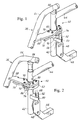
- Fig. 1 shows the locking fitting 40 by means of which the leg support 36 is coupled to the wheel chair frame shown in Fig. 1 as comprising a vertical tube 42 and a horizontal tube 44 on which the seat 14 is arranged.
- the tubes 42 and 44 are fixedly connected to each other and to the tube 42 and furthermore fastened, on one hand to a square section tube 46 connected to the tube 42 by means of a plate shaped component 48, and, on the other hand to a horizontally outwards projecting plate 50 on which an upwards projecting pin 52 is fastened, the pin cooperating with the locking fitting 40 as will be explained below.
- the leg support 36 shown in Fig. 5 and correspondingly, the leg support 34 also shown in Fig. 5 comprise a bent tube 54 defining an upper horizontal length to which is fastened a coupling component constituted by a plastic body 56 fitting into the hollow vertical tube 42 of the wheel chair frame 12.
- the bent tube 54 of the leg support 36 extends from the horizontal length mentioned above obliquely downwards to form an angle of typically 60° or 70°, the bent tube 54 being at its lower end coupled to a tube or a rod 35 being internally displaceable with respect to the tube 54 and at its outer free end being connected to a foot rest 37.
- a plate shaped component or connecting plate 58 extends from the tube 54, the locking fitting being fastened on said plate.
- the plate shaped component 58 provided with a semi circular incision 60 allowing the plate shaped component 58 to partially grip around the vertical tube 52 of the wheel chair frame 12 and at the same time allowing the plate formed component 58 to, on one hand pivot around the tube 42 and, on the other hand be uncoupled from the tube 42.
- Block 62 is fixedly bolted on the underside of the plate shaped component 58 and defines part of an inner surface 64 of a cylinder being adapted to abut against and slide against the outer surface of the tube 42.
- the block 62 is furthermore provided with an outwardly projecting pin shaped portion 66 which, in the locked position of the locking fitting 40 shown in Fig. 1 is adapted to engage in an incision 68 in the pin 52 and prevent the block 62 and thereby the leg support 36 fastened to the block 62 by means of the plate shaped component 58 from being lifted or lowered for release of the leg support from the wheel chair frame e.g. as shown in Fig. 2.
- the block 62 is fastened to the plate shaped component 58 by means of a number of bolts, one of which being indicated by the reference number 17, and two locking pawls 72 and 74 are supported in the block 62 and will he described more in detail below with reference to Fig.
- a handle 75 is provided to uncouple the locking pawls 72 and 74 from the locking relationship with respect to the head of the pin 58, the handle 75 cooperating with the locking pawls 72 and 64 in a coupling which will be described below with reference to Fig. 3.
- the locking fitting 40 shown in Fig. 1 and 2 allows the leg support 36 to be locked in the position shown in Fig. 1 with respect to the tube 42 and thereby the wheel chair frame 12, the portion 66 projecting from the block 62 engaging in the recess 61 in the pin 52 and thereby preventing the block 62 and the entire leg support 36 from moving upwards or downwards with respect to the pin 52 and thereby the wheel chair frame 12.
- the locking pawls 72 and 74 engage in a locking relationship as described above around the head of the pin 52 and thereby prevent pivoting of the plate shaped component 58 and thereby the leg support 36 around a vertical axis with respect to the vertical tube 42 of the wheel chair 12.
- the structure has the advantage that it. on one hand is very stable and, on the other hand is able to resist even extremely large forces, as the locking relationship between the leg support 36 and the wheel chair frame is brought about by means of the plate shaped component 58 that, in connection with the forces exerted in the locking fitting in use, functions as an edgewise placed plate shaped component which furthermore in relation to the structure affords the advantage that the moment to the taken up by the mutually locking portions, i.e.
- the structure thus constitutes, when viewed from above, a triangular structure in which the centre of rotation of the leg support is located at one side of the triangle, the apex of which is connected to the tube 54, the locking relationship between, on one hand the projecting portion 66 of the block 62 and the incision 68 in the pin 52 and, on the other hand the engagement of the locking pawls 72 and 74 with the locking pin 52 is located in the apex of the triangle opposite the centre of rotation mentioned above.
- the locking fitting 40 may be released from the locking position shown in Fig. 1 by activating the handle 75, whereby the locking pawls 72 and 74 are moved in under the plate shaped component 58 as described below with reference to Figs. 3 and 4, whereafter the leg support 36 can be pivoted to one or the other side with relation to the position shown in Fig. 1 whereby the projecting portion 66 of the block 62 is released from engagement in the incision 68 in the pin 52. Thereafter the leg support 36 may furthermore as shown in Fig. 2 be disengaged from the wheel chair frame 12, the body 56 being extracted from the tube 52.
- leg support 36 being fastened only to the wheel chair frame 12 by means of the body 56 may be pivoted freely towards an outermost position either outwards towards the the wheel 28 or alternatively in under the seat 14, the locking fitting 14 when the position shown in Fig. 1 is passed, again locking the leg support 36 with respect to the wheel chair frame 12.
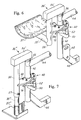
- Fig. 3 is a detailed view of the construction of the locking fitting 40 shown disassembled or exploded.
- Fig. 3 thus shows the coupling between the locking pawls 72 and 74 being influenced towards the positions shown in Fig. 1 and 2 by means of two springs 76 and 78, respectively, that force the locking pawls 72 and 74 outwards from the location inserted in and hidden under the plate shaped component 58.
- the springs 76 and 78 are received in corresponding recesses or milled indentations in the block 62 provided as shown in Fig. 3 with through going bores arranged aligned with the bores in the plate shaped component 58 and wherein the assembly screws are fitted.
- Fig. 3 is a detailed view of the construction of the locking fitting 40 shown disassembled or exploded.
- Fig. 3 thus shows the coupling between the locking pawls 72 and 74 being influenced towards the positions shown in Fig. 1 and 2 by means of two springs 76 and 78, respectively,
- the reference number 82 indicates a hole or a boring in the plate shaped component 58, the bolt 78 being fitted in said hole.
- the reference number 84 indicates a milled indentation wherein the handle 75 is fitted and extends downwards to engage in a hole 80 in the locking pawl 74.
- Fig. 4a shows a horizontal section through the locking fitting 40 mounted on the tube 42. The locking fitting is in the locked position shown in Fig. 1, in which position the projecting portion 66 of the block 62 engages in the milled indentation or incision 68 in the pin 52 while the locking pawls 72 and 74 being biased by the springs 76 and 78 grip around the head of the pin 52.
- the locking pawl 74 By activating the handle 75 in the direction indicated by an arrow in Fig. 4 the locking pawl 74 is forced inwards against the biasing of the spring 78 and at the same time by abutting against a projecting knob 73 on the locking pawl 72 carries this locking pawl along inwards to the position shown in Fig. 4b in which the locking pawls 72 and 74 have been moved in under a plate shaped component 52 and thus are uncoupled from the locking engagement with the head on the pin 52. Thereafter, the leg support 36 coupled to the plate shaped component 38 may freely pivot as shown in Fig. 2 and Fig. 4b.
- Fig. 6 shows an alternative design of a leg support which the locking fitting 40 according to the present invention.
- the leg support shown in Fig. 6 is generally indicated by means of the reference number 36' and constitutes a leg support intended for use by amputation patients.
- the leg support comprises a horizontal block or a beam 54' on which the body 56 is being mounted in much the same way as the body 56 is mounted on the bent tube 54 in the leg support 36 shown in Figs. 1 and 2.
- the block 54' is connected to a vertical tube 55 that, in the position shown in Fig. 6 in which the leg support 36' is fastened to the wheel chair frame 12, extends parallel to the tube 42.
- a tube 35' extends from the tube 55 horizontally inwards with respect to the wheel chair frame and supports a bowl shaped leg support plate 37'.
- the horizontal tube 35' may possibly be connected to the vertical tube 55 by means of a coupling allowing vertical adjustment of the leg support 37' with respect to the tube 55 and thus with respect to the seat 14 of the wheel chair.
- Fig. 7 shows an alternative constructions of a leg support intended for use by children.
- the leg support shown in Fig. 7 is generally indicated by means of the reference number 36" and comprises the components 54' and 55 described above and shown in Fig. 6.
- An inner tube 35" is fastened to the lower end of the tube 55 and is able to be displaced internally in the tube 55 and be locked with respect to same by means of a locking screw 57.
- the tube 35" is connected to a foot plate 37".
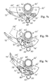
- Fig. 8 shows an alternative embodiment of the locking fitting according to the present invention.
- Fig. 8 and 9a-9c the same reference numbers are used for components corresponding to components described above with reference to Figs. 1-7, the components shown in Figs. 8 and 9a-9c being, however, indicated by the reference '.
- the individual components or elements of the locking fitting 40' shown in Fig. 8 will thus not be described, but the structural and functional differences between the locking fitting 40' shown in Fig. 8 and the locking fitting 40 described above will be explained.
- the locking fitting 40 explained above is adapted to allow the locking fitting to be uncoupled from the normal locked position by pressing the handle 75 towards the connecting plate 58.
- the alternative embodiment of the locking fitting 40' according to the present invention shown in Fig. 8 is adapted to allow the locking fitting to be uncoupled from the normal locking position by moving the handle 75' in a direction either inwards towards the plate shaped component 58' or outwards from the plate shaped component 58' as shown in Fig. 9c and Fig. 9b, respectively.
- the locking fitting shown in Fig. 8 differs generally speaking from the locking fitting described above in that the handle 75' is arranged pivotable with relation to the block 52' by means of a bolt 71' to allow the handle 75' to swing both ways with respect to the normal position shown in Fig.
- Fig. 9a shows the position in which the locking pawls 72' and 74' lock around the pin 52 and lock the leg support to the corresponding wheel chair in the given locked position.
- Fig. 9b and 9c show two alternative release positions for the locking fitting 40', the handle 75' in Fig. 9b being moved forwards or outwards with respect to the plate shaped component 58, the locking pawls 72' and 74' moved by the two guiding pins 73' being pressed inwards from the engagement around the pin 52 whereafter the leg support can pivot to one or the other side with respect to the wheel chair frame.
- Fig. 9c correspondingly shows the position of the handle 75 in which the handle has been moved inwards towards the plate shaped component 58 corresponding to the position shown in Fig. 4b in which the locking pawls 72' and 74', just as in Fig. 9b, are uncoupled from engagement and locking with respect to the pin 52.
- the projecting portion 66 of the block 62 being designed such that the projecting portion extends along a substantial peripheral portion of the block 62 and thus, by swinging the leg support 66 to one side wherein the projecting portion designed with a larger peripheral extent, engages in the incision 68 in the pin 52 and thereby prevents the removal described above of the leg support 66 from the wheel chair frame 12.
- the leg support may be designed in any per se known manner just as the locking fitting as mentioned above may be utilized for other applications in connection with a wheel chair.
Landscapes
- Health & Medical Sciences (AREA)
- Life Sciences & Earth Sciences (AREA)
- Animal Behavior & Ethology (AREA)
- General Health & Medical Sciences (AREA)
- Public Health (AREA)
- Veterinary Medicine (AREA)
- Chairs For Special Purposes, Such As Reclining Chairs (AREA)
- Seats For Vehicles (AREA)
- Handcart (AREA)
- Fittings On The Vehicle Exterior For Carrying Loads, And Devices For Holding Or Mounting Articles (AREA)
- Chair Legs, Seat Parts, And Backrests (AREA)
Applications Claiming Priority (3)
| Application Number | Priority Date | Filing Date | Title |
|---|---|---|---|
| DK9696 | 1996-03-18 | ||
| DK96/96 | 1996-03-18 | ||
| DK9600096U DK9600096U3 (da) | 1996-03-18 | 1996-03-18 | Låsebeslag til sammenkobling af og låsning af en kørestolskomponent til et kørestolsstel samt kørestol |
Publications (3)
| Publication Number | Publication Date |
|---|---|
| EP0796599A2 true EP0796599A2 (de) | 1997-09-24 |
| EP0796599A3 EP0796599A3 (de) | 1998-04-08 |
| EP0796599B1 EP0796599B1 (de) | 2003-07-23 |
Family
ID=8155558
Family Applications (1)
| Application Number | Title | Priority Date | Filing Date |
|---|---|---|---|
| EP97610005A Expired - Lifetime EP0796599B1 (de) | 1996-03-18 | 1997-03-18 | Verriegelungsvorrichtung zum Kuppeln und Verriegeln einer Rollstuhlkomponente zum Rollstuhlrahmen sowie ein Rollstuhl |
Country Status (4)
| Country | Link |
|---|---|
| EP (1) | EP0796599B1 (de) |
| AT (1) | ATE245401T1 (de) |
| DE (1) | DE69723602D1 (de) |
| DK (1) | DK9600096U3 (de) |
Cited By (1)
| Publication number | Priority date | Publication date | Assignee | Title |
|---|---|---|---|---|
| JP2019051428A (ja) * | 2013-09-06 | 2019-04-04 | アル リハブ アーエス | 車いすのレッグレストのための装着デバイス |
Family Cites Families (4)
| Publication number | Priority date | Publication date | Assignee | Title |
|---|---|---|---|---|
| US3453027A (en) * | 1966-10-31 | 1969-07-01 | Mobilaid Inc | Latch for swinging footrest |
| US4770467A (en) * | 1987-06-12 | 1988-09-13 | Everest & Jennings, Inc. | Footrest unit for wheelchairs |
| US4790553A (en) * | 1987-11-16 | 1988-12-13 | Motion Designs, Inc. | Lightweight wheelchair having swing-away footrest assembly |
| US4988114A (en) * | 1989-11-28 | 1991-01-29 | Thornton Jr Harold C | Remotely operated wheelchair footrest moving device |
-
1996
- 1996-03-18 DK DK9600096U patent/DK9600096U3/da not_active IP Right Cessation
-
1997
- 1997-03-18 EP EP97610005A patent/EP0796599B1/de not_active Expired - Lifetime
- 1997-03-18 AT AT97610005T patent/ATE245401T1/de not_active IP Right Cessation
- 1997-03-18 DE DE69723602T patent/DE69723602D1/de not_active Expired - Lifetime
Cited By (1)
| Publication number | Priority date | Publication date | Assignee | Title |
|---|---|---|---|---|
| JP2019051428A (ja) * | 2013-09-06 | 2019-04-04 | アル リハブ アーエス | 車いすのレッグレストのための装着デバイス |
Also Published As
| Publication number | Publication date |
|---|---|
| DE69723602D1 (de) | 2003-08-28 |
| EP0796599B1 (de) | 2003-07-23 |
| ATE245401T1 (de) | 2003-08-15 |
| EP0796599A3 (de) | 1998-04-08 |
| DK9600096U3 (da) | 1997-07-11 |
Similar Documents
| Publication | Publication Date | Title |
|---|---|---|
| US5209509A (en) | Wheelchair footrest assembly | |
| JP6553208B2 (ja) | ラッチ機構を有する家具 | |
| US6421901B2 (en) | Convertible swing/highchair and method of use | |
| US6397414B1 (en) | Adjustable face rest | |
| US4988114A (en) | Remotely operated wheelchair footrest moving device | |
| US7144080B2 (en) | Portable massage chair | |
| US6698831B2 (en) | Adjustable chair | |
| US8794703B2 (en) | Adjustable folding chair for extended periods of seating | |
| CA2356501C (en) | Child activity device | |
| US20080197252A1 (en) | Dual release locking system for a sign supporting stand | |
| WO2002028338A2 (en) | Surgery stretcher | |
| US4688279A (en) | Combination stretcher and stairchair | |
| EP4649933A2 (de) | Mobilitätssysteme und -verfahren | |
| US20110133527A1 (en) | Salon chair with swivel footrest | |
| US9167900B2 (en) | Seat furniture having a rapidly adjustable frame | |
| US5941175A (en) | Patient support table | |
| AU7101300A (en) | Adjustable height handgrip for a crutch | |
| EP0796599B1 (de) | Verriegelungsvorrichtung zum Kuppeln und Verriegeln einer Rollstuhlkomponente zum Rollstuhlrahmen sowie ein Rollstuhl | |
| US20040075327A1 (en) | Footrest apparatus for a wheel chair and method of adjusting the same | |
| CN214904306U (zh) | 拐杖椅 | |
| JP7341929B2 (ja) | 座位姿勢を保持する能力に障害をもった者用のフットレスト及び椅子 | |
| CN214888199U (zh) | 连接锁定装置及椅子 | |
| WO1991000078A1 (en) | Folding wheelchair frame | |
| JP3584217B2 (ja) | 椅子 | |
| CN113142766A (zh) | 拐杖椅 |
Legal Events
| Date | Code | Title | Description |
|---|---|---|---|
| PUAI | Public reference made under article 153(3) epc to a published international application that has entered the european phase |
Free format text: ORIGINAL CODE: 0009012 |
|
| AK | Designated contracting states |
Kind code of ref document: A2 Designated state(s): AT BE CH DE DK ES FI FR GB IT LI NL SE |
|
| PUAL | Search report despatched |
Free format text: ORIGINAL CODE: 0009013 |
|
| AK | Designated contracting states |
Kind code of ref document: A3 Designated state(s): AT BE CH DE DK ES FI FR GB IT LI NL SE |
|
| 17P | Request for examination filed |
Effective date: 19980501 |
|
| 17Q | First examination report despatched |
Effective date: 20000823 |
|
| GRAG | Despatch of communication of intention to grant |
Free format text: ORIGINAL CODE: EPIDOS AGRA |
|
| GRAG | Despatch of communication of intention to grant |
Free format text: ORIGINAL CODE: EPIDOS AGRA |
|
| GRAH | Despatch of communication of intention to grant a patent |
Free format text: ORIGINAL CODE: EPIDOS IGRA |
|
| GRAH | Despatch of communication of intention to grant a patent |
Free format text: ORIGINAL CODE: EPIDOS IGRA |
|
| RAP1 | Party data changed (applicant data changed or rights of an application transferred) |
Owner name: INVACARE AG |
|
| GRAA | (expected) grant |
Free format text: ORIGINAL CODE: 0009210 |
|
| AK | Designated contracting states |
Designated state(s): AT BE CH DE DK ES FI FR GB IT LI NL SE |
|
| PG25 | Lapsed in a contracting state [announced via postgrant information from national office to epo] |
Ref country code: NL Free format text: LAPSE BECAUSE OF FAILURE TO SUBMIT A TRANSLATION OF THE DESCRIPTION OR TO PAY THE FEE WITHIN THE PRESCRIBED TIME-LIMIT Effective date: 20030723 Ref country code: LI Free format text: LAPSE BECAUSE OF FAILURE TO SUBMIT A TRANSLATION OF THE DESCRIPTION OR TO PAY THE FEE WITHIN THE PRESCRIBED TIME-LIMIT Effective date: 20030723 Ref country code: IT Free format text: LAPSE BECAUSE OF FAILURE TO SUBMIT A TRANSLATION OF THE DESCRIPTION OR TO PAY THE FEE WITHIN THE PRESCRIBED TIME-LIMIT;WARNING: LAPSES OF ITALIAN PATENTS WITH EFFECTIVE DATE BEFORE 2007 MAY HAVE OCCURRED AT ANY TIME BEFORE 2007. THE CORRECT EFFECTIVE DATE MAY BE DIFFERENT FROM THE ONE RECORDED. Effective date: 20030723 Ref country code: FR Free format text: LAPSE BECAUSE OF FAILURE TO SUBMIT A TRANSLATION OF THE DESCRIPTION OR TO PAY THE FEE WITHIN THE PRESCRIBED TIME-LIMIT Effective date: 20030723 Ref country code: FI Free format text: LAPSE BECAUSE OF FAILURE TO SUBMIT A TRANSLATION OF THE DESCRIPTION OR TO PAY THE FEE WITHIN THE PRESCRIBED TIME-LIMIT Effective date: 20030723 Ref country code: ES Free format text: LAPSE BECAUSE OF FAILURE TO SUBMIT A TRANSLATION OF THE DESCRIPTION OR TO PAY THE FEE WITHIN THE PRESCRIBED TIME-LIMIT Effective date: 20030723 Ref country code: CH Free format text: LAPSE BECAUSE OF FAILURE TO SUBMIT A TRANSLATION OF THE DESCRIPTION OR TO PAY THE FEE WITHIN THE PRESCRIBED TIME-LIMIT Effective date: 20030723 Ref country code: BE Free format text: LAPSE BECAUSE OF FAILURE TO SUBMIT A TRANSLATION OF THE DESCRIPTION OR TO PAY THE FEE WITHIN THE PRESCRIBED TIME-LIMIT Effective date: 20030723 Ref country code: AT Free format text: LAPSE BECAUSE OF FAILURE TO SUBMIT A TRANSLATION OF THE DESCRIPTION OR TO PAY THE FEE WITHIN THE PRESCRIBED TIME-LIMIT Effective date: 20030723 |
|
| REG | Reference to a national code |
Ref country code: GB Ref legal event code: FG4D |
|
| RIN1 | Information on inventor provided before grant (corrected) |
Inventor name: KLEIN, JES Inventor name: HAANING, HENRIK |
|
| REG | Reference to a national code |
Ref country code: CH Ref legal event code: EP |
|
| REF | Corresponds to: |
Ref document number: 69723602 Country of ref document: DE Date of ref document: 20030828 Kind code of ref document: P |
|
| PG25 | Lapsed in a contracting state [announced via postgrant information from national office to epo] |
Ref country code: SE Free format text: LAPSE BECAUSE OF FAILURE TO SUBMIT A TRANSLATION OF THE DESCRIPTION OR TO PAY THE FEE WITHIN THE PRESCRIBED TIME-LIMIT Effective date: 20031023 Ref country code: DK Free format text: LAPSE BECAUSE OF FAILURE TO SUBMIT A TRANSLATION OF THE DESCRIPTION OR TO PAY THE FEE WITHIN THE PRESCRIBED TIME-LIMIT Effective date: 20031023 |
|
| PG25 | Lapsed in a contracting state [announced via postgrant information from national office to epo] |
Ref country code: DE Free format text: LAPSE BECAUSE OF FAILURE TO SUBMIT A TRANSLATION OF THE DESCRIPTION OR TO PAY THE FEE WITHIN THE PRESCRIBED TIME-LIMIT Effective date: 20031024 |
|
| NLV1 | Nl: lapsed or annulled due to failure to fulfill the requirements of art. 29p and 29m of the patents act | ||
| REG | Reference to a national code |
Ref country code: CH Ref legal event code: PL |
|
| PG25 | Lapsed in a contracting state [announced via postgrant information from national office to epo] |
Ref country code: GB Free format text: LAPSE BECAUSE OF NON-PAYMENT OF DUE FEES Effective date: 20040318 |
|
| PLBE | No opposition filed within time limit |
Free format text: ORIGINAL CODE: 0009261 |
|
| STAA | Information on the status of an ep patent application or granted ep patent |
Free format text: STATUS: NO OPPOSITION FILED WITHIN TIME LIMIT |
|
| 26N | No opposition filed |
Effective date: 20040426 |
|
| EN | Fr: translation not filed | ||
| GBPC | Gb: european patent ceased through non-payment of renewal fee |
Effective date: 20040318 |