EP0796580A1 - Spring core for cushion - Google Patents
Spring core for cushion Download PDFInfo
- Publication number
- EP0796580A1 EP0796580A1 EP97100304A EP97100304A EP0796580A1 EP 0796580 A1 EP0796580 A1 EP 0796580A1 EP 97100304 A EP97100304 A EP 97100304A EP 97100304 A EP97100304 A EP 97100304A EP 0796580 A1 EP0796580 A1 EP 0796580A1
- Authority
- EP
- European Patent Office
- Prior art keywords
- spring
- foam body
- spring core
- springs
- elevations
- Prior art date
- Legal status (The legal status is an assumption and is not a legal conclusion. Google has not performed a legal analysis and makes no representation as to the accuracy of the status listed.)
- Granted
Links
- 239000006260 foam Substances 0.000 claims abstract description 54
- 230000000295 complement effect Effects 0.000 claims description 5
- 230000000284 resting effect Effects 0.000 abstract description 2
- 241000826860 Trapezium Species 0.000 abstract 1
- 230000013011 mating Effects 0.000 abstract 1
- 239000010410 layer Substances 0.000 description 27
- 238000004519 manufacturing process Methods 0.000 description 8
- 239000012790 adhesive layer Substances 0.000 description 3
- 230000002035 prolonged effect Effects 0.000 description 3
- 238000009423 ventilation Methods 0.000 description 3
- 239000002699 waste material Substances 0.000 description 3
- 238000004804 winding Methods 0.000 description 3
- 239000002131 composite material Substances 0.000 description 2
- 230000006835 compression Effects 0.000 description 2
- 238000007906 compression Methods 0.000 description 2
- 238000010276 construction Methods 0.000 description 2
- 239000000835 fiber Substances 0.000 description 2
- 229920001821 foam rubber Polymers 0.000 description 2
- 238000005187 foaming Methods 0.000 description 2
- 239000004816 latex Substances 0.000 description 2
- 229920000126 latex Polymers 0.000 description 2
- 239000002984 plastic foam Substances 0.000 description 2
- 239000000853 adhesive Substances 0.000 description 1
- 238000004026 adhesive bonding Methods 0.000 description 1
- 230000001070 adhesive effect Effects 0.000 description 1
- 238000005452 bending Methods 0.000 description 1
- 239000000969 carrier Substances 0.000 description 1
- 230000008878 coupling Effects 0.000 description 1
- 238000010168 coupling process Methods 0.000 description 1
- 238000005859 coupling reaction Methods 0.000 description 1
- 238000005520 cutting process Methods 0.000 description 1
- 230000000694 effects Effects 0.000 description 1
- 229920001971 elastomer Polymers 0.000 description 1
- 230000010006 flight Effects 0.000 description 1
- 238000009434 installation Methods 0.000 description 1
- 230000007774 longterm Effects 0.000 description 1
- 230000000704 physical effect Effects 0.000 description 1
- 239000008259 solid foam Substances 0.000 description 1
Images
Classifications
-
- A—HUMAN NECESSITIES
- A47—FURNITURE; DOMESTIC ARTICLES OR APPLIANCES; COFFEE MILLS; SPICE MILLS; SUCTION CLEANERS IN GENERAL
- A47C—CHAIRS; SOFAS; BEDS
- A47C27/00—Spring, stuffed or fluid mattresses or cushions specially adapted for chairs, beds or sofas
- A47C27/04—Spring, stuffed or fluid mattresses or cushions specially adapted for chairs, beds or sofas with spring inlays
- A47C27/05—Spring, stuffed or fluid mattresses or cushions specially adapted for chairs, beds or sofas with spring inlays with padding material, e.g. foamed material, in top, bottom, or side layers
- A47C27/053—Spring, stuffed or fluid mattresses or cushions specially adapted for chairs, beds or sofas with spring inlays with padding material, e.g. foamed material, in top, bottom, or side layers with only one layer of foamed material
-
- A—HUMAN NECESSITIES
- A47—FURNITURE; DOMESTIC ARTICLES OR APPLIANCES; COFFEE MILLS; SPICE MILLS; SUCTION CLEANERS IN GENERAL
- A47C—CHAIRS; SOFAS; BEDS
- A47C27/00—Spring, stuffed or fluid mattresses or cushions specially adapted for chairs, beds or sofas
- A47C27/14—Spring, stuffed or fluid mattresses or cushions specially adapted for chairs, beds or sofas with foamed material inlays
- A47C27/20—Spring, stuffed or fluid mattresses or cushions specially adapted for chairs, beds or sofas with foamed material inlays with springs moulded in, or situated in cavities or openings in foamed material
Definitions
- the present invention relates to a spring core according to claim 1 and in particular to a multi-layer spring core with a central foam body, in which a plurality of spring elements are used, and a cushion element with such a spring core.
- Such spring cores are used in the furniture industry and are used in particular as a core element in mattresses or upholstered furniture. These core pieces are decisive for the lifespan and hardness of the pieces of furniture and are usually provided with a cushion layer that determines the lying or sitting comfort before they are covered with a firm drill.
- synthetic foams are increasingly being used in addition to foam rubber or foamed latex for reasons of cost.
- the compression hardness and thus the spring force of these foams noticeably diminish after a short time, making them unsuitable for use in heavily used furniture.
- Improved spring cores therefore consist of a combination of foam and spring elements.
- spring cores are used today in railroad or airplane seats, in which metallic springs are directly foamed in a foam body. In this way, the service life can be extended compared to pure foam innersprings; However, comfortable and inexpensive seating or reclining furniture cannot be manufactured with it.
- the direct foaming in of the spring elements requires complex machine tools and increases the cost of manufacture, especially in the case of smaller production quantities.
- it has proven essential for the comfort of reclining and seating furniture that they have good point elasticity, that is to say they have a pronounced local spring force.
- foaming the spring elements however, these are coupled to one another and can therefore no longer be a local load profile independently of one another consequences.
- the foam in the area of the metallic spring elements suffers from this type of composite spring cores and these composite spring cores often have to be replaced when used heavily.
- a combination spring core with a central foam body is to be created, in the production of which no systematically generated waste pieces are produced and with which spring core silent and freely dimensionable cushion elements can be produced.
- the central foam body is profiled on both sides in a special way, i.e. the elevations and depressions of the respective profile have a complementary geometric shape.
- Spring elements preferably metallic spiral springs, are used at those points where depressions lie opposite one another.
- This special shape of the central foam body and the spiral springs used also ensures that the spring elements are installed in the correct position within this foam body, since these spring elements are shaped and dimensioned such that their ends rest on the elevations of the foam body profile.
- the spiral springs are preloaded and can be clamped onto the elevations of the foam body profile.
- the construction according to the invention leads to the fact that when the cover layers, respectively.
- Upholstery carrier also called cover layers below, on the foam body, the ends of the spiral springs between these cover layers and the foam body are held.
- Spiral springs used and fixed in this way lie next to each other precisely and without contact even after intensive and prolonged use and cannot rub against the cover layers. Your vibration behavior can by the Foam body and the top layers are damped in the desired manner.
- the double-conical shape of the spiral springs on the one hand and the foam part in the middle prevent the individual spiral flights of the spiral springs from resting on top of one another under extreme loads or low installation heights.
- the elevations of the foam body profile are formed on both sides as parallel ribs.
- These ribs have a complementary geometric shape to their gaps, whereby low-waste production can be realized and the production costs can be reduced.
- these ribs have a stiffening effect in their longitudinal direction and at the same time allow the spring core to be bent in the transverse direction without great effort, as is desired in the case of beds with adjustable head and / or foot ends. When bending, the cushion layer can escape into the spaces between the ribbed foam body and thus increases the flexibility of the entire cushion element transverse to the direction of the ribs.
- the individual fixation of the spring elements in the spaces between these ribs also creates optimal point elasticity and the spring core can be assembled in a simple manner, i.e. cut into desired sizes.
- the physical properties of the foam used for the foam body or the cover layers are selected in a desired manner by a person skilled in the art and the spring strengths or.
- Spring shapes can be adapted to the desired requirements.
- individual springs can be combined into spring groups in order to be able to correspond to an individual load profile or additional cushion or spring layers can be provided.
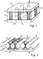
- the spring core 1 of known type shown in FIG. 1 has a central foam body 3 which is provided with cover layers 2 on both sides.
- An elastic adhesive layer 12 ensures the connection between the cover layers 2 and the foam body 3.
- These cover layers 2 can consist of a simple foam layer or additionally comprise a nonwoven layer.
- the foam body 3 has cylindrical recesses 6, in which spring elements 4 are inserted. When this spring core is subjected to a local load, the individual springs are coupled to one another by the solid foam body 3 and by the relatively stiff fiber fleece, ie they cannot really be point-elastic Act.
- Foams are not only synthetic products but also natural foam rubber or foamed latex.
- Figure 2 shows a central foam body 3, which is provided on both sides with a rib-shaped profile, the elevations 5 and depressions 7 have a complementary geometric shape.
- the cross section of the rib-shaped profile is trapezoidal and has a wider base towards the central part. It goes without saying that this trapezoidal cross section can also be designed such that the wider base lies on the side of the cover layers 2.
- the spring elements 4 are mounted in the respective recesses 7, i.e. are not coupled together by the foam body 3 and ensure good point elasticity.
- the individual spring elements 4 are adapted to the flank profile of the profile and have a biconical shape in the embodiment shown. In order to ensure the exact positioning of the springs within the spring core, the winding ends of the individual spring elements 4 protrude above the elevations 5 and rest on the end faces 11 of these elevations.
- the respective cover layers 2 are glued to the end faces 11 of the elevations 5 of this profile. Through this gluing, the spring ends are held in their position and cannot slide out of their position and touch each other, even in the event of extreme compressions or deflections of the entire spring core. In addition, this fixation prevents the spring elements from rubbing against the cover layers and damaging them after prolonged use.
- the ribs running parallel to one another on both sides of the foam body 3 lead on the one hand to a stiffening of the entire spring core in the direction of the ribs 5 and at the same time to a greater flexibility transversely to this direction.
- the complementary is essential to the invention Geometric shape of the elevations 5 and depressions 7 of the profile, since there is no undesired cutting waste during the production of this central foam body 3. This special geometric design also leads to cross ventilation, which facilitates the noiseless escape of air under extreme loads.
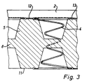
- Figure 3 shows a section of the preferred embodiment.
- This has a central foam body 3 with ribs 5, the trapezoidal cross section of which tapers towards the top layer 2.
- a spiral spring 4 is used, the uppermost end of the winding 13 rests on the end face 11 of the profile elevation 5.
- These spiral springs 4 are preferably preloaded such that they act against the spring force of the foam body ribs 5. It is thereby achieved that the springing behavior inherent in the spring elements is dampened by the elasticity of the foam.
- the hardness of the springs can be chosen according to requirements and is essentially determined by the thickness of the spring wire. In the preferred embodiments, springs with a wire thickness of 1.4 to 2.6 mm are used.
- the maximum diameter of these springs is 60mm, but can of course be adapted to the geometry of the foam body.
- Plastic foams of 20-70 kg / m 3 are preferably used as the foam body.
- the profiled foam body 3 has, for example, a total height of 10 cm, the central web 8 of which has a thickness of 15 mm.
- the height of the individual springs 4 is adapted to this overall height of the foam body and varies in the preferred embodiments between 6 cm and 14 cm.
- the adhesive layer 12 creates a connection between the end faces 11 of the elevations 5 and the cover layer 2, such that the winding end 13 is held in place.
- these cover layers 2 consist of foam with a thickness of approximately 25 mm, so that the entire innerspring can be reduced to a height of 11cm.
- a significant advantage in the combination of foam with metallic springs is the fact that the elasticity of the plastic foam, which usually diminishes in the longer term, can be maintained through the dimensional stability of the spiral springs.
- spring elements can be selected and used in accordance with the application.
- biconical, cylindrical or barrel-shaped spring elements can be used. It is also in the technical ability to combine individual springs into groups in order to adapt the spring-elastic properties to the desired load profiles. It goes without saying that the person skilled in the art would also consider rubber springs or similar elastic elements instead of the spiral springs.
- the foam body can be cut from one piece or constructed from several different layers. The recesses of the ribbed foam body can be slotted in a suitable manner for easier assembly of the spring elements. The flanks of the individual ribs can be adapted to the shape of the spring. It is also within the skill in the art to choose an adhesive with the desired elasticity for the adhesive layer 12.
Landscapes
- Springs (AREA)
- Mattresses And Other Support Structures For Chairs And Beds (AREA)
- Chair Legs, Seat Parts, And Backrests (AREA)
- Prostheses (AREA)
Abstract
Description
Die vorliegende Erfindung betrifft einen Federkern nach Anspruch 1 und insbesondere einen mehrlagigen Federkern mit einem zentralen Schaumstoffkörper, in welchem eine Vielzahl von Federelementen eingesetzt sind, sowie ein Polsterelement mit einem solchen Federkern.The present invention relates to a spring core according to claim 1 and in particular to a multi-layer spring core with a central foam body, in which a plurality of spring elements are used, and a cushion element with such a spring core.
Solche Federkerne finden ihre Verwendung in der Möbelindustrie und werden insbesondere als Kernstück in Matratzen oder Polstermöbeln eingesetzt. Diese Kernstücke sind massgebend für die Lebensdauer und Härte der Möbelstücke und werden in der Regel mit einer den Liege- oder Sitzkomfort bestimmenden Polsterschicht versehen, bevor sie mit einem festen Drell überzogen werden. Bei modernen Federkernen werden aus Kostengründen, neben Schaumgummi oder geschäumtem Latex, vermehrt synthetische Schaumstoffe verwendet. Leider lässt die Stauchhärte und damit auch die Federkraft dieser Schaumstoffe nach kurzer Zeit merklich nach und macht diese für die Anwendung in stark beanspruchten Möbelstücken ungeeignet. Verbesserte Federkerne bestehen deshalb aus einer Kombination von Schaumstoff und Federelementen.Such spring cores are used in the furniture industry and are used in particular as a core element in mattresses or upholstered furniture. These core pieces are decisive for the lifespan and hardness of the pieces of furniture and are usually provided with a cushion layer that determines the lying or sitting comfort before they are covered with a firm drill. In the case of modern innersprings, synthetic foams are increasingly being used in addition to foam rubber or foamed latex for reasons of cost. Unfortunately, the compression hardness and thus the spring force of these foams noticeably diminish after a short time, making them unsuitable for use in heavily used furniture. Improved spring cores therefore consist of a combination of foam and spring elements.
So werden heute bspw. bei Eisenbahn- oder Flugzeugsitzen Federkerne verwendet, bei denen metallische Federn direkt in einem Schaumstoffkörper eingeschäumt sind. Damit kann gegenüber den reinen Schaumstoff-Federkernen die Lebensdauer verlängert werden; komfortable und kostengünstige Sitz- oder Liegemöbel können damit jedoch nicht hergestellt werden. Das direkte Einschäumen der Federelemente erfordert aufwendige Werkzeugmaschinen und verteuert die Fertigung, insbesondere bei kleineren Produktionsmengen. Ausserdem erweist es sich als wesentlich für den Komfort bei Liege- und Sitzmöbeln, dass diese über eine gute Punktelastizität verfügen, d.h. eine ausgeprägte lokale Federkraft aufweisen. Durch das Einschäumen der Federelemente werden diese jedoch miteinander gekoppelt und können damit einem lokalen Belastungsprofil nicht mehr unabhängig voneinander folgen. Ausserdem leidet bei dieser Art Verbundfederkerne der Schaumstoff im Bereich der metallischen Federelemente und müssen diese Verbundfederkerne bei starker Benutzung häufig ersetzt werden.For example, spring cores are used today in railroad or airplane seats, in which metallic springs are directly foamed in a foam body. In this way, the service life can be extended compared to pure foam innersprings; However, comfortable and inexpensive seating or reclining furniture cannot be manufactured with it. The direct foaming in of the spring elements requires complex machine tools and increases the cost of manufacture, especially in the case of smaller production quantities. In addition, it has proven essential for the comfort of reclining and seating furniture that they have good point elasticity, that is to say they have a pronounced local spring force. By foaming the spring elements, however, these are coupled to one another and can therefore no longer be a local load profile independently of one another consequences. In addition, the foam in the area of the metallic spring elements suffers from this type of composite spring cores and these composite spring cores often have to be replaced when used heavily.
Es ist deshalb auch schon vorgeschlagen worden, aus einem zentralen Schaumstoffkörper zylindrische Hohlräume auszustanzen und in diese Stanzlöcher spiralige Federelemente einzulegen. Dieser zentrale Schaumstoffkörper ist beidseitig mit dünneren Schaumstoffschichten, sogenannten Decklagen beklebt. Damit ist einerseits gewährleistet, dass zwischen den einzelnen Federelementen keine wesentliche Feder-Kopplung auftritt und der Federkern in gewünschter Weise punktelastisch wirken kann. In einer komfortableren Ausführungsform ist zwischen dem zentralen Schaumstoffkörper und den geschäumten Deckschichten ein dünnes Faser- oder Nadelvlies als Polsterträger eingeklebt. Leider zeigen sich auch bei dieser Art kombinierter Federkerne nach längerem Gebrauch unerwünschte Verschleisserscheinungen an den Deckschichten, resp. Polsterträgern im Auflagebereich der einzelnen Federelemente und fällt bei der Produktion derartiger Federkerne eine beträchtliche Menge an Schaumstoffresten an, die nicht ohne weiteres genutzt werden können.It has therefore already been proposed to punch cylindrical cavities out of a central foam body and to insert spiral spring elements into these punch holes. This central foam body is covered on both sides with thinner foam layers, so-called cover layers. This ensures on the one hand that there is no substantial spring coupling between the individual spring elements and that the spring core can act in a desired manner in a point-elastic manner. In a more comfortable embodiment, a thin fiber or needle fleece is glued in between the central foam body and the foamed cover layers as a cushion carrier. Unfortunately, this type of combined innerspring also shows undesirable signs of wear on the cover layers after prolonged use. Upholstery carriers in the contact area of the individual spring elements and a considerable amount of foam residues accumulates in the production of such spring cores, which can not be used easily.
Mit den heutigen Wohn- und Schlafgewohnheiten besteht neben der angenehm empfundenen Punktelastizität ausserdem der Wunsch nach möglichst dünnen und leichten Polstern. Diese sollten einerseits nicht nachfedern und andererseits ihre Form auch längerfristig beibehalten. Leider zeigt es sich, dass bei solchen dünnen Polstern mit Kombinationsfederkernen deren metallische Spiralfedern bei starker Belastung derart gestaucht werden, dass deren einzelne Windungen direkt aufeinanderstossen. Dies führt insbesondere bei der Verwendung von miteinander verbundenen Federelementen (Bonelsystemen) zu unerwünschten metallischen Geräuschen.With today's living and sleeping habits, in addition to the pleasantly felt point elasticity, there is also the desire for thin and light cushions. On the one hand, these should not spring back and on the other hand should also retain their shape over the long term. Unfortunately, it turns out that in the case of such thin upholstery with combination spring cores, their metallic spiral springs are compressed in such a way that their individual turns collide directly when subjected to heavy loads. This leads to undesirable metallic noises, especially when using interconnected spring elements (Bonel systems).
Es ist deshalb Aufgabe der vorliegenden Erfindung einen kostengünstigen und verschleissarmen Polsterkern mit guter Punktelastizität zu schaffen, welcher für die Verwendung in dünnen Polsterelementen geeignet ist. Insbesondere soll ein Kombinationsfederkern mit einem zentralen Schaumstoffkörper geschaffen werden, bei dessen Herstellung keine systematisch erzeugten Abfallstücke anfallen und mit welchem Federkern geräuschlose und frei dimensionierbare Polsterelemente hergestellt werden können.It is therefore an object of the present invention to provide an inexpensive and low-wear cushion core with good point elasticity, which is suitable for use in thin cushion elements. In particular, a combination spring core with a central foam body is to be created, in the production of which no systematically generated waste pieces are produced and with which spring core silent and freely dimensionable cushion elements can be produced.
Diese Aufgabe wird erfindungsgemäss durch einen Federkern mit den Merkmalen des Anspruchs 1 gelöst. Dabei ist der zentrale Schaumstoffkörper in besonderer Weise beidseitig profiliert, d.h. weisen die Erhebungen und Vertiefungen des jeweiligen Profils eine komplementäre geometrische Form auf. An denjenigen Stellen, an denen sich Vertiefungen gegenüberliegen sind Federelemente, vorzugsweise metallische Spiralfedern, eingesetzt. Diese besondere Form des zentralen Schaumstoffkörpers und der verwendeten Spiralfedern gewährleistet darüberhinaus eine positionsgenaue Montage der Federelemente innerhalb dieses Schaumstoffkörpers, da diese Federelemente so geformt und dimensioniert sind, dass diese mit ihren Enden auf den Erhebungen des Schaumstoffkörperprofils aufliegen. In einer bevorzugten Ausführungsform sind die Spiralfedern vorgespannt und können auf die Erhebungen des Schaumstoffkörperprofils aufgespannt werden.This object is achieved according to the invention by a spring core with the features of claim 1. The central foam body is profiled on both sides in a special way, i.e. the elevations and depressions of the respective profile have a complementary geometric shape. Spring elements, preferably metallic spiral springs, are used at those points where depressions lie opposite one another. This special shape of the central foam body and the spiral springs used also ensures that the spring elements are installed in the correct position within this foam body, since these spring elements are shaped and dimensioned such that their ends rest on the elevations of the foam body profile. In a preferred embodiment, the spiral springs are preloaded and can be clamped onto the elevations of the foam body profile.
Die erfindungsgemässe Konstruktion führt dazu, dass beim Aufkleben der Deckschichten, resp. Polsterträger, im folgenden auch Decklagen genannt, auf den Schaumstoffkörper die Enden der Spiralfedern zwischen diesen Decklagen und dem Schaumstoffkörper festgehalten werden. Solchermassen eingesetzte und fixierte Spiralfedern liegen auch nach intensivem und längerem Gebrauch positionsgenau und berührungsfrei nebeneinander und können sich nicht mit den Decklagen reiben. Ihr Schwingungsverhalten kann durch den Schaumstoffkörper und die Decklagen in gewünschter Weise gedämpft werden. Das Aufliegen der einzelnen Spiralengänge der Spiralfedern aufeinander bei extremer Belastung oder niedriger Bauhöhe wird durch eine doppelkonische Form der Spiralfedern einerseits und durch den in der Mitte liegenden Schaumstoffteil verhindert.The construction according to the invention leads to the fact that when the cover layers, respectively. Upholstery carrier, also called cover layers below, on the foam body, the ends of the spiral springs between these cover layers and the foam body are held. Spiral springs used and fixed in this way lie next to each other precisely and without contact even after intensive and prolonged use and cannot rub against the cover layers. Your vibration behavior can by the Foam body and the top layers are damped in the desired manner. The double-conical shape of the spiral springs on the one hand and the foam part in the middle prevent the individual spiral flights of the spiral springs from resting on top of one another under extreme loads or low installation heights.
Erfindungsgemäss sind die Erhebungen des Schaumstoffkörperprofils beidseitig als parallel verlaufende Rippen ausgebildet. Diese Rippen weisen zu ihren Zwischenräumen eine komplementäre geometrische Gestalt auf, wodurch eine abfallarme Fabrikation realisiert werden kann und sich die Produktionskosten senken lassen. Diese Rippen wirken darüberhinaus in ihrer Längsrichtung versteifend und erlauben es gleichzeitig den Federkern in Querrichtung ohne grossen Kraftaufwand umzubiegen, wie dies bei Liegen mit hochstellbaren Kopf- und/oder Fussenden erwünscht ist. Beim Umbiegen kann die Polsterschicht in die Zwischenräume des gerippten Schaumstoffkörpers ausweichen und erhöht damit die Flexibilität des gesamten Polsterelementes quer zur Laufrichtung der Rippen.According to the invention, the elevations of the foam body profile are formed on both sides as parallel ribs. These ribs have a complementary geometric shape to their gaps, whereby low-waste production can be realized and the production costs can be reduced. In addition, these ribs have a stiffening effect in their longitudinal direction and at the same time allow the spring core to be bent in the transverse direction without great effort, as is desired in the case of beds with adjustable head and / or foot ends. When bending, the cushion layer can escape into the spaces between the ribbed foam body and thus increases the flexibility of the entire cushion element transverse to the direction of the ribs.
Durch die individuelle Fixierung der Federelemente in den Zwischenräumen dieser Rippen wird ausserdem eine optimale Punktelastizität erzeugt und lässt sich der Federkern in einfacher Weise konfektionieren, d.h. in gewünschte Grössen zerschneiden.The individual fixation of the spring elements in the spaces between these ribs also creates optimal point elasticity and the spring core can be assembled in a simple manner, i.e. cut into desired sizes.
Weitere Vorteile dieser Art verschleissarmer Kombinationsfederkerne sind für den Fachmann unmittelbar ersichtlich und sind nicht nur in der abfallfreien Herstellungsweise und der freien Dimensionierbarkeit zu sehen, sondern liegen insbesondere auch in der geräuschlosen Funktionsweise sowie der verbesserten Querbelüftung. Bei herkömmlichen Kombinationsfederkernen kann die in den Hohlräumen liegende Luft nicht frei zirkulieren und entweicht bei Belastung nicht immer geräuschlos. Die erfindungsgemässe Konstruktion erlaubt eine gute Belüftung des gesamten Polsterelementes.Further advantages of this type of low-wear combination spring cores are immediately apparent to the person skilled in the art and can be seen not only in the waste-free production method and the free dimensioning, but also in particular in the silent functioning and the improved cross ventilation. With conventional combination spring cores, the air in the cavities cannot circulate freely and does not escape when loaded always silent. The construction according to the invention allows good ventilation of the entire cushion element.
Es versteht sich, dass darüberhinaus physikalischen Eigenschaften des für den Schaumstoffkörpers oder die Decklagen verwendeten Schaumstoffs in gewünschter Weise vom Fachmann gewählt werden und die Federstärken resp. Federformen den gewünschten Anforderungen angepasst werden können. Insbesondere können einzelne Federn zu Federgruppen zusammengefasst werden, um einem individuellen Belastungsprofil entsprechen zu können oder können zusätzliche Polster- oder Federlagen vorgesehen werden.It goes without saying that the physical properties of the foam used for the foam body or the cover layers are selected in a desired manner by a person skilled in the art and the spring strengths or. Spring shapes can be adapted to the desired requirements. In particular, individual springs can be combined into spring groups in order to be able to correspond to an individual load profile or additional cushion or spring layers can be provided.
Im folgenden soll die Erfindung anhand eines Ausführungsbeispiels und mit Hilfe der Figuren näher erläutert werden. Dabei zeigt:
- Fig. 1
- ein Kombinations-Federkern bekannter Art;
- Fig. 2
- eine bevorzugte Ausführungsform eines erfindungsgemässen Kombinations-Federkerns;
- Fig. 3
- ein Ausschnitt aus der in Fig, 2 dargestellten bevorzugten Ausführungsform.
- Fig. 1
- a combination spring core of a known type;
- Fig. 2
- a preferred embodiment of a combination spring core according to the invention;
- Fig. 3
- a section of the preferred embodiment shown in Fig. 2.
Der in Figur 1 gezeigte Federkern 1 bekannter Art weist einen zentralen Schaumstoffkörper 3 auf, der beidseitig mit Decklagen 2 versehen ist. Eine elastische Klebschicht 12 gewährleistet die Verbindung zwischen den Decklagen 2 und dem Schaumstoffkörper 3. Diese Decklagen 2 können aus einer einfachen Schaumstoffschicht bestehen oder zusätzlich eine Faservliesschicht umfassen. Der Schaumstoffkörper 3 weist zylindrische Ausnehmungen 6 auf, in welche Federelemente 4 eingesetzt sind. Bei einer lokalen Belastung dieses Federkerns werden die einzelnen Federn durch den massiven Schaumstoffkörper 3 und durch das relativ steife Faservlies miteinander gekoppelt, d.h. können nicht wirklich punktelastisch wirken. Als Schaumstoffe kommen nicht nur synthetische Produkte sondern auch natürlicher Schaumgummi oder geschäumter Latex in Frage.The spring core 1 of known type shown in FIG. 1 has a
Demgegenüber zeigt Figur 2 einen zentralen Schaumstoffkörper 3, welcher beidseitig mit einem rippenförmigen Profil versehen ist, dessen Erhebungen 5 und Vertiefungen 7 eine komplementäre geometrische Form aufweisen. Im dargestellten Ausführungsbeispiel ist der Querschnitt des rippenförmigen Profils trapezförmig und weist zum zentralen Teil hin eine breitere Basis auf. Es versteht sich, dass dieser trapezförmige Querschnitt auch so ausgestaltet sein kann, dass die breitere Basis an der Seite der Decklagen 2 liegt. Die Federelemente 4 sind in den jeweiligen Vertiefungen 7 angebracht, d.h. werden vom Schaumstoffkörper 3 nicht miteinander gekoppelt und gewährleisten eine gute Punktelastizität. Die einzelnen Federelemente 4 sind dem Flankenverlauf des Profils angepasst und weisen in der dargestellten Ausführungsform eine bikonische Form auf. Um die genaue Positionierung der Federn innerhalb des Federkerns sicherzustellen, ragen die Windungsenden der einzelnen Federelemente 4 über die Erhebungen 5 und liegen auf den Stirnflächen 11 dieser Erhebungen auf.In contrast, Figure 2 shows a
Die jeweiligen Decklagen 2 sind mit den Stirnflächen 11 der Erhebungen 5 dieses Profils verklebt. Durch diese Verklebung werden die Federenden in ihrer Position gehalten und können auch bei extremen Stauchungen oder Auslenkungen des gesamten Federkerns nicht aus ihrer Lage rutschen und sich gegenseitig berühren. Darüberhinaus werden die Federelemente durch diese Fixierung daran gehindert an den Decklagen zu scheuern und diese nach längerem Gebrauch zu beschädigen. Die beidseitig des Schaumstoffkörpers 3 parallel zueinander verlaufenden Rippen führen einerseits zu einer Versteifung des gesamten Federkerns in Richtung der Rippen 5 und gleichzeitig zu einer höheren Flexibilität quer zu dieser Richtung. Erfindungswesentlich ist die komplementäre geometrische Form der Erhebungen 5 und Vertiefungen 7 des Profils, da damit bei der Herstellung dieses zentralen Schaumstoffkörpers 3 keine unerwünschten Schneidabfälle anfallen. Diese besondere geometrische Ausgestaltung führt darüberhinaus zu einer Querbelüftung, welche das geräuschlose Entweichen der Luft bei extremer Belastung erleichtert.The
Figur 3 zeigt einen Ausschnitt aus der bevorzugten Ausführungsform. Diese weist einen zentralen Schaumstoffkörper 3 auf mit Rippen 5, deren trapezförmiger Querschnitt sich zur Decklage 2 verjüngt. In dem komplementär geformten Zwischenraum ist eine Spiralfeder 4 eingesetzt, dessen oberstes Windungsende 13 auf der Stirnfläche 11 der Profilerhebung 5 aufliegt. Vorzugsweise sind diese Spiralfedern 4 vorgespannt, derart dass diese gegen die Federkraft der Schaumstoffkörperrippen 5 wirken. Dadurch wird erreicht, dass das den Federelementen eigene Nachschwingverhalten durch die Elastizität des Schaumstoffs gedämpft wird. Die Härte der Federn kann den Bedürfnissen entsprechend gewählt werden und wird im wesentlichen durch die Stärke des Federdrahts bestimmt. In den bevorzugten Ausführungsformen werden Federn mit einer Drahtstärke von 1.4 bis 2.6mm eingesetzt. Der maximale Durchmesser dieser Federn beträgt hier 60mm, kann aber selbstverständlich der Geometrie des Schaumstoffkörpers angepasst werden. Vorzugsweise werden als Schaumstoffkörper Kunststoffschäume von 20 - 70 kg/m3 verwendet. Der profilierte Schaumstoffkörper 3 weist beispielsweise eine Gesamthöhe von 10cm auf, wobei dessen Mittelsteg 8 eine Dicke von 15mm aufweist. Die Höhe der einzelnen Federn 4 ist an diese Gesamthöhe des Schaumstoffkörpers angepasst und variiert in den bevorzugten Ausführungsformen zwischen 6cm und 14cm. Die Klebschicht 12 schafft eine Verbindung zwischen den Stirnflächen 11 der Erhebungen 5 und der Decklage 2, derart dass das Windungsende 13 an Ort gehalten wird. Diese Decklagen 2 bestehen in einer einfachen Ausführungsform aus Schaumstoff mit einer Dicke von ca. 25mm, so dass der gesamte Federkern auf eine Höhe von 11cm reduziert werden kann. Durch die an die Form der Zwischenräume angepasste Form der Federlemente 4 wird vermieden, dass die Federelemente 4 an dem Schaumstoffkörper 3 reiben und diesen verletzen. Ein wesentlicher Vorteil in der Kombination von Schaumstoff mit metallischen Federn ist darin zu sehen, dass die in der Regel längerfristig nachlassende Spannkraft des Kunststoffschaums durch die Formstabilität der Spiralfedern aufrechterhalten werden kann.Figure 3 shows a section of the preferred embodiment. This has a
Durch die unabhängige Positionierung der metallischen Federn erweist sich ein derartiger Federkern ausserdem als einfach konfektionierbar, d.h. kann dieser um die Federn herum in beliebiger Weise zugeschnitten werden. Durch die doppelkonische Form der Spiralfedern und die dünne Schaumstoffschicht des Schaumstoffkörpers im mittleren Bereich der Federelemente können deren Windungen bei extremer Belastung nicht aufeinander zu liegen kommen.Due to the independent positioning of the metallic springs, such a spring core also proves to be easy to assemble, i.e. can be cut around the springs in any way. Due to the double-conical shape of the spiral springs and the thin foam layer of the foam body in the middle area of the spring elements, their turns cannot come to rest on each other under extreme loads.
Es versteht sich, dass der Anwendung entsprechend verschieden geformte Federelemente gewählt und eingesetzt werden können. So können bspw. bikonische, zylindrische oder tonnenförmige Federelemente eingesetzt werden. Ebenso liegt es im fachmännischen Können, einzelne Federn zu Gruppen zusammenzufassen, um die federelastischen Eigenschaften gewünschten Belastungsprofilen anzupassen. Dabei versteht es sich, dass der Fachmann anstelle der Spiralfedern auch Gummifedern oder ähnliche elastische Elemente in Betracht ziehen würde. Ebenso kann der Schaumstoffkörper aus einem Stück geschnitten oder aus mehreren unterschiedlichen Schichten aufgebaut sein. Zur einfacheren Montage der Federelemente können die Vertiefungen des gerippten Schaumstoffkörpers in geeigneter Weise geschlitzt sein. Die Flanken der einzelnen Rippen können der Federform angepasst werden. Ebenso liegt es im fachmännischen Können, einen Klebstoff mit gewünschter Elastizität für die Klebschicht 12 zu wählen.It goes without saying that differently shaped spring elements can be selected and used in accordance with the application. For example, biconical, cylindrical or barrel-shaped spring elements can be used. It is also in the technical ability to combine individual springs into groups in order to adapt the spring-elastic properties to the desired load profiles. It goes without saying that the person skilled in the art would also consider rubber springs or similar elastic elements instead of the spiral springs. Likewise, the foam body can be cut from one piece or constructed from several different layers. The recesses of the ribbed foam body can be slotted in a suitable manner for easier assembly of the spring elements. The flanks of the individual ribs can be adapted to the shape of the spring. It is also within the skill in the art to choose an adhesive with the desired elasticity for the
Claims (10)
Applications Claiming Priority (3)
| Application Number | Priority Date | Filing Date | Title |
|---|---|---|---|
| CH279/96 | 1996-02-02 | ||
| CH27996 | 1996-02-02 | ||
| CH27996 | 1996-02-02 |
Publications (2)
| Publication Number | Publication Date |
|---|---|
| EP0796580A1 true EP0796580A1 (en) | 1997-09-24 |
| EP0796580B1 EP0796580B1 (en) | 2001-03-14 |
Family
ID=4183384
Family Applications (1)
| Application Number | Title | Priority Date | Filing Date |
|---|---|---|---|
| EP97100304A Expired - Lifetime EP0796580B1 (en) | 1996-02-02 | 1997-01-10 | Spring core for cushion |
Country Status (3)
| Country | Link |
|---|---|
| EP (1) | EP0796580B1 (en) |
| AT (1) | ATE199633T1 (en) |
| DE (1) | DE59703121D1 (en) |
Cited By (2)
| Publication number | Priority date | Publication date | Assignee | Title |
|---|---|---|---|---|
| DE29719171U1 (en) * | 1997-10-29 | 1999-03-04 | Polus, Michael, Dr., 90489 Nürnberg | Solid material mattress |
| EP2296509A1 (en) * | 2008-01-18 | 2011-03-23 | Sealy Technology LLC | Innerspring dampening inserts |
Citations (3)
| Publication number | Priority date | Publication date | Assignee | Title |
|---|---|---|---|---|
| FR1110462A (en) * | 1954-09-03 | 1956-02-13 | Advanced mattress or cushion | |
| FR1593548A (en) * | 1968-06-13 | 1970-06-01 | ||
| DE2820282A1 (en) * | 1978-05-10 | 1979-11-15 | Recticel Deutsch Kunststoffe | Polyurethane foam mattress with built-in springs and air ducts - by cutting trapezoidal profile out of thick web, embedding springs, and glueing pairs of web together to form ducts |
-
1997
- 1997-01-10 EP EP97100304A patent/EP0796580B1/en not_active Expired - Lifetime
- 1997-01-10 AT AT97100304T patent/ATE199633T1/en not_active IP Right Cessation
- 1997-01-10 DE DE59703121T patent/DE59703121D1/en not_active Expired - Fee Related
Patent Citations (3)
| Publication number | Priority date | Publication date | Assignee | Title |
|---|---|---|---|---|
| FR1110462A (en) * | 1954-09-03 | 1956-02-13 | Advanced mattress or cushion | |
| FR1593548A (en) * | 1968-06-13 | 1970-06-01 | ||
| DE2820282A1 (en) * | 1978-05-10 | 1979-11-15 | Recticel Deutsch Kunststoffe | Polyurethane foam mattress with built-in springs and air ducts - by cutting trapezoidal profile out of thick web, embedding springs, and glueing pairs of web together to form ducts |
Cited By (3)
| Publication number | Priority date | Publication date | Assignee | Title |
|---|---|---|---|---|
| DE29719171U1 (en) * | 1997-10-29 | 1999-03-04 | Polus, Michael, Dr., 90489 Nürnberg | Solid material mattress |
| EP2296509A1 (en) * | 2008-01-18 | 2011-03-23 | Sealy Technology LLC | Innerspring dampening inserts |
| EP2296509A4 (en) * | 2008-01-18 | 2011-08-17 | Sealy Technology Llc | Innerspring dampening inserts |
Also Published As
| Publication number | Publication date |
|---|---|
| ATE199633T1 (en) | 2001-03-15 |
| DE59703121D1 (en) | 2001-04-19 |
| EP0796580B1 (en) | 2001-03-14 |
Similar Documents
| Publication | Publication Date | Title |
|---|---|---|
| DE102013202688B4 (en) | Seat cushion for a vehicle seat | |
| EP3393303B1 (en) | Foam core for a cushion of a seat part or a bed part or a backrest of an item of upholstered furniture or of a vehicle seat | |
| EP2139366B1 (en) | Support element for a cushion cover for seating and lying areas | |
| EP1362534B1 (en) | Support by spring mat | |
| WO2005048781A2 (en) | Support element | |
| EP1825783B1 (en) | Spring for supporting mats and supporting mat in a seat construction | |
| EP1952727A2 (en) | Upholstery made of foamed plastic | |
| EP2225973B1 (en) | Mattress spring | |
| EP0632702B1 (en) | Upholstered element | |
| DE102008055549B4 (en) | Spring element made of foam | |
| EP2110056A1 (en) | Compound assembly | |
| DE1943832A1 (en) | Padding and method of making same | |
| DE2935438C2 (en) | ||
| EP1680987A1 (en) | Padding element and spring element therefor | |
| EP0796580B1 (en) | Spring core for cushion | |
| EP0397978B1 (en) | Slat for a slat support | |
| EP0839481B1 (en) | Inner core of foamed material for upholstery and method for its manufacture | |
| WO1995002977A1 (en) | Mattress | |
| DE102010014664B4 (en) | Upholstery element, in particular a mattress | |
| EP3207830B1 (en) | Travel mattress | |
| DE102006037080B4 (en) | cushion layer | |
| EP0670128B1 (en) | Under-mattress | |
| DE20113727U1 (en) | mattress | |
| DE202011000058U1 (en) | composite component | |
| EP2022372A1 (en) | Slatted frame with lumbar support |
Legal Events
| Date | Code | Title | Description |
|---|---|---|---|
| PUAI | Public reference made under article 153(3) epc to a published international application that has entered the european phase |
Free format text: ORIGINAL CODE: 0009012 |
|
| AK | Designated contracting states |
Kind code of ref document: A1 Designated state(s): AT CH DE FR IT LI |
|
| 17P | Request for examination filed |
Effective date: 19980128 |
|
| 17Q | First examination report despatched |
Effective date: 19990622 |
|
| GRAG | Despatch of communication of intention to grant |
Free format text: ORIGINAL CODE: EPIDOS AGRA |
|
| GRAG | Despatch of communication of intention to grant |
Free format text: ORIGINAL CODE: EPIDOS AGRA |
|
| GRAH | Despatch of communication of intention to grant a patent |
Free format text: ORIGINAL CODE: EPIDOS IGRA |
|
| GRAH | Despatch of communication of intention to grant a patent |
Free format text: ORIGINAL CODE: EPIDOS IGRA |
|
| GRAA | (expected) grant |
Free format text: ORIGINAL CODE: 0009210 |
|
| AK | Designated contracting states |
Kind code of ref document: B1 Designated state(s): AT CH DE FR IT LI |
|
| REF | Corresponds to: |
Ref document number: 199633 Country of ref document: AT Date of ref document: 20010315 Kind code of ref document: T |
|
| REG | Reference to a national code |
Ref country code: CH Ref legal event code: EP |
|
| REF | Corresponds to: |
Ref document number: 59703121 Country of ref document: DE Date of ref document: 20010419 |
|
| REG | Reference to a national code |
Ref country code: CH Ref legal event code: NV Representative=s name: RITSCHER & SEIFERT |
|
| ET | Fr: translation filed | ||
| ITF | It: translation for a ep patent filed | ||
| PLBE | No opposition filed within time limit |
Free format text: ORIGINAL CODE: 0009261 |
|
| STAA | Information on the status of an ep patent application or granted ep patent |
Free format text: STATUS: NO OPPOSITION FILED WITHIN TIME LIMIT |
|
| 26N | No opposition filed | ||
| PGFP | Annual fee paid to national office [announced via postgrant information from national office to epo] |
Ref country code: FR Payment date: 20041230 Year of fee payment: 9 |
|
| PGFP | Annual fee paid to national office [announced via postgrant information from national office to epo] |
Ref country code: AT Payment date: 20050104 Year of fee payment: 9 |
|
| PGFP | Annual fee paid to national office [announced via postgrant information from national office to epo] |
Ref country code: DE Payment date: 20050113 Year of fee payment: 9 |
|
| PGFP | Annual fee paid to national office [announced via postgrant information from national office to epo] |
Ref country code: CH Payment date: 20050321 Year of fee payment: 9 |
|
| PG25 | Lapsed in a contracting state [announced via postgrant information from national office to epo] |
Ref country code: AT Free format text: LAPSE BECAUSE OF NON-PAYMENT OF DUE FEES Effective date: 20060110 |
|
| PG25 | Lapsed in a contracting state [announced via postgrant information from national office to epo] |
Ref country code: LI Free format text: LAPSE BECAUSE OF NON-PAYMENT OF DUE FEES Effective date: 20060131 Ref country code: FR Free format text: LAPSE BECAUSE OF NON-PAYMENT OF DUE FEES Effective date: 20060131 Ref country code: CH Free format text: LAPSE BECAUSE OF NON-PAYMENT OF DUE FEES Effective date: 20060131 |
|
| PGFP | Annual fee paid to national office [announced via postgrant information from national office to epo] |
Ref country code: IT Payment date: 20060131 Year of fee payment: 10 |
|
| PG25 | Lapsed in a contracting state [announced via postgrant information from national office to epo] |
Ref country code: DE Free format text: LAPSE BECAUSE OF NON-PAYMENT OF DUE FEES Effective date: 20060801 |
|
| REG | Reference to a national code |
Ref country code: CH Ref legal event code: PL |
|
| REG | Reference to a national code |
Ref country code: FR Ref legal event code: ST Effective date: 20060929 |
|
| PG25 | Lapsed in a contracting state [announced via postgrant information from national office to epo] |
Ref country code: IT Free format text: LAPSE BECAUSE OF NON-PAYMENT OF DUE FEES Effective date: 20070110 |