EP0796468B1 - Maintenance channel for modular, highly interconnected computer systems - Google Patents
Maintenance channel for modular, highly interconnected computer systems Download PDFInfo
- Publication number
- EP0796468B1 EP0796468B1 EP95933145A EP95933145A EP0796468B1 EP 0796468 B1 EP0796468 B1 EP 0796468B1 EP 95933145 A EP95933145 A EP 95933145A EP 95933145 A EP95933145 A EP 95933145A EP 0796468 B1 EP0796468 B1 EP 0796468B1
- Authority
- EP
- European Patent Office
- Prior art keywords
- sanity
- code
- module
- modules
- sanity code
- Prior art date
- Legal status (The legal status is an assumption and is not a legal conclusion. Google has not performed a legal analysis and makes no representation as to the accuracy of the status listed.)
- Expired - Lifetime
Links
Images






Classifications
-
- G—PHYSICS
- G06—COMPUTING OR CALCULATING; COUNTING
- G06F—ELECTRIC DIGITAL DATA PROCESSING
- G06F15/00—Digital computers in general; Data processing equipment in general
- G06F15/16—Combinations of two or more digital computers each having at least an arithmetic unit, a program unit and a register, e.g. for a simultaneous processing of several programs
- G06F15/163—Interprocessor communication
- G06F15/173—Interprocessor communication using an interconnection network, e.g. matrix, shuffle, pyramid, star, snowflake
- G06F15/17337—Direct connection machines, e.g. completely connected computers, point to point communication networks
- G06F15/17343—Direct connection machines, e.g. completely connected computers, point to point communication networks wherein the interconnection is dynamically configurable, e.g. having loosely coupled nearest neighbor architecture
-
- G—PHYSICS
- G06—COMPUTING OR CALCULATING; COUNTING
- G06F—ELECTRIC DIGITAL DATA PROCESSING
- G06F11/00—Error detection; Error correction; Monitoring
- G06F11/07—Responding to the occurrence of a fault, e.g. fault tolerance
- G06F11/0703—Error or fault processing not based on redundancy, i.e. by taking additional measures to deal with the error or fault not making use of redundancy in operation, in hardware, or in data representation
- G06F11/0706—Error or fault processing not based on redundancy, i.e. by taking additional measures to deal with the error or fault not making use of redundancy in operation, in hardware, or in data representation the processing taking place on a specific hardware platform or in a specific software environment
- G06F11/0709—Error or fault processing not based on redundancy, i.e. by taking additional measures to deal with the error or fault not making use of redundancy in operation, in hardware, or in data representation the processing taking place on a specific hardware platform or in a specific software environment in a distributed system consisting of a plurality of standalone computer nodes, e.g. clusters, client-server systems
-
- G—PHYSICS
- G06—COMPUTING OR CALCULATING; COUNTING
- G06F—ELECTRIC DIGITAL DATA PROCESSING
- G06F11/00—Error detection; Error correction; Monitoring
- G06F11/07—Responding to the occurrence of a fault, e.g. fault tolerance
- G06F11/0703—Error or fault processing not based on redundancy, i.e. by taking additional measures to deal with the error or fault not making use of redundancy in operation, in hardware, or in data representation
- G06F11/0751—Error or fault detection not based on redundancy
- G06F11/0763—Error or fault detection not based on redundancy by bit configuration check, e.g. of formats or tags
-
- G—PHYSICS
- G06—COMPUTING OR CALCULATING; COUNTING
- G06F—ELECTRIC DIGITAL DATA PROCESSING
- G06F11/00—Error detection; Error correction; Monitoring
- G06F11/07—Responding to the occurrence of a fault, e.g. fault tolerance
- G06F11/16—Error detection or correction of the data by redundancy in hardware
- G06F11/20—Error detection or correction of the data by redundancy in hardware using active fault-masking, e.g. by switching out faulty elements or by switching in spare elements
- G06F11/202—Error detection or correction of the data by redundancy in hardware using active fault-masking, e.g. by switching out faulty elements or by switching in spare elements where processing functionality is redundant
- G06F11/2023—Failover techniques
- G06F11/2033—Failover techniques switching over of hardware resources
-
- G—PHYSICS
- G06—COMPUTING OR CALCULATING; COUNTING
- G06F—ELECTRIC DIGITAL DATA PROCESSING
- G06F11/00—Error detection; Error correction; Monitoring
- G06F11/22—Detection or location of defective computer hardware by testing during standby operation or during idle time, e.g. start-up testing
- G06F11/26—Functional testing
- G06F11/273—Tester hardware, i.e. output processing circuits
- G06F11/2736—Tester hardware, i.e. output processing circuits using a dedicated service processor for test
Definitions
- the present invention relates to computer systems and in particular to partitioning and control of modules in modular, highly interconnected computer systems.
- Modularized, highly interconnected computing systems offer distributed memory modules and processing modules which can be separated and grouped for concurrent processing of different programs.
- Systems with a large number of processing elements are difficult to manage and control, since the large number of interconnected modules creates potential for both hardware and software failures. For instance, determination of active and functional modules is complicated by intermittent connections and connections to ports which appear connected or active when the ports are actually inactive.
- the present invention addresses the aforementioned deficiencies of the prior art and solves other problems that will be understood and appreciated by those skilled in the art upon reading and understanding the present specification.
- the present invention provides a modular computer system as claimed in claim 1.
- the present invention provides a method of intermodule control and messaging as claimed in claim 7.
- the present invention provides a module as set out in claim 15.
- the present invention includes several embodiments which provide a method and apparatus for configuration and control of a highly interconnected, modular computer system.
- One embodiment of the present invention also offers a method and apparatus for completely independent processing groups. Such flexibility allows the operator to run different programs on a plurality of machines which are independent from both a software and a hardware perspective.
- Such a system is also highly configureable and fault tolerant, since modules can be associated with various working groups without the need to rewire the interconnections.
- the system also provides a method and apparatus for ensuring that the modules associated with a processing group are functional and provides means for bypassing defective modules.
- a maintenance channel which controls both software and hardware isolation of separate processing groups.
- the maintenance channel incorporates specialized cyclical signaling between modules to indicate module functionality and arbitrate module control. These signals are called sanity codes. They are a continuous handshaking between modules for the purposes of asserting control of a module and detecting when a module has erred, either due to software or hardware failure.
- the maintenance channel also features separate lines for command transmissions and for error message transmissions.
- the sanity code method and apparatus provide a system for both hardware and software division of a modular computer system, and enable one partition of the machine to be deactivated while other partitions continue executing software tasks.
- the deactivation feature is useful to isolate portions of the computer for diagnosis, troubleshooting, repair, upgrade, or any other modification.
- Sanity codes also provide a system for automatically detecting defective modules and switching from a defective module to an operating module or re-routing necessary connections to continue processing without interruption.
- Sanity codes enhance system programmability and reconfiguration and provide a system for redundant intermodule control and communication paths.
- One embodiment of the present invention provides a system of module communications using sanity codes to identify and isolate nonfunctional modules in the system within one clock period of module failure and continue processing uninterrupted by the failure.
- One embodiment of the present invention also includes an error channel for transceiving error information between the modules.
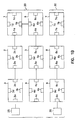
- FIG. 1A demonstrates one embodiment of a computer system 110, featuring a collection of modules 1-9 which contain a plurality of ports 1a-1d through 9a-9d.
- Modules 1-9 perform various processing tasks, including processing, data storage, and input/output functions and may be connected in a variety of different configurations using the ports and a communication network.
- U. S. Patent 5,319,775 issued to Loges et al. and entitled "Centralized Diagnostic System for Loosely Coupled Processors", describes a diagnostic system for a large, multiple processor data processing system.
- Loges' system comprises a two embedded tree structure communication networks.
- the diagnostic system described by Loges is not programmable, but rather structured to provide three bidirectional paths.
- FIG. 1A shows one embodiment where the computer 110 is divided into two processing groups comprising a first group of modules 1-6 and a second group comprising modules 7-9.
- Processing groups 20 and 30 fall on module boundaries, however, alternate embodiments include divisions of a module (intramodule boundaries).
- Control of processing group 20 is accomplished using control 25, which may be another module of the collection of modules or could be an external workstation.
- control of processing group 30 is accomplished by control 35.
- the division represents two wholly independent computing systems, from both a hardware and software perspective.
- intermodule control and communication must be wholly independent between processing group 20, comprising modules 1-6, and the processing group 30, comprising modules 7-9. Therefore, if any hardware or software problems occur in the processing group 20, the operations of operating group 30 will not be interrupted.
- This embodiment allows computer system 110 to be divided into separate processing groups which are independent in both terms of software and hardware; they are separate computers. Those skilled in the art will readily recognize that variations in configuration and number and type of modules is possible without departing from the scope of the present invention.
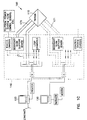
- FIG. 1C shows a modular, highly interconnected computing system 100 wherein computer 110 includes modules for processing, memory, input/output (I/O), and error detection.
- Interface electronics 140 connect the computer 110 to operator workstation 120 and maintenance workstation 130.
- Operator workstation 120 serves as a control panel for computer 110.
- Maintenance workstation 130 executes software which monitors computer 110 operation and issues commands to computer 110 over maintenance channel line 170 to configure computer 110 and to select hardware options available on computer 110, such as test points for diagnostics.
- Other embodiments feature a plurality of maintenance workstations 130 to support independent maintenance channels in computer 110. For example, a second maintenance channel line 171 is shown which provides a secondary configuration and control interface between a maintenance workstation and computer 110.
- the maintenance channel also provides control of computer system 110 using command transmit and receive lines.
- the command channel performs configuration, Master Clear controls of CPU and memory modules, system initialization, disabling sections of the system for powering, monitoring system activity, selecting test points for maintenance purposes, and initializing the system I/O resources. All of these different functions are accessed by sending an access code that addresses an individual option or chip in the system.
- every chip in the system contains up to 128 soft switches, and 128 test point selects. Every function and configuration is controlled via the soft switches and the system testing and diagnostics use the test point selects to monitor system functionality.
- the soft switches also enable intramodule partitioning.
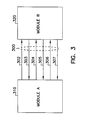
- maintenance channel line 170 is illustrated in FIG. 3.
- Two modules 310 and 320 are interconnected by maintenance channel 300.
- the maintenance channel 300 includes signals for sanity code transmit 302 (module 310 transmitting to module 320), sanity code receive 303, command transmit 304, command receive 305, error signal transmit 306, and error signal receive 307.
- sanity code transmit 302 module 310 transmitting to module 320
- command transmit 304 command receive 305
- error signal transmit 306 error signal receive 307.
- these signals must be transceived from each port independently.
- modules have several potential ports from which control signals can be received, however, the sanity code arbitration procedure (described below) is used to select a controlling or "master" port from the several candidates. Therefore, the intermodule communication and control can often be referred to as a master and slave relationship, since the module closer to the maintenance workstation in the sanity tree, the "master" module, is sending commands down the tree to the slave" module.
- each module with intelligent intermodule control and communication using a maintenance channel to manage the modules of a particular processing group and provide an interface to other processing groups without compromising the independence of its home processing group.
- each module is equipped to generate and detect a cyclical bit stream, called a sanity code, which identifies functional modules as opposed to nonfunctional modules.
- the sanity code serves as a continuous handshaking signal between a master module and its slave module(s) which indicates that the modules are operating correctly from both a hardware and software perspective.
- continuous sanity code generation prevents intermittent or inactive modules from transmitting garbage data to the rest of the system, since the sanity code generators and recognizers incorporated into the present invention are sensitive to intermittent or constant failures.
- FIG. 2 illustrates how a "tree" of modules are interrelated via the maintenance channel using sanity codes.
- a maintenance workstation 130 executes software which selects a particular sanity code to be "programmed" into generator 210 via interface electronics 140 using a 24 bit seed value.
- the sanity code can be any predetermined cyclically redundant code.
- a six (6) bit repeating code of 110010 is used as one unique sanity code.
- Maintenance channel information is distributed via the sanity tree structure, starting at the module where the maintenance workstation 130 is connected, and proceeding to computer 110 over maintenance channel line 170.
- the sanity code is generated by a sanity code generation hardware 210.
- a "sanity tree" is a series of interconnected modules which are logically active and controlled by a common maintenance channel.
- the sanity code system also requires the different parts of computer 110 to ensure sanity before allowing communication with those parts of the system. If, for example, module 240 does not receive a valid sanity code from module 230, then it will not communicate with module 230 and module 250.
- One embodiment of the present invention features sanity code generation hardware on special modules. Therefore, the number of maintenance channels is limited to the number of special modules in the computer 110.
- Another embodiment of the present invention provides specialized sanity code generation hardware inputs for a plurality of maintenance channels.
- the embodiment shown in FIG. 2 features sanity code generation hardware 210 on shared module 230 with a direct route through the module microprocessor 220.
- the route through 220 is an optional means by which sanity code generator hardware can reside on a module and enter the sanity code signals into the module maintenance channel interface.
- Other hardware realizations of the sanity code generator are possible.
- maintenance workstation 130 could include a sanity code generator.
- the maintenance channel controls the sanity codes to all the modules in the system, because it programs sanity code generation hardware 210 in order for it to properly send a valid code.
- the modules receiving the sanity code do not generate the sanity code, but retransmit the received sanity code.
- a single sanity code source ensures that each module of the tree is functioning properly, because the sanity code originates from one source and each module must operate properly to receive and retransmit the sanity code.
- a failure at any intermediate module in the sanity tree causes a collapse of the modules beneath it (modules receiving a sanity code from the failing module will cease receiving the sanity code upon failure of that module). If another module is reconfigured in place of the failing module, the modules below the failing module receive the proper sanity code sequence and the sanity tree structure is preserved.
- the maintenance channel configures the sanity tree by issuing a command to each module over the command channel which instructs the module to retransmit the sanity code to other modules in the computer 110.
- This command enables the maintenance channel to activate or idle portions of the system. Therefore, access to various parts of the system to set memory configurations, CPU numbers, etc., is restricted until a sanity code is sent to each module to be configured.
- the integrity of the system is protected by causing all inactive modules to stay in a reset state until activated by another module transmitting a valid sanity code. This prevents the module from transmitting garbage information until it is formally connected to the sanity code tree. It also ensures an orderly start-up of the modules in computer 110, or portions thereof. Each module is initially activated in a default mode, unless instructed otherwise by the command channel.
- sanity code generation hardware 210 is programmed by maintenance workstation 130 over maintenance channel line 170 to generate a sanity code.
- the sanity code is transferred to module 230 via route through 220 so that module 230 receives the proper sanity code from sanity code generation hardware 210.
- Communication between maintenance workstation 130 and module 230 is established once module 230 returns the proper sanity code to the sanity code generator hardware 210. Once this communication is established, module 230 is programmed to pass on the sanity code to module 240.
- Communication is established between modules 230 and 240 once module 240 begins transmitting the proper sanity code to module 230. Then module 240 is programmed to transmit the sanity code to module 250. Module 250 retransmits the sanity code to module 240 and communication is established with module 250. A slave module will not return the proper sanity code to the master module if it is not functioning properly.
- the flexibility of establishing the tree structure at configuration time enables the maintenance workstation to bring up a system in any combination of module interconnection.
- No tree structure is fixed by the hardware and therefore, partially configured and partially populated systems can be powered up, instead of the entire machine. This allows an operator to place a portion of the system under test, while running several other operations with the remaining portions of the system. The operator may also test different operating systems on independent maintenance channels.
- modules are activated and the remaining inactive modules receive a number of potential sanity codes signals from interconnected active modules.
- An arbitration scheme is necessary to ensure that a module which is being powered up is associated with another module in an orderly fashion.
- modules 410 and 430 are active and sending sanity codes across maintenance channels 412 and 432, to ports 414 and 434, respectively.
- Module 420 is inactive and must decide which sanity code to accept.
- One embodiment of the arbitration electronics 440 is shown in FIG. 5.
- Arbitration electronics 440 comprise sanity code recognizers 510 and 520 for sanity code inputs from ports 414 and 434, respectively.
- Command code recognizers 512 and 522 also receive commands from ports 414 and 434.
- first sanity code detect arbiter 530 detects the first valid sanity code and command combination arriving at module 420. Control of the module 420 is given to the first interconnected module providing a valid sanity code and retransmit command. For instance, if control is given to port 414 (module 410 of FIG. 4), then multiplexer 540 passes commands from command code recognizer 512 to command decoder 545.
- the incoming module commands may include a command to close switch 517 to return a sanity code to the transmitting module (module 410, in this example). If port 434 (module 430 of FIG. 4) received control, then multiplexer 540 passes commands from command code recognizer 522 to command decoder 545. The incoming module commands may include a command to close switch 527 to return a sanity code to the transmitting module (module 430, in this example).
- Alternate embodiments include re-arbitration commands to allow a module re-negotiate control to another master module.
- the controlling maintenance channel re-arbitrates control of the module by sending a command to arbitration electronics 440 to retransmit the sanity code of the opposite channel, to transfer control to the other module. For instance, if module 410 had control of module 420, instead of closing switch 517, a command could be sent by the maintenance channel 412 to close switch 527, thereby re-arbitrating control to module 430 (and maintenance channel 432).
- sanity codes could be hierarchical in nature such that one code would have precedence over the other in arbitration situations.
- FIG. 6 shows one embodiment of a sanity code generation method and apparatus, according to the present invention.
- Sanity code generator 600 of FIG. 6 is included in sanity code generation electronics 210 of FIG. 2.
- the command to start sanity code generation is captured in command register 610.
- Command decoder 620 detects a request to start the sanity code generator 600, and enters a portion of the command into shift register 615.
- key value detector 624 compares the remaining portion of the command in command register 610 to an expected value. If the proper value in register 610 is not detected, then command decoder 620 will force gate 628 to reset shift register 615. If the proper value is in command register 610, then shift register 615 will not be reset and the bit pattern in shift register 615 will recirculate and the sanity code is repeated at output 629 at the appropriate sanity code pattern and rate.
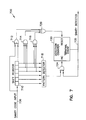
- FIG. 7 shows one embodiment of a sanity code recognizer 700.
- Sanity code recognizer 700 could be used for sanity code recognizers 510 or 520 of FIG. 5.
- the sanity code to be detected arrives at shift register 710. If a valid code is detected for an adequate number of cycles, output 735 is set to logical one to signal a valid sanity code to its module.
- Shift register 710 accumulates a six bit pattern from sanity code input 736 and pattern detector 718 compares the accumulated bit pattern to an expected sanity code. Upon detection of a valid sanity code, pattern detector 718 increments detection counter 730 via AND gate 734 if the terminal count of detection counter 730 has not been reached. If detection counter 730 has reached terminal count, signalling a valid sanity code on output 735, then AND gate 734 prevents further incrementing of detection counter 730.
- OR gate 720 Three inputs to OR gate 720 reset detection counter 730, either resetting a valid sanity code signal on output 735 or preventing a terminal count of detection counter 730.
- AND gate 714 will output a logical one if the received pattern contains more consecutive logical ones than the predetermined sanity code allows. If the pattern contains more consecutive zeros than expected, then AND gate 716 (with inverted inputs as shown in FIG. 7) will output a logical one.
- EXCLUSIVE-OR (XOR) gate 712 detects if the received pattern does not repeat at the same cyclical rate as the length of shift register 710.
- OR gate 720 will output a logical one and reset the detection counter 730, which prevents detection counter 730 from signaling a valid sanity code at output 735.
- a continuous stream of valid sanity codes generate a terminal count of detection counter 730 and a valid sanity code signal at output 735.
- One embodiment of the present invention analyzes 16 repetitions of 6 bit cycles to verify that the module is indeed active and not intermittently transmitting the proper sanity code.
- the value of the terminal count may be increased or decreased to vary the required number of sanity code cycles to be received before outputting a valid sanity code signal to the module.
- FIG. 8 shows one embodiment of a sanity code resynchronizer 800.
- Sanity codes which arrive on input 845 are received by detector 810.
- Sanity codes arriving on input 847 are received by detector 820.
- NOR gate 840 forces counter 841 (which is free running, and cycles in counts equal to the number of bits in a sanity code pattern) into a reset state.
- counter 841 When either of the detectors 810 or 820 detects a valid sanity code, counter 841 will begin free running, and the relative bit shift between the sanity codes will be captured when the second detector receives a valid sanity code.
- register 816 directs multiplexer 814 to the zeroth tap of shift register 812 labeled as input 850, thus selecting a non-shifted output for output 844.
- register 826 will capture a two (2) value and multiplexer 824 will connect the second tap of shift register 822, labeled as 852, to output 846. This positioning of taps places the sanity code bitstreams in synchronization. Therefore, all the sanity code outputs from a resynchronizer 800 are identical after resynchronization.
- One application of a resynchronizer is to synchronize sanity codes received from different sources to prevent a loss of proper sanity code input in case of a voluntary or involuntary handoff by the master module.
- the sanity trees formed by intermodule linkage via the sanity code are responsible for establishing a command structure to the modules.
- hardware switches and options installed in each module are the means for partitioning the system into separate and independent hardware processing groups.
- the sanity codes provide a system which establishes contact with select modules, and ensures continued, faultless control and communication with those modules.
- the command channel directly programs the modules, which enables the modules to be easily reconfigured while simultaneously providing independent hardware operation of each processing group.
- messages and commands are sent to the various modules in the sanity tree using the command channel of the maintenance channel interface.
- Messages and commands are sent using a route code prefix to address the message or command to the correct module in the tree.
- Route codes are systematically stripped from the message or command as they travel down the tree from the maintenance channel to the target module.
- FIG. 9 shows one embodiment of the format for maintenance channel messages and commands. Segment 93 of word 95 contains command and message information. Words 96 through 97 are added as needed for each command in a predetermined format. A greater number of words may be added without departing from the scope of the present invention.
- Route codes in route segment 92 precede the message and command data in word 95. In this embodiment individual route codes are 5 bits long. The remainder of the word is filled with zeros 91.
- the route codes are used in routing the message from module to module down the sanity tree and are stripped off the front end of the route segment 92 and zeros are padded in. As the message or command is sent down the tree the modules look for the first non-zero character to signify the beginning of the route code.
- FIG. 10 shows one embodiment of a route code forwarder/stripper 101.
- Shift register 119 receives an incoming serial data maintenance channel message on input 123.
- Upon detection of the first non-zero bit counter 112 receives shift pulses from shift register 119.
- the shift register 119 contains the leading route code which is forwarded to register 114.
- the routing code in register 114 drives the demultiplexer 116 to direct the remaining bit stream to another module or to an option on the present module.
- the bit stripping function is not shown in FIG 10.
- a special condition occurs when gate 118 detects an octal 37 it does not enter the route code into register 114 and does not strip the route code from the route segment 92 (of FIG. 9).
- octal 37 is the code for a continuation route code.
- the continuation route code is designed to follow the same trail followed by the prior maintenance channel message, and is used as a header for data words 1 through N (96 through 97, as shown in FIG. 9), when necessary.
- Counter 112 may count to any number over 64, since the number of bits in the basic maintenance channel message format is 64 bits, plus the five potential bits used for the continuation route code. Therefore, the 72 is in excess of 69, which is the total worst case number of bits traveling through in one maintenance channel message word.
- One advantage in using the demultiplexer 116 to route commands and messages is that if the sanity tree structure is known, then all addresses for any option or module on the tree are relative and an extra absolute addressing scheme to uniquely identify each module is unnecessary.
- the routing codes may be used to address different options on a module.
- the codes may be stacked to address different soft switches on a module.
- Uses for soft switches include:
- Commands sent over the command channel are used to configure each module in the sanity tree. If no configuration is sent to the modules, then they are activated in their default mode (after proper sanity code interchange is established).
- the routing codes can direct a message or command to a particular chip on a particular module.
- the routing codes and messages can also be encoded to read or toggle a test point or program a diagnostic mode.
- the maintenance channel also includes error transmit and receive lines to communicate error and diagnostic information between the maintenance workstation and the module(s) under test.
- the maintenance channel design allows for multiple maintenance workstations to operate on the system for purposes of system diagnostic maintenance and testing. For example, one half of the machine can be shut down and transfer all the memory of that portion to the other half of the machine for purposes of powering down certain modules or doing some other repairs or diagnostics.
- the system has total flexibility as to allocation of modules between said maintenance channels, and may reconfigure in several different ways.
- Another aspect of the present invention is that it may be programmed to be self-reconfiguring. For example, if two maintenance channels are sharing control of the entire system, and one of the maintenance channels catastrophically fails or shuts down, this allows the other maintenance channel using the sanity codes, the sanity code recognizers and resynchronizers can continuously and seamlessly arbitrate and retain control of the entire system by the maintenance workstation which is still functional (without even one clock cycle of interruption or dead time).
- One embodiment of the present invention also offers "spare" or alternate modules which may be switched into operation upon failure detection of an existing module. Such modules may also be configured into a processing group if, for example, extra memory or extra processing is required by the processing group. The configurability of this embodiment of the present invention allows for rapid and automatic exchange of modules without the need for hardwired reconfiguration.
- embodiments of the present invention are possible without departing from the scope of the present invention.
- Other embodiments of this system provide greater than two independent process groups using independent sanity codes.
- the maintenance channel transmits a second specialized tester sanity code which informs the module under test that a diagnostic will be performed on it.
- Other embodiments provide intermodule control and communication using greater or fewer maintenance channel lines.
- cycling sanity codes be detected with edge sensitive devices to ensure that even a momentary loss of module communications is sensed. Rapid cycling and monitoring of sanity codes enables the system to detect errors quickly and reconfigure around a faulty module to prevent loss of the sanity tree.
Landscapes
- Engineering & Computer Science (AREA)
- Theoretical Computer Science (AREA)
- Physics & Mathematics (AREA)
- General Engineering & Computer Science (AREA)
- Computer Hardware Design (AREA)
- General Physics & Mathematics (AREA)
- Quality & Reliability (AREA)
- Mathematical Physics (AREA)
- Software Systems (AREA)
- Hardware Redundancy (AREA)
- Safety Devices In Control Systems (AREA)
- Multi Processors (AREA)
Abstract
Description
- The present invention relates to computer systems and in particular to partitioning and control of modules in modular, highly interconnected computer systems.
- Modularized, highly interconnected computing systems offer distributed memory modules and processing modules which can be separated and grouped for concurrent processing of different programs. Systems with a large number of processing elements are difficult to manage and control, since the large number of interconnected modules creates potential for both hardware and software failures. For instance, determination of active and functional modules is complicated by intermittent connections and connections to ports which appear connected or active when the ports are actually inactive.
- There is a need in the art for a computer system which is easily reconfigurable and fault tolerant. Such a system should automatically detect faults and adapt for errors detected both in the hardware and the software during operation. There is also a need for a system which contains redundant intermodule control and communication paths with an ability to automatically reprogam the paths upon fault detection. Additionally, there is a need in the art for an arbitration system for intermodule control and communication.
- The present invention addresses the aforementioned deficiencies of the prior art and solves other problems that will be understood and appreciated by those skilled in the art upon reading and understanding the present specification.
- In one aspect the present invention provides a modular computer system as claimed in
claim 1. - In another aspect, the present invention provides a method of intermodule control and messaging as claimed in
claim 7. - In a further aspect, the present invention provides a module as set out in claim 15.
- The present invention includes several embodiments which provide a method and apparatus for configuration and control of a highly interconnected, modular computer system. One embodiment of the present invention also offers a method and apparatus for completely independent processing groups. Such flexibility allows the operator to run different programs on a plurality of machines which are independent from both a software and a hardware perspective. Such a system is also highly configureable and fault tolerant, since modules can be associated with various working groups without the need to rewire the interconnections. The system also provides a method and apparatus for ensuring that the modules associated with a processing group are functional and provides means for bypassing defective modules.
- A maintenance channel is provided which controls both software and hardware isolation of separate processing groups. The maintenance channel incorporates specialized cyclical signaling between modules to indicate module functionality and arbitrate module control. These signals are called sanity codes. They are a continuous handshaking between modules for the purposes of asserting control of a module and detecting when a module has erred, either due to software or hardware failure. The maintenance channel also features separate lines for command transmissions and for error message transmissions.
- The sanity code method and apparatus provide a system for both hardware and software division of a modular computer system, and enable one partition of the machine to be deactivated while other partitions continue executing software tasks. The deactivation feature is useful to isolate portions of the computer for diagnosis, troubleshooting, repair, upgrade, or any other modification. Sanity codes also provide a system for automatically detecting defective modules and switching from a defective module to an operating module or re-routing necessary connections to continue processing without interruption. Sanity codes enhance system programmability and reconfiguration and provide a system for redundant intermodule control and communication paths.
- One embodiment of the present invention provides a system of module communications using sanity codes to identify and isolate nonfunctional modules in the system within one clock period of module failure and continue processing uninterrupted by the failure.
- One embodiment of the present invention also includes an error channel for transceiving error information between the modules.
- In the drawings, where like numerals describe like components throughout the several views:
- FIG. 1A is a block diagram of a modular computer system which is not partitioned or configured;
- FIG. 1B shows one example of a partitioned computer system according to one embodiment of the present invention;
- FIG. 1C shows one example of a maintenance workstation and maintenance channel for controlling a modular computer, according to one embodiment of the present invention;
- FIG. 2 is a detailed signal flow diagram of a sanity tree established by a maintenance channel according to one embodiment of the present invention;
- FIG. 3 is a detailed signal diagram of one embodiment of a maintenance channel interface;
- FIG. 4 shows a portion of a modular computer system and the interconnection of adjacent modules to a sanity code arbitration system, according to one embodiment of the present invention;
- FIG. 5 shows a detailed flow diagram of one embodiment of a sanity code arbitration and retransmission system;
- FIG. 6 is a logic flow diagram of one embodiment of a sanity code generation system;
- FIG. 7 is a logic flow diagram of one embodiment of a sanity code detection system;
- FIG. 8 is a logic flow diagram of one embodiment of a sanity code resynchronizer system;
- FIG. 9 is a block diagram of one embodiment of a command word format according to one embodiment of the present invention; and
- FIG. 10 is a logic flow diagram of a command code stripper\forwarder according to one embodiment of the present invention.
-
- In the following Detailed Description, reference is made to the accompanying drawings which form a part hereof and in which is shown by way of illustration specific embodiments in which the invention may be practiced. These embodiments are described in sufficient detail to enable those skilled in the art to practice and use the invention, and it is to be understood that other embodiments may be utilized and that electrical, logical, and structural changes may be made without departing from the scope of the present invention. The following detailed description is, therefore, not to be take in a limiting sense and the scope of the present invention is defined by the appended claims.
- FIG. 1A demonstrates one embodiment of a
computer system 110, featuring a collection of modules 1-9 which contain a plurality ofports 1a-1d through 9a-9d. Modules 1-9 perform various processing tasks, including processing, data storage, and input/output functions and may be connected in a variety of different configurations using the ports and a communication network. - U. S. Patent 5,319,775, issued to Loges et al. and entitled "Centralized Diagnostic System for Loosely Coupled Processors", describes a diagnostic system for a large, multiple processor data processing system. Loges' system comprises a two embedded tree structure communication networks. The diagnostic system described by Loges is not programmable, but rather structured to provide three bidirectional paths.
- In a highly interconnected, modular computer system configuration is programmable with respect to intermodule control and communication. For example, referring to FIG. 1A, there are several possible configurations and interconnections of modules 1-9. FIG. 1B shows one embodiment where the
computer 110 is divided into two processing groups comprising a first group of modules 1-6 and a second group comprising modules 7-9.Processing groups processing group 20 is accomplished usingcontrol 25, which may be another module of the collection of modules or could be an external workstation. - Similarly, control of
processing group 30 is accomplished bycontrol 35. In one embodiment of the present invention, the division represents two wholly independent computing systems, from both a hardware and software perspective. In such an embodiment, intermodule control and communication must be wholly independent betweenprocessing group 20, comprising modules 1-6, and theprocessing group 30, comprising modules 7-9. Therefore, if any hardware or software problems occur in theprocessing group 20, the operations ofoperating group 30 will not be interrupted. This embodiment allowscomputer system 110 to be divided into separate processing groups which are independent in both terms of software and hardware; they are separate computers. Those skilled in the art will readily recognize that variations in configuration and number and type of modules is possible without departing from the scope of the present invention. - FIG. 1C shows a modular, highly
interconnected computing system 100 whereincomputer 110 includes modules for processing, memory, input/output (I/O), and error detection.Interface electronics 140 connect thecomputer 110 tooperator workstation 120 andmaintenance workstation 130.Operator workstation 120 serves as a control panel forcomputer 110.Maintenance workstation 130 executes software which monitorscomputer 110 operation and issues commands tocomputer 110 overmaintenance channel line 170 to configurecomputer 110 and to select hardware options available oncomputer 110, such as test points for diagnostics. Other embodiments feature a plurality ofmaintenance workstations 130 to support independent maintenance channels incomputer 110. For example, a secondmaintenance channel line 171 is shown which provides a secondary configuration and control interface between a maintenance workstation andcomputer 110. - In one embodiment of the present invention the maintenance channel also provides control of
computer system 110 using command transmit and receive lines. The command channel performs configuration, Master Clear controls of CPU and memory modules, system initialization, disabling sections of the system for powering, monitoring system activity, selecting test points for maintenance purposes, and initializing the system I/O resources. All of these different functions are accessed by sending an access code that addresses an individual option or chip in the system. In this embodiment, every chip in the system contains up to 128 soft switches, and 128 test point selects. Every function and configuration is controlled via the soft switches and the system testing and diagnostics use the test point selects to monitor system functionality. The soft switches also enable intramodule partitioning. - One embodiment of
maintenance channel line 170 is illustrated in FIG. 3. Twomodules maintenance channel 300. Themaintenance channel 300 includes signals for sanity code transmit 302 (module 310 transmitting to module 320), sanity code receive 303, command transmit 304, command receive 305, error signal transmit 306, and error signal receive 307. In multiport modules, these signals must be transceived from each port independently. Often, modules have several potential ports from which control signals can be received, however, the sanity code arbitration procedure (described below) is used to select a controlling or "master" port from the several candidates. Therefore, the intermodule communication and control can often be referred to as a master and slave relationship, since the module closer to the maintenance workstation in the sanity tree, the "master" module, is sending commands down the tree to the slave" module. - One embodiment of the present invention provides each module with intelligent intermodule control and communication using a maintenance channel to manage the modules of a particular processing group and provide an interface to other processing groups without compromising the independence of its home processing group. In particular, each module is equipped to generate and detect a cyclical bit stream, called a sanity code, which identifies functional modules as opposed to nonfunctional modules. The sanity code serves as a continuous handshaking signal between a master module and its slave module(s) which indicates that the modules are operating correctly from both a hardware and software perspective.
- The use of continuous sanity code generation prevents intermittent or inactive modules from transmitting garbage data to the rest of the system, since the sanity code generators and recognizers incorporated into the present invention are sensitive to intermittent or constant failures.
- FIG. 2 illustrates how a "tree" of modules are interrelated via the maintenance channel using sanity codes. In this embodiment, a
maintenance workstation 130 executes software which selects a particular sanity code to be "programmed" intogenerator 210 viainterface electronics 140 using a 24 bit seed value. The sanity code can be any predetermined cyclically redundant code. In one embodiment of the present invention, a six (6) bit repeating code of 110010 is used as one unique sanity code. - Maintenance channel information is distributed via the sanity tree structure, starting at the module where the
maintenance workstation 130 is connected, and proceeding tocomputer 110 overmaintenance channel line 170. The sanity code is generated by a sanitycode generation hardware 210. A "sanity tree" is a series of interconnected modules which are logically active and controlled by a common maintenance channel. The sanity code system also requires the different parts ofcomputer 110 to ensure sanity before allowing communication with those parts of the system. If, for example,module 240 does not receive a valid sanity code frommodule 230, then it will not communicate withmodule 230 andmodule 250. - One embodiment of the present invention features sanity code generation hardware on special modules. Therefore, the number of maintenance channels is limited to the number of special modules in the
computer 110. Another embodiment of the present invention provides specialized sanity code generation hardware inputs for a plurality of maintenance channels. The embodiment shown in FIG. 2 features sanitycode generation hardware 210 on sharedmodule 230 with a direct route through themodule microprocessor 220. The route through 220 is an optional means by which sanity code generator hardware can reside on a module and enter the sanity code signals into the module maintenance channel interface. Other hardware realizations of the sanity code generator are possible. - For instance,
maintenance workstation 130 could include a sanity code generator. - The maintenance channel controls the sanity codes to all the modules in the system, because it programs sanity
code generation hardware 210 in order for it to properly send a valid code. The modules receiving the sanity code do not generate the sanity code, but retransmit the received sanity code. A single sanity code source ensures that each module of the tree is functioning properly, because the sanity code originates from one source and each module must operate properly to receive and retransmit the sanity code. A failure at any intermediate module in the sanity tree causes a collapse of the modules beneath it (modules receiving a sanity code from the failing module will cease receiving the sanity code upon failure of that module). If another module is reconfigured in place of the failing module, the modules below the failing module receive the proper sanity code sequence and the sanity tree structure is preserved. - The maintenance channel configures the sanity tree by issuing a command to each module over the command channel which instructs the module to retransmit the sanity code to other modules in the
computer 110. This command enables the maintenance channel to activate or idle portions of the system. Therefore, access to various parts of the system to set memory configurations, CPU numbers, etc., is restricted until a sanity code is sent to each module to be configured. - In one embodiment, the integrity of the system is protected by causing all inactive modules to stay in a reset state until activated by another module transmitting a valid sanity code. This prevents the module from transmitting garbage information until it is formally connected to the sanity code tree. It also ensures an orderly start-up of the modules in
computer 110, or portions thereof. Each module is initially activated in a default mode, unless instructed otherwise by the command channel. - Commands generated by the
maintenance workstation 130 follow the sanity tree structure. For example, referring to FIG. 2, sanitycode generation hardware 210 is programmed bymaintenance workstation 130 overmaintenance channel line 170 to generate a sanity code. The sanity code is transferred tomodule 230 via route through 220 so thatmodule 230 receives the proper sanity code from sanitycode generation hardware 210. Communication betweenmaintenance workstation 130 andmodule 230 is established oncemodule 230 returns the proper sanity code to the sanitycode generator hardware 210. Once this communication is established,module 230 is programmed to pass on the sanity code tomodule 240. Communication is established betweenmodules module 240 begins transmitting the proper sanity code tomodule 230. Thenmodule 240 is programmed to transmit the sanity code tomodule 250.Module 250 retransmits the sanity code tomodule 240 and communication is established withmodule 250. A slave module will not return the proper sanity code to the master module if it is not functioning properly. - In this way, a tree structure is established and access follows this hierarchy. Individual modules are programmed using route codes which are discussed further in the section entitled "Command Channel Operation", below. Once a continuous connection of sanity code authorization is established, configuration, or diagnostic and test point control commands can be sent to the modules using the route codes. One embodiment of the present invention allows for re-routing the connections of each module by special commands over the command lines once initial control of the module is asserted and communications are established using the maintenance channel. Therefore, an operator at the maintenance workstation controls module interconnections once the modules are under maintenance channel control. Automatic reassignment of the modules is also possible as a routine operating system function. Finally, if a plurality of maintenance channels exist on the
system 110, then the operators may exchange working modules without compromising the security and independence of their associated working groups. - The flexibility of establishing the tree structure at configuration time enables the maintenance workstation to bring up a system in any combination of module interconnection. No tree structure is fixed by the hardware and therefore, partially configured and partially populated systems can be powered up, instead of the entire machine. This allows an operator to place a portion of the system under test, while running several other operations with the remaining portions of the system. The operator may also test different operating systems on independent maintenance channels.
- As the system powers up, modules are activated and the remaining inactive modules receive a number of potential sanity codes signals from interconnected active modules. An arbitration scheme is necessary to ensure that a module which is being powered up is associated with another module in an orderly fashion.
- Arbitration is also necessary for modules which are being reallocated. Reallocation of a module takes place (1) voluntarily, by a master module relinquishing control of a slave module or (2) involuntarily, by master module failure, in which case the slave modules are deactivated due to the loss of sanity code generation, unless a new source of sanity code is established.
- In FIG. 4,
modules maintenance channels ports Module 420 is inactive and must decide which sanity code to accept. One embodiment of thearbitration electronics 440 is shown in FIG. 5. -
Arbitration electronics 440 comprisesanity code recognizers ports Command code recognizers ports arbiter 530 detects the first valid sanity code and command combination arriving atmodule 420. Control of themodule 420 is given to the first interconnected module providing a valid sanity code and retransmit command. For instance, if control is given to port 414 (module 410 of FIG. 4), then multiplexer 540 passes commands fromcommand code recognizer 512 tocommand decoder 545. The incoming module commands may include a command to closeswitch 517 to return a sanity code to the transmitting module (module 410, in this example). If port 434 (module 430 of FIG. 4) received control, then multiplexer 540 passes commands fromcommand code recognizer 522 tocommand decoder 545. The incoming module commands may include a command to closeswitch 527 to return a sanity code to the transmitting module (module 430, in this example). - Alternate embodiments include re-arbitration commands to allow a module re-negotiate control to another master module. For example, in one embodiment of the present invention, the controlling maintenance channel re-arbitrates control of the module by sending a command to
arbitration electronics 440 to retransmit the sanity code of the opposite channel, to transfer control to the other module. For instance, ifmodule 410 had control ofmodule 420, instead of closingswitch 517, a command could be sent by themaintenance channel 412 to closeswitch 527, thereby re-arbitrating control to module 430 (and maintenance channel 432). - Other arbitration modes are possible. For example, sanity codes could be hierarchical in nature such that one code would have precedence over the other in arbitration situations.
- The previous embodiment describes arbitration in a two port module, however, the methods and apparatus taught can be extended to arbitration in an n-port module.
- FIG. 6 shows one embodiment of a sanity code generation method and apparatus, according to the present invention.
Sanity code generator 600 of FIG. 6 is included in sanitycode generation electronics 210 of FIG. 2. The command to start sanity code generation is captured incommand register 610.Command decoder 620 detects a request to start thesanity code generator 600, and enters a portion of the command intoshift register 615. Concurrently,key value detector 624 compares the remaining portion of the command incommand register 610 to an expected value. If the proper value inregister 610 is not detected, thencommand decoder 620 will forcegate 628 to resetshift register 615. If the proper value is incommand register 610, then shiftregister 615 will not be reset and the bit pattern inshift register 615 will recirculate and the sanity code is repeated atoutput 629 at the appropriate sanity code pattern and rate. - Those skilled in the art will recognize that variations in number of bits used for sanity code generation and other variations in sanity code generation are possible without departing from the scope of the present invention.
- Sophisticated detection methods detect a sanity code error within one bit. This allows a slave module to reconfigure a signal path around a defective master module without interruption in processing. FIG. 7 shows one embodiment of a
sanity code recognizer 700.Sanity code recognizer 700 could be used forsanity code recognizers shift register 710. If a valid code is detected for an adequate number of cycles,output 735 is set to logical one to signal a valid sanity code to its module. -
Shift register 710 accumulates a six bit pattern fromsanity code input 736 andpattern detector 718 compares the accumulated bit pattern to an expected sanity code. Upon detection of a valid sanity code,pattern detector 718increments detection counter 730 via ANDgate 734 if the terminal count ofdetection counter 730 has not been reached. Ifdetection counter 730 has reached terminal count, signalling a valid sanity code onoutput 735, then ANDgate 734 prevents further incrementing ofdetection counter 730. - Three inputs to OR
gate 720reset detection counter 730, either resetting a valid sanity code signal onoutput 735 or preventing a terminal count ofdetection counter 730. ANDgate 714 will output a logical one if the received pattern contains more consecutive logical ones than the predetermined sanity code allows. If the pattern contains more consecutive zeros than expected, then AND gate 716 (with inverted inputs as shown in FIG. 7) will output a logical one. EXCLUSIVE-OR (XOR)gate 712 detects if the received pattern does not repeat at the same cyclical rate as the length ofshift register 710. If any of thegates gate 720 will output a logical one and reset thedetection counter 730, which preventsdetection counter 730 from signaling a valid sanity code atoutput 735. - A continuous stream of valid sanity codes generate a terminal count of
detection counter 730 and a valid sanity code signal atoutput 735. One embodiment of the present invention analyzes 16 repetitions of 6 bit cycles to verify that the module is indeed active and not intermittently transmitting the proper sanity code. The value of the terminal count may be increased or decreased to vary the required number of sanity code cycles to be received before outputting a valid sanity code signal to the module. Those skilled in the art will recognize that variations in the number of bits used in the sanity code and in the binary code detection system will not deviate from the scope of the present invention. - It is essential in systems with multiple sources of control to have resynchronizers so that when the system is powered up and the modules are communicating over the maintenance channel the sanity codes are temporally synchronized between the master and slave circuit. This allows a seamless handoff without loss of continuity in case of a failure or re-arbitration. It avoids having a discontinuity in the sanity code which would be detected downstream by other dependent modules and result in a collapse of the tree structure down the sanity tree.
- FIG. 8 shows one embodiment of a
sanity code resynchronizer 800. Sanity codes which arrive on input 845 are received bydetector 810. Sanity codes arriving oninput 847 are received bydetector 820. Assuming that no valid codes have been received bydetectors gate 840 forces counter 841 (which is free running, and cycles in counts equal to the number of bits in a sanity code pattern) into a reset state. When either of thedetectors - For example, assume that a valid sanity code arrives on input 845 and is detected by
detector 810. Since this was the first detection, the value of the free running counter 841 (which was previously reset) will be at zero, which is captured atregister 816.Register 816 directsmultiplexer 814 to the zeroth tap ofshift register 812 labeled asinput 850, thus selecting a non-shifted output foroutput 844. Assuming a valid sanity code is detected 2 clock periods later atinput 847 bydetector 820, then register 826 will capture a two (2) value andmultiplexer 824 will connect the second tap ofshift register 822, labeled as 852, tooutput 846. This positioning of taps places the sanity code bitstreams in synchronization. Therefore, all the sanity code outputs from aresynchronizer 800 are identical after resynchronization. - One application of a resynchronizer is to synchronize sanity codes received from different sources to prevent a loss of proper sanity code input in case of a voluntary or involuntary handoff by the master module.
- The sanity trees formed by intermodule linkage via the sanity code are responsible for establishing a command structure to the modules. In one embodiment, however, hardware switches and options installed in each module are the means for partitioning the system into separate and independent hardware processing groups. Once a tree of modules is initialized using the sanity code, the commands issued to them from the
maintenance workstation 130 over the maintenance channel program the modules and their interactions with other modules. The programming consists of setting soft switches and initializing options to control the intermodule communication. The maintenance channel provides a combination of the sanity code and the command channel to enable processing groups to operate independently from both a software and hardware perspective in thecomputer 110. Therefore, the sanity codes provide a system which establishes contact with select modules, and ensures continued, faultless control and communication with those modules. The command channel directly programs the modules, which enables the modules to be easily reconfigured while simultaneously providing independent hardware operation of each processing group. - In one embodiment of the present invention messages and commands are sent to the various modules in the sanity tree using the command channel of the maintenance channel interface. Messages and commands are sent using a route code prefix to address the message or command to the correct module in the tree. Route codes are systematically stripped from the message or command as they travel down the tree from the maintenance channel to the target module. FIG. 9 shows one embodiment of the format for maintenance channel messages and commands.
Segment 93 ofword 95 contains command and message information.Words 96 through 97 are added as needed for each command in a predetermined format. A greater number of words may be added without departing from the scope of the present invention. Route codes inroute segment 92 precede the message and command data inword 95. In this embodiment individual route codes are 5 bits long. The remainder of the word is filled withzeros 91. - The route codes are used in routing the message from module to module down the sanity tree and are stripped off the front end of the
route segment 92 and zeros are padded in. As the message or command is sent down the tree the modules look for the first non-zero character to signify the beginning of the route code. - FIG. 10 shows one embodiment of a route code forwarder/
stripper 101.Shift register 119 receives an incoming serial data maintenance channel message oninput 123. Upon detection of the first non-zero bit counter 112 receives shift pulses fromshift register 119. When the count equals 5, theshift register 119 contains the leading route code which is forwarded to register 114. The routing code inregister 114 drives thedemultiplexer 116 to direct the remaining bit stream to another module or to an option on the present module. The bit stripping function is not shown in FIG 10. A special condition occurs whengate 118 detects an octal 37 it does not enter the route code intoregister 114 and does not strip the route code from the route segment 92 (of FIG. 9). This is because octal 37 is the code for a continuation route code. The continuation route code is designed to follow the same trail followed by the prior maintenance channel message, and is used as a header fordata words 1 through N (96 through 97, as shown in FIG. 9), when necessary. -
Counter 112 may count to any number over 64, since the number of bits in the basic maintenance channel message format is 64 bits, plus the five potential bits used for the continuation route code. Therefore, the 72 is in excess of 69, which is the total worst case number of bits traveling through in one maintenance channel message word. - One advantage in using the
demultiplexer 116 to route commands and messages is that if the sanity tree structure is known, then all addresses for any option or module on the tree are relative and an extra absolute addressing scheme to uniquely identify each module is unnecessary. - The routing codes may be used to address different options on a module. For example, the codes may be stacked to address different soft switches on a module. Uses for soft switches include:
- 1. Setting configurations of the system;
- 2. Setting diagnostic modes in the system; and
- 3. Setting the test points of the system.
-
- Commands sent over the command channel are used to configure each module in the sanity tree. If no configuration is sent to the modules, then they are activated in their default mode (after proper sanity code interchange is established). The routing codes can direct a message or command to a particular chip on a particular module. The routing codes and messages can also be encoded to read or toggle a test point or program a diagnostic mode.
- The maintenance channel also includes error transmit and receive lines to communicate error and diagnostic information between the maintenance workstation and the module(s) under test. The maintenance channel design allows for multiple maintenance workstations to operate on the system for purposes of system diagnostic maintenance and testing. For example, one half of the machine can be shut down and transfer all the memory of that portion to the other half of the machine for purposes of powering down certain modules or doing some other repairs or diagnostics. The system has total flexibility as to allocation of modules between said maintenance channels, and may reconfigure in several different ways.
- Another aspect of the present invention is that it may be programmed to be self-reconfiguring. For example, if two maintenance channels are sharing control of the entire system, and one of the maintenance channels catastrophically fails or shuts down, this allows the other maintenance channel using the sanity codes, the sanity code recognizers and resynchronizers can continuously and seamlessly arbitrate and retain control of the entire system by the maintenance workstation which is still functional (without even one clock cycle of interruption or dead time). One embodiment of the present invention also offers "spare" or alternate modules which may be switched into operation upon failure detection of an existing module. Such modules may also be configured into a processing group if, for example, extra memory or extra processing is required by the processing group. The configurability of this embodiment of the present invention allows for rapid and automatic exchange of modules without the need for hardwired reconfiguration.
- Other embodiments of the present invention are possible without departing from the scope of the present invention. Other embodiments of this system provide greater than two independent process groups using independent sanity codes. For example, in one embodiment the maintenance channel transmits a second specialized tester sanity code which informs the module under test that a diagnostic will be performed on it. Other embodiments provide intermodule control and communication using greater or fewer maintenance channel lines.
- Yet another embodiment of the present invention requires that the cycling sanity codes be detected with edge sensitive devices to ensure that even a momentary loss of module communications is sensed. Rapid cycling and monitoring of sanity codes enables the system to detect errors quickly and reconfigure around a faulty module to prevent loss of the sanity tree.
- Although specific embodiments have been illustrated and described herein, it is manifestly intended that this invention be limited only by the claims and the equivalents thereof.
Claims (15)
- A modular computer system, comprising:wherein the modular computer system is characterised by:a plurality of modules (410, 430) each for carrying out at least one of processing, storage, input/output, and error checking operations,wherein each module (410, 430) has at least one port for communications with other modules;an interconnection network, connected to the ports of the plurality of modules; anda maintenance interface (412, 432), connected to one of the plurality of modules, for controlling the modular computer system configuration, operation and diagnostics; and
a sanity code generator (600) for generating sanity codes using commands from the maintenance interface and by each module of the plurality of modules comprising a sanity code recognizer (510, 520) for recognizing valid sanity codes and a sanity code retransmitter (440) for retransmitting received, valid sanity codes with the interconnection network being arranged to transmit sanity codes between the plurality of modules. - A system according to claim 1, wherein each module further comprises a sanity code arbitrator (440).
- A system according to claim 1 or 2, wherein each module further comprises a sanity code resynchronizer (530).
- A system according to claim 1, 2 or 3, wherein each module further comprises a command code recognizer (512, 522).
- A system according to claim 1, 2, 3 or 4, wherein each module further comprises a route code stripper/forwarder.
- A system according to any one of the preceding claims, further comprising:a command code generator;a command code decoder;an error code generator; andan error code decoder.
- A method of intermodule control and messaging in a modular, highly interconnected computer system comprising a plurality of modules, a maintenance interface connected to one of the plurality of modules and an interconnection network connecting the modules, the method being characterised by the steps of:generating a sanity code using commands from the maintenance interface;transmitting the sanity code on the interconnection network; andactivating modules which receive and retransmit a valid sanity code.
- A method according to claim 7, further comprising the step of:
enabling command communications and error communications only to activated modules. - A method according to claim 7 or 8, wherein the sanity code is periodic.
- A method according to claim 9, wherein the sanity code is repeated at a sufficient rate to detect intermittent module connections.
- A method according to any one of claims 7 to 10, wherein the step of generating a sanity code further comprises activating a sanity code generator in the computer system to transmit a first valid sanity code.
- A method according to claim 10, further comprising the steps of:transmitting a second sanity code, the second sanity code being unique from the first sanity code; andgenerating separate sanity trees, wherein the separate sanity trees comprise modules activated by the first sanity code and the second sanity code, respectively.
- A method according to claim 11 or 12, further comprising the step of sending commands to activated modules to enable retransmission of the valid first sanity codes.
- A method according to any one of claims 7 to 13, further comprising the step of sending configuration commands to active modules from the maintenance station.
- A module for use in a modular computer system in accordance with claim 1, the module having at least one port for communicating with another module, a sanity code generator for generating and sending to another module a sanity code for determining whether or not the other module is functional, a sanity code recognizer for recognizing a valid sanity code received from another module and a sanity code retransmitter for retransmitting a valid sanity code received from another module when the module is functional.
Applications Claiming Priority (3)
| Application Number | Priority Date | Filing Date | Title |
|---|---|---|---|
| US08/350,648 US5692123A (en) | 1994-12-07 | 1994-12-07 | Maintenance channel for modulator, highly interconnected computer systems |
| US350648 | 1994-12-07 | ||
| PCT/US1995/011848 WO1996018156A1 (en) | 1994-12-07 | 1995-09-19 | Maintenance channel for modular, highly interconnected computer systems |
Publications (2)
| Publication Number | Publication Date |
|---|---|
| EP0796468A1 EP0796468A1 (en) | 1997-09-24 |
| EP0796468B1 true EP0796468B1 (en) | 2000-07-05 |
Family
ID=23377618
Family Applications (1)
| Application Number | Title | Priority Date | Filing Date |
|---|---|---|---|
| EP95933145A Expired - Lifetime EP0796468B1 (en) | 1994-12-07 | 1995-09-19 | Maintenance channel for modular, highly interconnected computer systems |
Country Status (5)
| Country | Link |
|---|---|
| US (1) | US5692123A (en) |
| EP (1) | EP0796468B1 (en) |
| JP (1) | JPH10505696A (en) |
| DE (1) | DE69517823T2 (en) |
| WO (1) | WO1996018156A1 (en) |
Families Citing this family (29)
| Publication number | Priority date | Publication date | Assignee | Title |
|---|---|---|---|---|
| CA2313073C (en) * | 1997-12-19 | 2008-08-26 | Unilever Plc | Olive oil containing food composition |
| US6493323B1 (en) * | 1999-05-14 | 2002-12-10 | Lucent Technologies Inc. | Asynchronous object oriented configuration control system for highly reliable distributed systems |
| WO2002103545A2 (en) * | 2001-06-18 | 2002-12-27 | Oqo, Inc. | Modular computing system |
| US7103636B2 (en) | 2002-05-28 | 2006-09-05 | Newisys, Inc. | Methods and apparatus for speculative probing of a remote cluster |
| US7155525B2 (en) * | 2002-05-28 | 2006-12-26 | Newisys, Inc. | Transaction management in systems having multiple multi-processor clusters |
| US7251698B2 (en) * | 2002-05-28 | 2007-07-31 | Newisys, Inc. | Address space management in systems having multiple multi-processor clusters |
| US7281055B2 (en) * | 2002-05-28 | 2007-10-09 | Newisys, Inc. | Routing mechanisms in systems having multiple multi-processor clusters |
| US20030231168A1 (en) * | 2002-06-18 | 2003-12-18 | Jory Bell | Component for use as a portable computing device and pointing device in a modular computing system |
| US20060129721A1 (en) * | 2002-06-18 | 2006-06-15 | Betts-Lacroix Jonathan | Modular computing system |
| US7080284B1 (en) * | 2002-07-19 | 2006-07-18 | Newisys, Inc. | Computer server architecture and diagnostic framework for testing same |
| US7296121B2 (en) * | 2002-11-04 | 2007-11-13 | Newisys, Inc. | Reducing probe traffic in multiprocessor systems |
| US7346744B1 (en) | 2002-11-04 | 2008-03-18 | Newisys, Inc. | Methods and apparatus for maintaining remote cluster state information |
| US7003633B2 (en) * | 2002-11-04 | 2006-02-21 | Newisys, Inc. | Methods and apparatus for managing probe requests |
| US7577755B2 (en) * | 2002-11-19 | 2009-08-18 | Newisys, Inc. | Methods and apparatus for distributing system management signals |
| US7418517B2 (en) * | 2003-01-30 | 2008-08-26 | Newisys, Inc. | Methods and apparatus for distributing system management signals |
| US7054965B2 (en) * | 2003-03-18 | 2006-05-30 | Oqo Incorporated | Component for use as a portable computing device and pointing device |
| US20040190447A1 (en) * | 2003-03-26 | 2004-09-30 | Dacosta Behram M. | Dynamic routing for data transmissions |
| US7334089B2 (en) * | 2003-05-20 | 2008-02-19 | Newisys, Inc. | Methods and apparatus for providing cache state information |
| US7386626B2 (en) * | 2003-06-23 | 2008-06-10 | Newisys, Inc. | Bandwidth, framing and error detection in communications between multi-processor clusters of multi-cluster computer systems |
| US7577727B2 (en) * | 2003-06-27 | 2009-08-18 | Newisys, Inc. | Dynamic multiple cluster system reconfiguration |
| US7337279B2 (en) * | 2003-06-27 | 2008-02-26 | Newisys, Inc. | Methods and apparatus for sending targeted probes |
| US7159137B2 (en) * | 2003-08-05 | 2007-01-02 | Newisys, Inc. | Synchronized communication between multi-processor clusters of multi-cluster computer systems |
| US7103823B2 (en) | 2003-08-05 | 2006-09-05 | Newisys, Inc. | Communication between multi-processor clusters of multi-cluster computer systems |
| US7395347B2 (en) * | 2003-08-05 | 2008-07-01 | Newisys, Inc, | Communication between and within multi-processor clusters of multi-cluster computer systems |
| US7117419B2 (en) * | 2003-08-05 | 2006-10-03 | Newisys, Inc. | Reliable communication between multi-processor clusters of multi-cluster computer systems |
| US20050185364A1 (en) * | 2004-01-05 | 2005-08-25 | Jory Bell | Docking station for mobile computing device |
| EP1820117A2 (en) * | 2004-11-11 | 2007-08-22 | International Business Machines Corporation | Concurrent flashing of processing units by means of network restructuring |
| US20150026076A1 (en) * | 2013-07-18 | 2015-01-22 | Netapp, Inc. | System and Method for Providing Customer Guidance in Deploying a Computing System |
| US20150026077A1 (en) * | 2013-07-18 | 2015-01-22 | Netapp, Inc. | Centralized Method for Customer Assistance and System Verification |
Family Cites Families (9)
| Publication number | Priority date | Publication date | Assignee | Title |
|---|---|---|---|---|
| US3768074A (en) * | 1972-05-12 | 1973-10-23 | Burroughs Corp | Multiprocessing system having means for permissive coupling of different subsystems |
| US3919533A (en) * | 1974-11-08 | 1975-11-11 | Westinghouse Electric Corp | Electrical fault indicator |
| GB8606695D0 (en) * | 1986-03-18 | 1986-04-23 | Sinclair Res Ltd | Random chip addressing algorithm for wsi |
| US5253359A (en) * | 1990-06-11 | 1993-10-12 | Supercomputer Systems Limited Partnership | Control and maintenance subsystem network for use with a multiprocessor computer system |
| FR2676558B1 (en) * | 1991-05-15 | 1993-07-23 | Opticable | METHOD FOR AUTOMATICALLY DETERMINING THE CONFIGURATION OF A NETWORK. |
| US5319775A (en) * | 1991-07-22 | 1994-06-07 | Ncr Corporation | Centralized diagnostic system for loosely coupled processors |
| FR2692379B1 (en) * | 1991-10-04 | 1996-08-14 | Aerospatiale Ste Nat Indle | FAULT DETECTION AND PASSIVATION PROCESS IN A DATA PROCESSING SYSTEM, AND DATA PROCESSING SYSTEM ADAPTED TO ITS IMPLEMENTATION |
| US5434997A (en) * | 1992-10-02 | 1995-07-18 | Compaq Computer Corp. | Method and apparatus for testing and debugging a tightly coupled mirrored processing system |
| US5504859A (en) * | 1993-11-09 | 1996-04-02 | International Business Machines Corporation | Data processor with enhanced error recovery |
-
1994
- 1994-12-07 US US08/350,648 patent/US5692123A/en not_active Expired - Lifetime
-
1995
- 1995-09-19 JP JP8517570A patent/JPH10505696A/en active Pending
- 1995-09-19 WO PCT/US1995/011848 patent/WO1996018156A1/en not_active Ceased
- 1995-09-19 EP EP95933145A patent/EP0796468B1/en not_active Expired - Lifetime
- 1995-09-19 DE DE69517823T patent/DE69517823T2/en not_active Expired - Fee Related
Also Published As
| Publication number | Publication date |
|---|---|
| DE69517823D1 (en) | 2000-08-10 |
| DE69517823T2 (en) | 2001-02-22 |
| JPH10505696A (en) | 1998-06-02 |
| WO1996018156A1 (en) | 1996-06-13 |
| EP0796468A1 (en) | 1997-09-24 |
| US5692123A (en) | 1997-11-25 |
Similar Documents
| Publication | Publication Date | Title |
|---|---|---|
| US5692123A (en) | Maintenance channel for modulator, highly interconnected computer systems | |
| US4112488A (en) | Fault-tolerant network with node branching | |
| US5629685A (en) | Segmentable addressable modular communication network hubs | |
| US4745597A (en) | Reconfigurable local area network | |
| US4530085A (en) | Reconfiguration control method for a loop-type data network | |
| KR960004710B1 (en) | Distributed timing control for a distributed digital communication system | |
| US5084871A (en) | Flow control of messages in a local area network | |
| US6035414A (en) | Reliability of crossbar switches in an information processing system | |
| US4527270A (en) | Communications network with stations that detect and automatically bypass faults | |
| US5539733A (en) | Method for switching data flow in a fiber distributed interface (FDDI) system | |
| CN101383689B (en) | High availability communications system | |
| US7099271B2 (en) | System for providing fabric activity switch control in a communications system | |
| JPH0351142B2 (en) | ||
| JPH03182138A (en) | Multistage changing network and switch | |
| US5680113A (en) | Dynamic address assignments to serially connected devices | |
| US20080062864A1 (en) | Fault-tolerant Ethernet network | |
| WO1991014324A1 (en) | Method and communication system for the bit-serial exchange of data | |
| US6002714A (en) | Data, path and flow integrity monitor | |
| JPH0771106B2 (en) | Communications system | |
| US6347073B1 (en) | Method and system for controlling data transfer between a logical switch set and outside nodes | |
| US5042038A (en) | Data path checking system | |
| KR0152229B1 (en) | Low cost redundancy node for system redundancy | |
| EP1298861B1 (en) | System for providing fabric activity switch control in a communications system | |
| KR100279714B1 (en) | Clock generator device | |
| KR950007438B1 (en) | Central Arbitrator of Packet Bus Unit for Electronic Switching System |
Legal Events
| Date | Code | Title | Description |
|---|---|---|---|
| PUAI | Public reference made under article 153(3) epc to a published international application that has entered the european phase |
Free format text: ORIGINAL CODE: 0009012 |
|
| 17P | Request for examination filed |
Effective date: 19970704 |
|
| AK | Designated contracting states |
Kind code of ref document: A1 Designated state(s): DE FR GB |
|
| RBV | Designated contracting states (corrected) |
Designated state(s): DE FR GB |
|
| 17Q | First examination report despatched |
Effective date: 19980427 |
|
| GRAG | Despatch of communication of intention to grant |
Free format text: ORIGINAL CODE: EPIDOS AGRA |
|
| GRAG | Despatch of communication of intention to grant |
Free format text: ORIGINAL CODE: EPIDOS AGRA |
|
| GRAG | Despatch of communication of intention to grant |
Free format text: ORIGINAL CODE: EPIDOS AGRA |
|
| GRAH | Despatch of communication of intention to grant a patent |
Free format text: ORIGINAL CODE: EPIDOS IGRA |
|
| GRAH | Despatch of communication of intention to grant a patent |
Free format text: ORIGINAL CODE: EPIDOS IGRA |
|
| GRAA | (expected) grant |
Free format text: ORIGINAL CODE: 0009210 |
|
| AK | Designated contracting states |
Kind code of ref document: B1 Designated state(s): DE FR GB |
|
| REF | Corresponds to: |
Ref document number: 69517823 Country of ref document: DE Date of ref document: 20000810 |
|
| ET | Fr: translation filed | ||
| PLBE | No opposition filed within time limit |
Free format text: ORIGINAL CODE: 0009261 |
|
| STAA | Information on the status of an ep patent application or granted ep patent |
Free format text: STATUS: NO OPPOSITION FILED WITHIN TIME LIMIT |
|
| 26N | No opposition filed | ||
| REG | Reference to a national code |
Ref country code: GB Ref legal event code: IF02 |
|
| PGFP | Annual fee paid to national office [announced via postgrant information from national office to epo] |
Ref country code: FR Payment date: 20060918 Year of fee payment: 12 |
|
| PGFP | Annual fee paid to national office [announced via postgrant information from national office to epo] |
Ref country code: GB Payment date: 20060925 Year of fee payment: 12 |
|
| PGFP | Annual fee paid to national office [announced via postgrant information from national office to epo] |
Ref country code: DE Payment date: 20061031 Year of fee payment: 12 |
|
| GBPC | Gb: european patent ceased through non-payment of renewal fee |
Effective date: 20070919 |
|
| PG25 | Lapsed in a contracting state [announced via postgrant information from national office to epo] |
Ref country code: DE Free format text: LAPSE BECAUSE OF NON-PAYMENT OF DUE FEES Effective date: 20080401 |
|
| REG | Reference to a national code |
Ref country code: FR Ref legal event code: ST Effective date: 20080531 |
|
| PG25 | Lapsed in a contracting state [announced via postgrant information from national office to epo] |
Ref country code: FR Free format text: LAPSE BECAUSE OF NON-PAYMENT OF DUE FEES Effective date: 20071001 |
|
| PG25 | Lapsed in a contracting state [announced via postgrant information from national office to epo] |
Ref country code: GB Free format text: LAPSE BECAUSE OF NON-PAYMENT OF DUE FEES Effective date: 20070919 |