EP0796232B1 - Verfahren zur behandlung von organischen abfällen und vorrichtung zur durchführung des verfahrens - Google Patents
Verfahren zur behandlung von organischen abfällen und vorrichtung zur durchführung des verfahrens Download PDFInfo
- Publication number
- EP0796232B1 EP0796232B1 EP95928511A EP95928511A EP0796232B1 EP 0796232 B1 EP0796232 B1 EP 0796232B1 EP 95928511 A EP95928511 A EP 95928511A EP 95928511 A EP95928511 A EP 95928511A EP 0796232 B1 EP0796232 B1 EP 0796232B1
- Authority
- EP
- European Patent Office
- Prior art keywords
- waste
- waste container
- fluid
- humus
- container
- Prior art date
- Legal status (The legal status is an assumption and is not a legal conclusion. Google has not performed a legal analysis and makes no representation as to the accuracy of the status listed.)
- Expired - Lifetime
Links
- 238000000034 method Methods 0.000 title claims description 37
- 239000010815 organic waste Substances 0.000 title description 53
- 239000002699 waste material Substances 0.000 claims description 241
- 239000003864 humus Substances 0.000 claims description 115
- 239000012530 fluid Substances 0.000 claims description 76
- 238000004519 manufacturing process Methods 0.000 claims description 74
- 238000000926 separation method Methods 0.000 claims description 33
- 238000003860 storage Methods 0.000 claims description 31
- 239000010865 sewage Substances 0.000 claims description 30
- 238000005273 aeration Methods 0.000 claims description 13
- 238000000354 decomposition reaction Methods 0.000 claims description 13
- XLYOFNOQVPJJNP-UHFFFAOYSA-N water Substances O XLYOFNOQVPJJNP-UHFFFAOYSA-N 0.000 claims description 7
- 238000011049 filling Methods 0.000 claims description 5
- 238000010276 construction Methods 0.000 claims description 2
- 238000012544 monitoring process Methods 0.000 claims 1
- 238000009264 composting Methods 0.000 description 8
- 238000012423 maintenance Methods 0.000 description 6
- 238000006386 neutralization reaction Methods 0.000 description 5
- 241001465754 Metazoa Species 0.000 description 4
- 238000004140 cleaning Methods 0.000 description 4
- 238000002156 mixing Methods 0.000 description 3
- 239000000126 substance Substances 0.000 description 3
- 238000012546 transfer Methods 0.000 description 3
- 238000009423 ventilation Methods 0.000 description 3
- 238000005406 washing Methods 0.000 description 3
- 241000894006 Bacteria Species 0.000 description 2
- 241000283984 Rodentia Species 0.000 description 2
- 235000013305 food Nutrition 0.000 description 2
- 238000000227 grinding Methods 0.000 description 2
- 238000010438 heat treatment Methods 0.000 description 2
- 239000000463 material Substances 0.000 description 2
- 238000005259 measurement Methods 0.000 description 2
- 230000003472 neutralizing effect Effects 0.000 description 2
- 239000002245 particle Substances 0.000 description 2
- 238000005086 pumping Methods 0.000 description 2
- 230000001105 regulatory effect Effects 0.000 description 2
- 238000005070 sampling Methods 0.000 description 2
- 241000251468 Actinopterygii Species 0.000 description 1
- 241000271566 Aves Species 0.000 description 1
- 241000238631 Hexapoda Species 0.000 description 1
- 230000003466 anti-cipated effect Effects 0.000 description 1
- 235000012180 bread and bread product Nutrition 0.000 description 1
- 238000005266 casting Methods 0.000 description 1
- 238000012937 correction Methods 0.000 description 1
- 238000007599 discharging Methods 0.000 description 1
- 230000000694 effects Effects 0.000 description 1
- 235000013332 fish product Nutrition 0.000 description 1
- 239000010922 glass waste Substances 0.000 description 1
- 239000003673 groundwater Substances 0.000 description 1
- 231100001261 hazardous Toxicity 0.000 description 1
- 235000013622 meat product Nutrition 0.000 description 1
- 230000007935 neutral effect Effects 0.000 description 1
- 239000010893 paper waste Substances 0.000 description 1
- 238000002360 preparation method Methods 0.000 description 1
- 230000002265 prevention Effects 0.000 description 1
- 238000004064 recycling Methods 0.000 description 1
- 239000011347 resin Substances 0.000 description 1
- 229920005989 resin Polymers 0.000 description 1
- 238000003307 slaughter Methods 0.000 description 1
- 239000002689 soil Substances 0.000 description 1
- 239000007787 solid Substances 0.000 description 1
- 239000002910 solid waste Substances 0.000 description 1
- 238000003892 spreading Methods 0.000 description 1
- 239000002352 surface water Substances 0.000 description 1
- 235000013311 vegetables Nutrition 0.000 description 1
- 230000000007 visual effect Effects 0.000 description 1
- 239000002023 wood Substances 0.000 description 1
Images


Classifications
-
- B—PERFORMING OPERATIONS; TRANSPORTING
- B65—CONVEYING; PACKING; STORING; HANDLING THIN OR FILAMENTARY MATERIAL
- B65F—GATHERING OR REMOVAL OF DOMESTIC OR LIKE REFUSE
- B65F3/00—Vehicles particularly adapted for collecting refuse
- B65F3/02—Vehicles particularly adapted for collecting refuse with means for discharging refuse receptacles thereinto
- B65F3/0206—Vehicles particularly adapted for collecting refuse with means for discharging refuse receptacles thereinto while the receptacles remain in place or are still attached to their supporting means
- B65F3/0209—Vehicles particularly adapted for collecting refuse with means for discharging refuse receptacles thereinto while the receptacles remain in place or are still attached to their supporting means using suction
-
- C—CHEMISTRY; METALLURGY
- C05—FERTILISERS; MANUFACTURE THEREOF
- C05F—ORGANIC FERTILISERS NOT COVERED BY SUBCLASSES C05B, C05C, e.g. FERTILISERS FROM WASTE OR REFUSE
- C05F17/00—Preparation of fertilisers characterised by biological or biochemical treatment steps, e.g. composting or fermentation
- C05F17/40—Treatment of liquids or slurries
-
- C—CHEMISTRY; METALLURGY
- C05—FERTILISERS; MANUFACTURE THEREOF
- C05F—ORGANIC FERTILISERS NOT COVERED BY SUBCLASSES C05B, C05C, e.g. FERTILISERS FROM WASTE OR REFUSE
- C05F17/00—Preparation of fertilisers characterised by biological or biochemical treatment steps, e.g. composting or fermentation
- C05F17/90—Apparatus therefor
- C05F17/957—Apparatus therefor using two or more serially arranged devices
-
- C—CHEMISTRY; METALLURGY
- C05—FERTILISERS; MANUFACTURE THEREOF
- C05F—ORGANIC FERTILISERS NOT COVERED BY SUBCLASSES C05B, C05C, e.g. FERTILISERS FROM WASTE OR REFUSE
- C05F17/00—Preparation of fertilisers characterised by biological or biochemical treatment steps, e.g. composting or fermentation
- C05F17/90—Apparatus therefor
- C05F17/989—Flow sheets for biological or biochemical treatment
-
- Y—GENERAL TAGGING OF NEW TECHNOLOGICAL DEVELOPMENTS; GENERAL TAGGING OF CROSS-SECTIONAL TECHNOLOGIES SPANNING OVER SEVERAL SECTIONS OF THE IPC; TECHNICAL SUBJECTS COVERED BY FORMER USPC CROSS-REFERENCE ART COLLECTIONS [XRACs] AND DIGESTS
- Y02—TECHNOLOGIES OR APPLICATIONS FOR MITIGATION OR ADAPTATION AGAINST CLIMATE CHANGE
- Y02P—CLIMATE CHANGE MITIGATION TECHNOLOGIES IN THE PRODUCTION OR PROCESSING OF GOODS
- Y02P20/00—Technologies relating to chemical industry
- Y02P20/141—Feedstock
- Y02P20/145—Feedstock the feedstock being materials of biological origin
-
- Y—GENERAL TAGGING OF NEW TECHNOLOGICAL DEVELOPMENTS; GENERAL TAGGING OF CROSS-SECTIONAL TECHNOLOGIES SPANNING OVER SEVERAL SECTIONS OF THE IPC; TECHNICAL SUBJECTS COVERED BY FORMER USPC CROSS-REFERENCE ART COLLECTIONS [XRACs] AND DIGESTS
- Y02—TECHNOLOGIES OR APPLICATIONS FOR MITIGATION OR ADAPTATION AGAINST CLIMATE CHANGE
- Y02W—CLIMATE CHANGE MITIGATION TECHNOLOGIES RELATED TO WASTEWATER TREATMENT OR WASTE MANAGEMENT
- Y02W30/00—Technologies for solid waste management
- Y02W30/40—Bio-organic fraction processing; Production of fertilisers from the organic fraction of waste or refuse
Definitions
- the invention relates to a method for cleaning fluid separation means of a waste container, whereby the waste container is a part of a treatment system of waste presented in the preamble of claim 1.
- the invention relates further to an apparatus and a waste container for use in the method.
- organic waste i.e. animal and vegetable waste
- Organic waste is also produced in connection with handling of food at stores, restaurants, catering centres and households.
- waste is primarily handled by collecting all waste produced at the places of origin in the same containers without separating organic waste from other kinds of waste.
- the containers are emptied at regular intervals, and the waste is transported to dumps. Paper and glass waste are assorted to some extent for recycling, but most of the organic waste is still transported to dumps.
- organic waste is usually stored among miscellaneous waste in ordinary waste containers provided with lids, resulting in the disadvantage that odours are spread to the environment particularly in the summer.
- Organic waste is loose or in open plastic bags mixed with other kinds of waste, decaying and spoiling also other waste during storage and transportation. At dumps, organic waste contaminates surface and ground water as well as increases the number of various birds, rodents and insects which in turn spread hazardous bacteria to the environment.
- European patent application EP-235 637 discloses a method and apparatus for taking care of organic sewage.
- the method comprises two phases, wherein in the first phase the organic waste is moistened and made homogenous, and in the second phase the waste is separated in a solid and a fluent fraction by means of a centrifuge.
- composting stacks which are dampened and prepared when necessary.
- the composting stacks are open, thus spreading odours to the environment. Furthermore, the open composting stacks attract harmful animals to the dumps.
- the purpose of the invention is to provide a practical, inexpensive and easy-to-use system for cleaning fluid separation means of a waste container. Furthermore, it is an aim of the invention to provide the containers and apparatus required for using the method. For achieving the above-mentioned aims, the invention is primarily characterized in that the waste outlet and the aeration inlet are placed at different sides of the fluid separation means, wherein the air flowing upon emptying of the storage compartment of the waste container cleans the fluid separation means.
- the apparatus for carrying out the method according to this invention can be used for easy and almost odour-free treatment of organic waste.
- Organic waste is ground in suitably small pieces at the places of origin of the waste, preferably by using mills.
- the ground waste is led via a flow duct system to a waste container.
- a waste container In connection with the grinding, preferably water can be added to the waste, for facilitating the waste flow.
- the fluid separation means of the waste container can be cleaned easily and effectively during the emptying of the waste container. There is no need to pack organic waste and to bring it to a waste container, if the flow duct system is placed in the immediate vicinity of the places of origin of organic waste, such as in kitchens.
- the waste container In the waste container, at least part of the fluid is separated and led e.g. to a rain water drain or directly to a main sewage system where the fluid flows further to a sewage treatment plant for treatment.
- the waste container is provided with a sensor indicating the fill-up of the container and being possibly numbered, preferably a capacity sensor.
- a signal sent by the sensor is transmitted by a radio transmitter or the like to a central control room or directly to a waste collection unit, indicating that the quantity of waste has reached a predetermined level in the waste container.
- the waste container can be emptied at a suitable time so that waste containers are not emptied until they are full, and on the other hand, the average filling-up time of each waste container can be monitored.
- the filling-up of waste containers can be anticipated so that preparations can be made well in advance for emptying waste containers, and waste collecting capacity can be reserved so that load peaks of the waste collecting system can be levelled out.
- Collection of organic waste can be automated in an advantageous way by entering the data on the numbered sensor in a computer so that also the location of the container is known. Further, the quality of material contained in the container is known. On the basis of the container volume and an upper limit alarm, the quantity of the material is known.
- the waste collection unit enters the data on the emptied waste container in a data collecting unit at the waste collection unit. The data on the waste containers emptied into the waste collection unit is transferred to the central control room at the stage when the waste collection unit is emptied into a humus production unit, whereby the computer at the central control room can send out debit notes to each waste container separately.
- the waste collection unit is preferably a tank truck with a sufficiently large and substantially airtight tank for storage of the waste during transportation as well as with a suction apparatus for sucking the waste from the waste container.
- the waste collection unit is provided with a fluid tank for supplying a fluid to the waste container for facilitating suction of organic waste as well as for washing the waste container, if necessary. It is advantageous to provide the tank of the waste collection unit with such dimensions that the contents of several waste containers can be emptied into it. After the tank of the waste collection unit is filled up, it is emptied into a humus production unit, where the waste is turned into humus by decomposition. In another alternative, the waste is conveyed via the flow duct system directly to a humus production unit.
- the humus production units can be centrally located so that the collection distance from the surrounding waste containers can be optimised as short as possible, for lower transportation costs.
- Humus production units according to the present invention can be placed also in urban and suburban areas, since no considerable odours are spread to the environment during the treatment of organic waste, thanks to the substantially airtight treatment.
- the waste container unit is emptied preferably by pumping to the upper compartment of the humus production unit, whereby fresh waste lies on the upper compartment of the humus production unit and the finished humus can be removed from the lower compartment.
- the humus production unit is also provided with a fluid separator for removing the fluid in the fresh waste.
- the humus production unit comprises the equipment required for maintaining conditions which are advantageous for composting. At least two different methods can be used for producing humus in the humus production unit:
- the humus production unit is further provided with equipment for supplying e.g. twigs, sawing waste or the like into the humus production unit.
- the equipment comprises preferably a funnel, a chopper and a motor rotating the chopper. In this way decomposition can still be intensified. If dewatering is used in the humus production unit, the water is drained preferably via a flow duct system into a rain water drain or the like and further to a sewage treatment plant for treatment.
- the method according to the invention can be preferably applied in new housing districts and in new industrial plants, whereby the containers can be placed underground or to another suitable place.
- the apparatus presented in the invention can be applied also in parallel with the present systems for the treatment of waste.
- FIG. 1A shows an outline on the method according to the invention.
- Organic waste is produced in a kitchen 1 and at an industrial plant 2 or at corresponding plants.
- the waste is transferred to a preparing means 3 where the waste is ground to particles of suitable size and conveyed into the waste container 4.
- the ground waste can be supplied preferably with water for facilitating the flow of the waste in a flow duct system 10 for ground waste. In practice, this can be provided advantageously with a waste grinder placed in connection with a washing basin.
- a waste grinder placed in connection with a washing basin.
- the waste container at least part of the fluid is removed from the organic waste and conveyed via a sewage flow duct system 5 to a sewage treatment plant for treatment, or, if there is no flow duct system, via filter pipes to the ground.
- the organic waste is collected by a waste collection unit 6 at regular intervals from the waste containers 4 when they are filled up.
- a waste collection unit 6 When the tank 7 of the waste collection unit 6 is filled up e.g. on a certain collection round, it is emptied at a humus production unit 8.
- the humus production unit 8 produces humus which is removed via a humus discharge opening 9 at the lower end of the humus production unit 8.
- the finished humus can be put on market.
- FIG. 1B shows an outline of the method according to the invention when horizontal humus production units are applied.
- the method has a general outline similar to that shown in Fig. 1A.
- this method uses humus production units 8a, 8b placed substantially in a horizontal position so that some of these tanks are used as receiving tanks and some as humus production tanks.
- the tank 7 of the waste collection unit is emptied into the tank 8a used as the receiving tank of the humus production unit.
- humus production is started in the tank.
- the tank 8b used as a humus production tank is emptied, whereafter the humus production tank is used as a receiving tank again.
- the tanks are shown in more detail in Fig. 7.
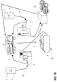
- FIG. 2 shows the construction of an underground waste container 4 in detail. Waste is ground in small particle size by a preparing means 3 and is led via a flow duct system 10 for ground waste through a waste inlet 11 to the storage compartment 13 of the waste container.
- a fluid separation means 12 is arranged between the storage compartment 13 and the fluid compartment 64 in the waste container 4 and provided with an opening system for separating fluid from the ground waste and leading it to the fluid compartment 64.
- the fluid separation means 12 is a wall, made preferably of resin by casting or by a corresponding method and having the shape of the cross-sectional form of the waste container, with a thickness preferably smaller at the bottom than at the top of the waste container 4.
- the opening system formed in the wall comprises openings having substantially a shape of a truncated cone through the wall so that the diameter of the openings is greater on the surface of wall at the side of the storage compartment 13 of the waste container than on the surface of the wall at the side of the fluid compartment 64.
- the waste passing with the fluid forms a plug in the opening, preventing waste from flowing through the opening.
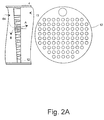
- Separation means 12 of this kind are illustrated in Fig. 2A seen from the side and in a vertical cross-sectional view.
- the openings are larger at the fluid separation means 12 in the bottom part than in the upper part of the waste container 4, wherein the suction used for emptying the storage compartment 13 of the waste container (arrow B in Fig. 2A) cleans substantially the whole opening system of the fluid separation means 12.
- the opening system of the fluid separation means 12 can also be formed by using a plate with narrow horizontal or vertical slits.
- the waste is accumulated in the storage compartment 13 of the waste container, and the fluid rises on the upper surface of the accumulated waste, from where the fluid is separated through the opening system of the fluid separation means 12 and flows further via a sewage outlet 14 into the sewage flow duct system 5.
- the fluid flow between the sewage outlet 14 and the sewage flow duct system 5 as well as the fluid surface level in the fluid compartment 64 can be regulated by a flow control means 15.
- the fill-up sensor 16 gives a signal which is transmitted further via a data transfer means 17, preferably a radio transmitter, to the central control room 18 (Figs. 1A and 1B) or directly to the waste collection unit 6.
- the upper section of the fluid separation means 12 can be provided with an overflow prevention outlet for preventing overflow of the waste container 4.
- the waste container 4 is emptied by removing the lid 19 of the waste outlet on the ground and by inserting a gasket opening means 20 through a gasket 21 so that a suction hose 22 of the waste collection unit 6 (Fig. 5) can be penetrated through the gasket opening means 20 and the waste outlet 23 into the storage compartment 13 of the waste container.
- the gasket 21 prevents the gas contained in the waste container 4 from being spread into the open air during emptying the waste container 4.
- the lid 25 of the aeration inlet on the ground is opened, and the suction apparatus 26 of the waste collection unit is started (Fig. 5).
- the suction hose 22 of the waste collection unit is drawn by the suction effect towards the bottom of the storage compartment 13 of the waste container, whereby the storage compartment of the waste container can be emptied almost completely.
- replacement air is entered through the aeration inlet 27, flowing through the opening system of the fluid separation means 12 and simultaneously cleaning the slits. Replacement air is used to prevent a negative pressure from developing inside the waste container 4 during emptying.
- fluid can be supplied to the waste container via a maintenance duct 28 for facilitating the suction of the waste.
- a fluid tank 29 is supplied preferably with the waste collection unit 6.
- the waste container 4 is provided with a ventilation duct system 30.
- the maintenance duct 28 is normally closed by a lid 31a on the ground and by an intermediate lid 31b.
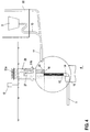
- a second advantageous embodiment of the waste container is shown in Fig. 3.
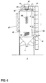
- the waste container 4 is here substantially in a vertical position.
- the waste container 4 can also have a spherical shape, as shown in Fig. 4.
- the waste container is provided with a preparing means 3, a flow duct system 10 for ground waste, a waste inlet 11 and a ventilation duct system 30, as in Fig. 2.
- the fluid separation means 12 is, in this embodiment, preferably a pipe provided with narrow slits for leading the fluid into the sewage outlet 14.
- the waste outlet 23 is placed in the maintenance duct 28.
- the top of the fluid separation means 12 is arranged to extend to the maintenance duct 28, forming an aeration inlet for supplying replacement air to the waste container 4 when it is being emptied.
- this embodiment comprises a fill-up sensor 16 and a data transfer means 17 for informing about the filling up of the container to the central control room 18 or to the waste collection unit 6.
- Figure 5 shows one embodiment of the waste collection unit 6 which is placed e.g. on the chassis of a truck.
- the waste to be collected is sucked by means of a suction hose 22 of the waste collection unit 6 to the waste collection tank 7.
- the suction is controlled by the suction apparatus 26 of the waste collection unit.
- the waste collection unit 6 can comprise a fluid tank 29, from which a fluid pumping device 32 pumps fluid via a fluid supply hose 33 into the waste container 4 during its emptying or washing, if necessary.
- Information on filling up of the waste container is transmitted to the waste collection unit preferably by means of a data transfer means 34 of the waste collection unit.
- the humus production unit 8 comprises a preferably vertical humus tank 40 into which the waste to be composted is led from the waste collection unit via a waste supply inlet 41. Also other kinds of waste, such as wood chips or twigs, can be supplied into the humus production unit through a funnel 42 and a chopper 43. The chopper is operated by a motor 44.
- the humus tank 40 comprises also a fluid outlet system 45 through which excess fluid is removed from the waste to be composted if necessary.
- the fluid outlet system 45 is preferably a vertical, fluid-permeable tube whose lower part is connected with a suitably shaped, impermeable tube. Dewatering can be regulated by a fluid discharge control means 46.
- the fluid to be removed can be advantageously led to the sewage flow duct system 5.
- an aeration duct system 47 can be used for maintaining conditions suitable for composting and, if necessary, for supplying bacteria and other substances accelerating decomposition.
- a gas outlet system 48 connected with the humus tank 40 is required for collection of gas.
- the humus production unit can also be provided with a mixing means 49, preferably a helical coil, which is rotated with an advantageous actuator, such as a motor.
- the finished humus can be removed via the humus outlet 9 at the bottom of the humus tank 40.
- the humus production unit 8 can be provided with a humus fill-up sensor 50 giving a signal when the surface of the humus and waste mass reaches a predetermined level in the humus tank.
- the humus production unit can also be supplied with a moisture sensor 51 indicating the water content of the humus and waste mass as well as a pH sensor 55.
- the degree of decomposition of the waste can be deduced, whereby the necessary corrections can be made in the humus production.
- the humus tank can be provided with a heating means 52 for heating the waste in the humus tank, thus accelerating the decomposition process.
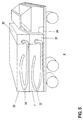
- FIG 7 shows one constructional embodiment of the humus production unit 8 comprising several horizontal tanks.
- the humus production unit 8 consists of three tanks 8a, 8b, 8c, the first one 8a being used as a receiving tank for organic waste; decomposition of the waste is started in this tank.
- the second tank 8b is used as the actual humus production tank, and the third tank 8c is used as a storage tank for final decomposition as well as for temporary storage of finished humus.
- the method is applied by filling the receiving tank 8a with organic waste. When the tank is filled up, the waste is transferred via a receiving tank outlet 53 to a humus production tank 8b, in which the organic waste is decomposed into humus.
- the humus production tank When the humus production tank is filled up, it is emptied via a humus production tank outlet 54 to a storage tank 8c. The finished humus can be removed via a humus outlet 9.
- the system can be applied also by using several tanks, each being in turn used as a receiving, humus production and storage tank.
- the first tank 8a is filled with organic waste until the surface of the waste reaches a predetermined level in the container, whereby the tank is turned into a humus production tank and a second tank 8b is used as a receiving tank for organic waste.
- the humus When the organic waste is turned into humus in the first tank, the humus can be removed from the tank via an outlet, whereby the tank is used again as a receiving tank for organic waste.
- this tank is turned into a humus production tank and the next empty tank is used as a receiving tank for organic waste. Also in this embodiment, it is possible to use a fill-up sensor 50, a moisture sensor 51 and a pH sensor 55.
- the system applying the method of the invention can be also automated e.g. by allotting an identification code to each waste container 4 in the system.
- the identification code of the said container is transmitted to the central control room 18 of the system and possibly to the waste collection unit 6.
- the location, size and quality of waste mass of the waste container 4 can be traced.
- the data is stored in the waste collection unit 6, whereby the route of the waste collection unit 6 can be optimised preferably according to the capacity of the waste collection unit 6.
- the waste collection unit 6 is emptied into the humus production unit 8
- the data on the emptied waste containers is transferred to the central control room.
- the waste collecting and treatment costs can be divided according to individual waste containers, whereby also invoicing can be automated.
- the operation of the humus production unit 8 can be automated, whereby the automation system monitors the measuring results given by the sensors placed in the humus production unit 8.
- the automation system monitors the measuring results given by the sensors placed in the humus production unit 8.
- a humus fill-up sensor indicates that a container is filled up with organic waste
- the actual humus production is started.
- the degree of decomposition is monitored preferably by measurements on the temperature, conductivity, pH value and moisture content.
- a limit value describing the level in finished humus can be defined for each measurement, whereby it can be deduced on the basis of said measuring results whether the humus is finished, so that the decomposition process can be stopped and the humus production unit 8 be emptied.
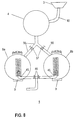
- Figure 8 shows a small-scale system applying the method according to the invention. It comprises a waste container 4, a flow duct system 10 provided also with a preparing means 3, as well as a humus production unit 8 having tanks 8a, 8b, in which the organic waste is transferred for decomposition.
- the waste container 4 and the tanks 8a, 8b of the humus production unit are connected to each other by a suitable flow duct system 56 and guide means 57.
- the ground organic waste coming from the preparing means 3 is transferred via the flow duct system 10 to the waste container 4.
- the organic waste is transferred via the flow duct system 56 into the tanks 8a, 8b of the humus production unit, where the organic waste is decomposed.
- the finished humus can be removed via a humus outlet 9.
- the tanks 8a, 8b are also provided with a fluid outlet system 45, equipped with a suitable opening system and provided for discharging excess fluid from the organic waste to be treated, as well as a mixing means 49.
- the system can also be used in a manner that each tank 8a, 8b is used in turn both as a receiving tank and a humus production tank so that when the receiving tank is filled up, it is turned into a humus production tank and a free tank is turned into a receiving tank.
- the system illustrated in Fig. 8 is best suited for places where relatively large quantities of organic waste is produced. Also in areas of scattered settlement, the system shown in Fig. 8 is an advantageous alternative for the treatment of organic waste.
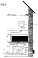
- Figure 9 shows a small-scale system applying the method according to the invention, placed inside a building 63.
- the building can comprise one or several preparing means 3 for organic waste, placed e.g. in connection with the kitchen sink of each apartment.
- the ground organic waste is led from the preparing means 3 via a flow duct system 10 to a waste container 4.
- the waste container 4 includes, as described above in connection with other embodiments, fluid separation means 12 and a sewage outlet 14.
- the organic waste is transferred via the flow duct system 56 to the tank 8 of the humus production unit, where the organic waste is decomposed into humus.
- the finished humus can be removed via a humus outlet 9.
- the figure also shows an aeration duct system 47 facilitating the maintenance of conditions required for decomposition.
- the humus production unit can also be supplied with a mixing means 49 which is rotated with an advantageous actuator, such as a motor, if necessary.
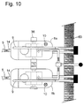
- FIG 10 shows a second small-scale system applying the method according to the invention, placed inside a building 63.
- the difference to the embodiment shown in Fig. 9 is here primarily the fact that each tank 8a, 8b can be used both as a receiving tank for organic waste and as a humus production tank.
- each tank is used in turn as a receiving tank and a humus production tank so that when the receiving tank is filled up, it is turned into a humus production tank and the free tank is turned into a receiving tank, as also presented in connection with the description of Fig. 8.
- Figs. 9 and 10 are heat-insulated and can be placed also outdoors.
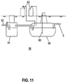
- the system applying the method according to the invention can be equipped with a sewage neutralisation system 58 as illustrated in Fig. 11. Its purpose is to bring the pH value of the fluid separated in the waste container close to neutral, so that the neutralised sewage can be led to a sewage treatment plant.
- the fluid separated in the waste container 4 is led via a sewage flow duct system 5 to a neutralisation tank 59.
- the neutralisation tank 59 is equipped with detector means 60 for measuring the pH value of the sewage. On the basis of data received from the detector means 60, suitable chemicals can be added into the neutralisation tank 59 for neutralisation of the sewage.
- tanks containing neutralising chemicals are indicated by the reference number 63.
- the neutralised sewage is conveyed to a sampling tank 61 where the pH value of the neutralised sewage can be controlled. From the sampling tank 61, the neutralised sewage is conveyed further, either via a neutralised sewage flow duct system 62 to a sewage treatment plant for treatment or, if no such system 62 is available, via filter pipes to the ground.
Landscapes
- Chemical & Material Sciences (AREA)
- Health & Medical Sciences (AREA)
- Life Sciences & Earth Sciences (AREA)
- Molecular Biology (AREA)
- Engineering & Computer Science (AREA)
- Biotechnology (AREA)
- Biochemistry (AREA)
- Chemical Kinetics & Catalysis (AREA)
- General Chemical & Material Sciences (AREA)
- Microbiology (AREA)
- Organic Chemistry (AREA)
- Mechanical Engineering (AREA)
- Processing Of Solid Wastes (AREA)
Claims (10)
- Verfahren zur Behandlung von Abfall durch Verwendung von Abfallbehältern (4), die in regelmässigen Intervallen geleert werden und durch Humus erzeugende Einrichtungen (8), zu welchen der Abfall zugeführt wird, bei welchem Verfahrender Abfall in einem Lagerraum (13) im Abfallbehälter dadurch gesammelt wird, dass er über ein Strömungskanalsystem (10) geleitet,mindestens ein Teil der Flüssigkeit, wie z.B. Wasser, die im Abfall enthalten ist, im Lagerraum (13) durch Verwendung einer Abscheidvorrichtung (12) zur Leitung der Flüssigkeit in eine Fluidkammer (64) abgeschieden wird, undder Inhalt des Lagerraumes (13) des Abfallbehälters in regelmässigen Intervallen entfernt und durch einen Abfallauslass (23) in die Humus erzeugende Einrichtung (8) geleitet wird, in welche beim Entleeren, Ersatzluft durch einen Belüftungseinlass (27) in den Abfallbehälter (4) eingeführt wird,
wobei der Abbau des Abfalls vorzugsweise im Lagerraum (13) des Abfallbehälters (4) anfängt, dadurch gekennzeichnet, dass der Abfallauslass (23) und der Belüftungseinlass (27) auf unterschiedlichen Seiten der Flüssikeitsabscheidvorrichtung angeordnet sind, wobei die beim Entleeren des Abfalls aus dem Lagerraum (13) strömende Luft die Abscheidvorrichtung (12) für die Flüssigkeit reinigt. - Verfahren nach Anspruch 1, dadurch gekennzeichnet, dass der Abfallbehälter (4) als Humus erzeugende Einrichtung verwendbar ist, und die Humus erzeugende Einrichtung auch als Abfallbehälter (4) verwendbar ist.
- Vorrichtung zur Durchführung des Verfahrens nach Anspruch 1, mit mindestens einem Abfallbehälter (4), der in regelmässigen Intervallen zu entleeren ist, und mindestens einer Humus erzeugende Einrichtung (8), wobei der Abfall für Aufnahme im Lagerraum (13) vorgesehen ist, und wobei mindestens der Abfallbehälter (4) eine Flüssigkeitsabscheideinrichtung (12), eine Fluidkammer (64), einen Abwasserauslass (14), einen Abfallauslass (23) und einen Belüftungseinlass (27) umfasst, und/oder die Humus erzeugende Einrichtung (6) ein Flüssigkeitsauslasssystem (45) zum Abscheiden und zur Abgabe von Flüssigkeit aufweist, dadurch gekennzeichnet, dass der Abfallauslass (23) und der Belüftungseinlass (27) an unterschiedlichen Seiten der Flüssikeitsabscheideinrichtung angeordnet sind, wobei die Luftströmung beim Entleeren des Lagerraumes (13) des Abfallbehälters die Abscheidvorrichtung (12) reinigt.
- Vorrichtung nach Anspruch 3, dadurch gekennzeichnet, dass sie eine Abfallsammeleinrichtung einschliesst, in welcher der Lagerraum (13) des Abfallbehälters für Entleerung in regelmässigen Intervallen in die Abfallsammeleinrichtung (6), und die Abfallsammeleinrichtung (6) für eine Entleerung in regelmässigen Intervallen in die Humus erzeugende Einrichtung (8) vorgesehen sind.
- Vorrichtung nach Anspruch 5, dadurch gekennzeichnet, dass der Abfallbehälter (4), die Abfallsammeleinrichtung (6) und die Humus erzeugende Einrichtung (8) als luftdichte Konstruktionen ausgebildet sind.
- Vorrichtung nach Anspruch 3 oder 5, dadurch gekennzeichnet, dass der Abfallbehälter (4), die Abfallsammeleinrichtung (6) und die Humus erzeugende Einrichtung (8) für Aufstellung innerhalb eines Gebäudes vorgesehen sind.
- Vorrichtung nach einem der Ansprüche 3 bis 6, in welcher der Abfallbehälter (4) für eine Entleerung durch einen Saugschlauch (22) vorgesehen ist, dadurch gekennzeichnet, dass der Abfallbehälter (4) eine Saugschlauchführung (24) zur Führung des Saugschlauches (22), vorzugsweise zum Ende des Lagerraumes (13) des Abfallbehälters während der Leerung des Abfallbehälters (4), einschliesst, wobei der Lagerraum (13) des Abfallbehälters fast vollständig geleert werden kann.
- Vorrichtung nach Anspruch 4, dadurch gekennzeichnet, dass die Abfallsammeleinrichtung (6) mit einem im wesentlichen luftdichten Tank (7) und Entleerungseinrichtungen (22,26) ausgestattet ist.
- Abfallbehälter (4), mit einer Flüssgkeitsabscheideinrichtung (12), einem Flüssigkeitsraum (64), einem Abwasserablauf (14), einem Abfallauslass (23) und einem Belüftungseinlass (27), dadurch geennzeichnet, dass der Abfallauslass (23) und der Belüftungseinlass (27) auf unterschiedlichen Seiten der Flüssigkeitsabscheideinrichtung angeordnet sind, wobei die beim Leeren der des Lagerraums (13) strömende Luft des Abfallbehälters die Flüssigkeitsabscheideinrichtung (12) reinigt.
- Vorrichtung nach Anspruch 3 oder 4, oder ein Abfallbehälter (4) nach Anspruch 9, dadurch gekennzeichnet, dass der Lagerraum (13) des Abfallbehälters (4) mit einem Fühler (16) zur Überwachung der Auffüllung des Lagerraumes des Abfallbehälters auf einen vorbestimmten Pegel versehen ist, wobei es an sich bekannt ist, dass der Fühler vorzugsweise ein Radiosendersystem zur Information der Abfallsammeleinrichtung (6) über das Auffüllen des Abfallbehälters (4) und dessen Position aufweist.
Applications Claiming Priority (3)
| Application Number | Priority Date | Filing Date | Title |
|---|---|---|---|
| FI943759 | 1994-08-16 | ||
| FI943759A FI943759A0 (fi) | 1994-08-16 | 1994-08-16 | Foerfarande foer att behandla organogeniska avfall och en i foerfarandet anvaendbar anordning |
| PCT/FI1995/000431 WO1996005154A1 (en) | 1994-08-16 | 1995-08-16 | A method for the treatment of organic waste and an apparatus for use in the method |
Publications (2)
| Publication Number | Publication Date |
|---|---|
| EP0796232A1 EP0796232A1 (de) | 1997-09-24 |
| EP0796232B1 true EP0796232B1 (de) | 2000-03-08 |
Family
ID=8541201
Family Applications (1)
| Application Number | Title | Priority Date | Filing Date |
|---|---|---|---|
| EP95928511A Expired - Lifetime EP0796232B1 (de) | 1994-08-16 | 1995-08-16 | Verfahren zur behandlung von organischen abfällen und vorrichtung zur durchführung des verfahrens |
Country Status (7)
| Country | Link |
|---|---|
| EP (1) | EP0796232B1 (de) |
| AU (1) | AU3224695A (de) |
| DK (1) | DK0796232T3 (de) |
| EE (1) | EE9700037A (de) |
| FI (1) | FI943759A0 (de) |
| RU (1) | RU2136639C1 (de) |
| WO (1) | WO1996005154A1 (de) |
Families Citing this family (7)
| Publication number | Priority date | Publication date | Assignee | Title |
|---|---|---|---|---|
| JP2010259990A (ja) * | 2009-05-01 | 2010-11-18 | Zeotek:Kk | 廃液濾過システム車 |
| CN102583826B (zh) * | 2012-03-01 | 2013-07-17 | 上海莫纳环保科技有限公司 | 资源化集便收集装置 |
| WO2015199891A1 (en) * | 2014-06-27 | 2015-12-30 | Emerson Electric Co. | Food waste storage and treatment system |
| DE102016103078A1 (de) * | 2016-02-22 | 2017-08-24 | Joel Frese | Entsorgungsvorrichtung |
| RU2626160C1 (ru) * | 2016-09-14 | 2017-07-21 | Общество с ограниченной ответственностью "Зеленая планета" | Промышленный способ и устройство переработки органических отходов |
| RU2652100C1 (ru) * | 2017-08-24 | 2018-04-25 | Владимир Александрович Парамошко | Транспортное средство для доставки пакетов с продуктами отправления естественных надобностей на комплекс по производству из них технического спирта и эксклюзивных элементов для сооружения малоэтажного жилья, устойчивого к землетрясениям и ураганам |
| RU2761355C1 (ru) * | 2020-08-03 | 2021-12-07 | Федеральное государственное бюджетное научное учреждение "Федеральный научный центр кормопроизводства и агроэкологии имени В.Р.Вильямса" | Способ утилизации жидкого навоза и устройства для его реализации |
Family Cites Families (4)
| Publication number | Priority date | Publication date | Assignee | Title |
|---|---|---|---|---|
| DE3024813A1 (de) * | 1980-07-01 | 1982-01-28 | Gebrüder Weiss KG, 6340 Dillenburg | Verfahren zum kompostieren von rottegut aus organischen abfaellen und/oder klaerschlamm in zwei verfahrensstufen |
| NO152931C (no) * | 1982-12-14 | 1985-12-18 | Tore Johan Gedde | Fremgangsmaate og anordning for rensing av graavann. |
| DE3605253A1 (de) * | 1986-02-19 | 1987-08-20 | Broesamle Peter | Verfahren und vorrichtung zur aufbereitung von abwasserschlaemmen organischer herkunft sowie verwendung der produkte |
| DE4402976A1 (de) * | 1994-02-01 | 1995-08-17 | Gottfried Dr Hartke | Verfahren zur Behandlung und Entsorgung von Abwasser, insbesondere von Gülle |
-
1994
- 1994-08-16 FI FI943759A patent/FI943759A0/fi not_active Application Discontinuation
-
1995
- 1995-08-16 AU AU32246/95A patent/AU3224695A/en not_active Abandoned
- 1995-08-16 RU RU97103947A patent/RU2136639C1/ru active
- 1995-08-16 EE EE9700037A patent/EE9700037A/xx unknown
- 1995-08-16 DK DK95928511T patent/DK0796232T3/da active
- 1995-08-16 EP EP95928511A patent/EP0796232B1/de not_active Expired - Lifetime
- 1995-08-16 WO PCT/FI1995/000431 patent/WO1996005154A1/en active IP Right Grant
Also Published As
| Publication number | Publication date |
|---|---|
| RU2136639C1 (ru) | 1999-09-10 |
| EP0796232A1 (de) | 1997-09-24 |
| WO1996005154A1 (en) | 1996-02-22 |
| EE9700037A (et) | 1997-10-15 |
| DK0796232T3 (da) | 2000-06-05 |
| AU3224695A (en) | 1996-03-07 |
| FI943759A0 (fi) | 1994-08-16 |
Similar Documents
| Publication | Publication Date | Title |
|---|---|---|
| CN101632996B (zh) | 餐厨垃圾预处理工艺 | |
| AU2007202168A1 (en) | Putrescible organic waste treatment | |
| EP3889123B1 (de) | Heimkomposter | |
| KR101625332B1 (ko) | 음식물류 폐기물 감량화 처리기기를 이용한 쓰레기 자동집하 장치 | |
| US20070029247A1 (en) | Apparatus to separate waste from wastewater | |
| EP0796232B1 (de) | Verfahren zur behandlung von organischen abfällen und vorrichtung zur durchführung des verfahrens | |
| US4341492A (en) | Method for pneumatically handling agglomerative materials | |
| US5568996A (en) | Storage and disposal of organic waste | |
| CN108687119A (zh) | 一种商业厨房模块化餐厨垃圾集中脱水和隔油系统 | |
| EP1684908B1 (de) | Behandlung von fäulnisfähigem organischem abfall | |
| CN118007902A (zh) | 一种住宅建筑的垃圾和污水处理系统 | |
| KR100958817B1 (ko) | 음식물 쓰레기 처리 시스템 | |
| CN208473239U (zh) | 一种楼道餐厨垃圾处理系统 | |
| US3248176A (en) | Apparatus for collecting and treating heterogeneous waste materials | |
| KR101729608B1 (ko) | 음식물 압축기, 음식물 처리 장치, 및 이를 이용한 음식물 처리 방법 | |
| KR101845243B1 (ko) | 필터링 장치, 음식물 처리 장치 및 음식물 처리 방법 | |
| KR20000052828A (ko) | 폐수처리장치 | |
| KR20050012084A (ko) | 집단 주거형 건물의 음식물 쓰레기 일괄 수집 및 처리 장치 | |
| RU71658U1 (ru) | Технологическая система для переработки нефтесодержащих отходов производства | |
| CN208408014U (zh) | 一种商业厨房模块化餐厨垃圾集中脱水和隔油系统 | |
| KR20170070844A (ko) | 음식물 처리 장치 및 음식물 처리 방법 | |
| KR101412169B1 (ko) | 음식물류폐기물의 종량제 수거장치 | |
| CN207026094U (zh) | 一种一体式餐厨垃圾处理系统 | |
| CN220658721U (zh) | 全自动厨余垃圾处理机 | |
| KR200166520Y1 (ko) | 음식물쓰레기처리장치 |
Legal Events
| Date | Code | Title | Description |
|---|---|---|---|
| PUAI | Public reference made under article 153(3) epc to a published international application that has entered the european phase |
Free format text: ORIGINAL CODE: 0009012 |
|
| 17P | Request for examination filed |
Effective date: 19970225 |
|
| AK | Designated contracting states |
Kind code of ref document: A1 Designated state(s): DK SE |
|
| AX | Request for extension of the european patent |
Free format text: LT PAYMENT 970225;LV PAYMENT 970225 |
|
| 17Q | First examination report despatched |
Effective date: 19980916 |
|
| GRAG | Despatch of communication of intention to grant |
Free format text: ORIGINAL CODE: EPIDOS AGRA |
|
| GRAG | Despatch of communication of intention to grant |
Free format text: ORIGINAL CODE: EPIDOS AGRA |
|
| GRAH | Despatch of communication of intention to grant a patent |
Free format text: ORIGINAL CODE: EPIDOS IGRA |
|
| GRAH | Despatch of communication of intention to grant a patent |
Free format text: ORIGINAL CODE: EPIDOS IGRA |
|
| GRAA | (expected) grant |
Free format text: ORIGINAL CODE: 0009210 |
|
| AK | Designated contracting states |
Kind code of ref document: B1 Designated state(s): DK SE |
|
| AX | Request for extension of the european patent |
Free format text: LT PAYMENT 19970225;LV PAYMENT 19970225 |
|
| REG | Reference to a national code |
Ref country code: DK Ref legal event code: T3 |
|
| PGFP | Annual fee paid to national office [announced via postgrant information from national office to epo] |
Ref country code: SE Payment date: 20000719 Year of fee payment: 6 |
|
| EN | Fr: translation not filed | ||
| PGFP | Annual fee paid to national office [announced via postgrant information from national office to epo] |
Ref country code: DK Payment date: 20000825 Year of fee payment: 6 |
|
| PLBE | No opposition filed within time limit |
Free format text: ORIGINAL CODE: 0009261 |
|
| STAA | Information on the status of an ep patent application or granted ep patent |
Free format text: STATUS: NO OPPOSITION FILED WITHIN TIME LIMIT |
|
| 26N | No opposition filed | ||
| PG25 | Lapsed in a contracting state [announced via postgrant information from national office to epo] |
Ref country code: DK Free format text: LAPSE BECAUSE OF NON-PAYMENT OF DUE FEES Effective date: 20010816 |
|
| PG25 | Lapsed in a contracting state [announced via postgrant information from national office to epo] |
Ref country code: SE Free format text: LAPSE BECAUSE OF NON-PAYMENT OF DUE FEES Effective date: 20010817 |
|
| EUG | Se: european patent has lapsed |
Ref document number: 95928511.5 |
|
| REG | Reference to a national code |
Ref country code: DK Ref legal event code: EBP |
|
| LTLA | Lt: lapse of european patent or patent extension |
Effective date: 20020816 |