EP0796123B1 - Transfer set connector with a locking lid and a method of using the same - Google Patents
Transfer set connector with a locking lid and a method of using the same Download PDFInfo
- Publication number
- EP0796123B1 EP0796123B1 EP96925337A EP96925337A EP0796123B1 EP 0796123 B1 EP0796123 B1 EP 0796123B1 EP 96925337 A EP96925337 A EP 96925337A EP 96925337 A EP96925337 A EP 96925337A EP 0796123 B1 EP0796123 B1 EP 0796123B1
- Authority
- EP
- European Patent Office
- Prior art keywords
- component
- tubing
- connector assembly
- length
- lid
- Prior art date
- Legal status (The legal status is an assumption and is not a legal conclusion. Google has not performed a legal analysis and makes no representation as to the accuracy of the status listed.)
- Expired - Lifetime
Links
- 238000000034 method Methods 0.000 title claims description 16
- 239000012530 fluid Substances 0.000 claims abstract description 52
- 238000004891 communication Methods 0.000 claims abstract description 34
- 238000000502 dialysis Methods 0.000 claims abstract description 11
- 238000003780 insertion Methods 0.000 claims description 4
- 230000037431 insertion Effects 0.000 claims description 4
- 230000008878 coupling Effects 0.000 claims description 2
- 238000010168 coupling process Methods 0.000 claims description 2
- 238000005859 coupling reaction Methods 0.000 claims description 2
- 230000013011 mating Effects 0.000 claims description 2
- 230000008901 benefit Effects 0.000 description 7
- 239000000243 solution Substances 0.000 description 6
- 239000008280 blood Substances 0.000 description 4
- 210000004369 blood Anatomy 0.000 description 4
- 238000007789 sealing Methods 0.000 description 3
- 239000000385 dialysis solution Substances 0.000 description 2
- 230000007613 environmental effect Effects 0.000 description 2
- 238000012986 modification Methods 0.000 description 2
- 230000004048 modification Effects 0.000 description 2
- 210000002445 nipple Anatomy 0.000 description 2
- WQZGKKKJIJFFOK-GASJEMHNSA-N Glucose Chemical compound OC[C@H]1OC(O)[C@H](O)[C@@H](O)[C@@H]1O WQZGKKKJIJFFOK-GASJEMHNSA-N 0.000 description 1
- RTAQQCXQSZGOHL-UHFFFAOYSA-N Titanium Chemical compound [Ti] RTAQQCXQSZGOHL-UHFFFAOYSA-N 0.000 description 1
- 230000009471 action Effects 0.000 description 1
- 230000006835 compression Effects 0.000 description 1
- 238000007906 compression Methods 0.000 description 1
- 238000011109 contamination Methods 0.000 description 1
- 239000003814 drug Substances 0.000 description 1
- 239000003792 electrolyte Substances 0.000 description 1
- 230000035764 nutrition Effects 0.000 description 1
- 235000016709 nutrition Nutrition 0.000 description 1
- 230000003204 osmotic effect Effects 0.000 description 1
- 210000003200 peritoneal cavity Anatomy 0.000 description 1
- 229910052719 titanium Inorganic materials 0.000 description 1
- 239000010936 titanium Substances 0.000 description 1
- 230000000007 visual effect Effects 0.000 description 1
- XLYOFNOQVPJJNP-UHFFFAOYSA-N water Substances O XLYOFNOQVPJJNP-UHFFFAOYSA-N 0.000 description 1
Images


Classifications
-
- A—HUMAN NECESSITIES
- A61—MEDICAL OR VETERINARY SCIENCE; HYGIENE
- A61M—DEVICES FOR INTRODUCING MEDIA INTO, OR ONTO, THE BODY; DEVICES FOR TRANSDUCING BODY MEDIA OR FOR TAKING MEDIA FROM THE BODY; DEVICES FOR PRODUCING OR ENDING SLEEP OR STUPOR
- A61M39/00—Tubes, tube connectors, tube couplings, valves, access sites or the like, specially adapted for medical use
- A61M39/20—Closure caps or plugs for connectors or open ends of tubes
-
- A—HUMAN NECESSITIES
- A61—MEDICAL OR VETERINARY SCIENCE; HYGIENE
- A61M—DEVICES FOR INTRODUCING MEDIA INTO, OR ONTO, THE BODY; DEVICES FOR TRANSDUCING BODY MEDIA OR FOR TAKING MEDIA FROM THE BODY; DEVICES FOR PRODUCING OR ENDING SLEEP OR STUPOR
- A61M39/00—Tubes, tube connectors, tube couplings, valves, access sites or the like, specially adapted for medical use
- A61M39/10—Tube connectors; Tube couplings
-
- F—MECHANICAL ENGINEERING; LIGHTING; HEATING; WEAPONS; BLASTING
- F16—ENGINEERING ELEMENTS AND UNITS; GENERAL MEASURES FOR PRODUCING AND MAINTAINING EFFECTIVE FUNCTIONING OF MACHINES OR INSTALLATIONS; THERMAL INSULATION IN GENERAL
- F16L—PIPES; JOINTS OR FITTINGS FOR PIPES; SUPPORTS FOR PIPES, CABLES OR PROTECTIVE TUBING; MEANS FOR THERMAL INSULATION IN GENERAL
- F16L37/00—Couplings of the quick-acting type
- F16L37/08—Couplings of the quick-acting type in which the connection between abutting or axially overlapping ends is maintained by locking members
- F16L37/10—Couplings of the quick-acting type in which the connection between abutting or axially overlapping ends is maintained by locking members using a rotary external sleeve or ring on one part
- F16L37/113—Couplings of the quick-acting type in which the connection between abutting or axially overlapping ends is maintained by locking members using a rotary external sleeve or ring on one part the male part having lugs on its periphery penetrating into the corresponding slots provided in the female part
-
- F—MECHANICAL ENGINEERING; LIGHTING; HEATING; WEAPONS; BLASTING
- F16—ENGINEERING ELEMENTS AND UNITS; GENERAL MEASURES FOR PRODUCING AND MAINTAINING EFFECTIVE FUNCTIONING OF MACHINES OR INSTALLATIONS; THERMAL INSULATION IN GENERAL
- F16L—PIPES; JOINTS OR FITTINGS FOR PIPES; SUPPORTS FOR PIPES, CABLES OR PROTECTIVE TUBING; MEANS FOR THERMAL INSULATION IN GENERAL
- F16L37/00—Couplings of the quick-acting type
- F16L37/08—Couplings of the quick-acting type in which the connection between abutting or axially overlapping ends is maintained by locking members
- F16L37/12—Couplings of the quick-acting type in which the connection between abutting or axially overlapping ends is maintained by locking members using hooks, pawls, or other movable or insertable locking members
- F16L37/1205—Couplings of the quick-acting type in which the connection between abutting or axially overlapping ends is maintained by locking members using hooks, pawls, or other movable or insertable locking members using hooks hinged about an axis placed behind a flange and which act behind the other flange
-
- A—HUMAN NECESSITIES
- A61—MEDICAL OR VETERINARY SCIENCE; HYGIENE
- A61M—DEVICES FOR INTRODUCING MEDIA INTO, OR ONTO, THE BODY; DEVICES FOR TRANSDUCING BODY MEDIA OR FOR TAKING MEDIA FROM THE BODY; DEVICES FOR PRODUCING OR ENDING SLEEP OR STUPOR
- A61M39/00—Tubes, tube connectors, tube couplings, valves, access sites or the like, specially adapted for medical use
- A61M39/10—Tube connectors; Tube couplings
- A61M2039/1027—Quick-acting type connectors
-
- A—HUMAN NECESSITIES
- A61—MEDICAL OR VETERINARY SCIENCE; HYGIENE
- A61M—DEVICES FOR INTRODUCING MEDIA INTO, OR ONTO, THE BODY; DEVICES FOR TRANSDUCING BODY MEDIA OR FOR TAKING MEDIA FROM THE BODY; DEVICES FOR PRODUCING OR ENDING SLEEP OR STUPOR
- A61M39/00—Tubes, tube connectors, tube couplings, valves, access sites or the like, specially adapted for medical use
- A61M39/10—Tube connectors; Tube couplings
- A61M39/14—Tube connectors; Tube couplings for connecting tubes having sealed ends
-
- A—HUMAN NECESSITIES
- A61—MEDICAL OR VETERINARY SCIENCE; HYGIENE
- A61M—DEVICES FOR INTRODUCING MEDIA INTO, OR ONTO, THE BODY; DEVICES FOR TRANSDUCING BODY MEDIA OR FOR TAKING MEDIA FROM THE BODY; DEVICES FOR PRODUCING OR ENDING SLEEP OR STUPOR
- A61M39/00—Tubes, tube connectors, tube couplings, valves, access sites or the like, specially adapted for medical use
- A61M39/22—Valves or arrangement of valves
- A61M39/26—Valves closing automatically on disconnecting the line and opening on reconnection thereof
-
- Y—GENERAL TAGGING OF NEW TECHNOLOGICAL DEVELOPMENTS; GENERAL TAGGING OF CROSS-SECTIONAL TECHNOLOGIES SPANNING OVER SEVERAL SECTIONS OF THE IPC; TECHNICAL SUBJECTS COVERED BY FORMER USPC CROSS-REFERENCE ART COLLECTIONS [XRACs] AND DIGESTS
- Y10—TECHNICAL SUBJECTS COVERED BY FORMER USPC
- Y10S—TECHNICAL SUBJECTS COVERED BY FORMER USPC CROSS-REFERENCE ART COLLECTIONS [XRACs] AND DIGESTS
- Y10S604/00—Surgery
- Y10S604/905—Aseptic connectors or couplings, e.g. frangible, piercable
Definitions
- the present invention generally relates to a connector assembly for connecting a first length of tubing to a second length of tubing. More specifically, the present invention relates to a connector assembly having a locking hinged closure integrally formed with one component of the connector assembly and a cooperating component for opening the locking hinged closure when the two components are connected.
- a cannula or a needle to inject into a patient a solution through the use of a length of tubing which is further connected to a container housing the solution.
- an adaptor or other connector is provided for enabling fluid communication between the container and the patient through the tubing.
- a connector may be provided at a port on the container to connect an end of the length of tubing to the container.
- peritoneal dialysis a dialysis solution is introduced into the peritoneal cavity utilizing a catheter. After a sufficient period of time, an exchange of solutes between the dialysate and the blood is achieved. Fluid removal is achieved by providing a suitable osmotic gradient from the blood to the dialysate to permit water outflow from the blood. The proper acid-base electrolyte and fluid balance to be returned to the blood is achieved, and the dialysis solution is simply drained from the body cavity through the catheter.
- US Patent no. 4,541,658 discloses a quick connector assembly for use with tubular conduits comprising a housing having a check value unit which is operable upon insertion of a conduit.
- One requirement is that the system must provide a quick and a simple disconnection from the system. It is also required that a sterile, contaminant-free environment be maintained after disconnection. Further, the system must provide means for a simple reconnection to the system.
- the present invention provides a connector assembly as claimed in claim 1 and a method for providing fluid communication between a first length of tubing and a second length of tubing as claimed in Claim 24.
- the connector assembly incorporates a locking hinged lid providing sealed disconnection of the assembly.
- a sealed connection is provided by a sealing ring upon connection of the connectors.
- the present invention provides a connector assembly comprising a first component having an opening for establishing fluid communication with a first length of tubing, the first component including a hinged lid on the opposite side of the opening to the tubing covering the opening and integrally formed and selectively displaceable means for removably locking the hinged lid; and a second component having an interior for establishing fluid communication with a second length of tubing, the second component including unlocking means for unlocking the hinged wherein upon insertion of lid the first component into the interior of the second component the unlocking means unlocks the hinged lid and the displaceable means are aligned with the unlocking means to permit fluid communication between the first length of tubing and the second length of tubing.
- the means for locking the lid includes at least one resilient arm.
- the means for locking the lid includes at least one stop capable of locking the lid.
- the connector assembly includes an o-ring to maintain a seal of the lid.
- the means for unlocking the lid includes a resilient key.
- the connector assembly includes a beveled front face formed on the key.
- the connector assembly further comprises a dome portion formed in the second component to allow movement of the key during mating of the components.
- the connector assembly further comprises a tubular member within the interior of the second component, the tubular member extending such that, when the second component mates with the first component, the opening of the first component is in fluid communication with the tubular member.
- the connector assembly includes an o-ring in the interior of the second component.
- the connector assembly further comprises a clamp constructed and arranged to selectively occlude flow through the tubing.
- the clamp may be rotatable about an axis defined along a length of the tubing.
- first component having at least two flexible arms with stops formed thereon for maintaining the hinged lid in a locked and closed position by the stops; and the second component has a means for opening the hinged lid upon connection of the first component to the second component and provide fluid communication between the first length of tubing and the second length of tubing.
- the connector assembly further comprises occluder means for selectively preventing and permitting flow through one of the lengths of tubing.
- the occluder means may be rotatable about an axis defined by the length of tubing.
- the connector assembly further comprises a beveled front end formed in the means for opening the lid; and an opening tab formed in the means for opening the lid.
- the connector assembly further comprises a beveled front end formed in the means for opening the lid, the beveled front end constructed and arranged to spread the flexible arms of the first component.
- the connector assembly further comprises a dome portion formed in the second component to provide clearance for the means for opening during connection of the first component and the second component, while enclosing the space and reducing chance for misuse.
- the first component and the second component are constructed and arranged to prevent misalignment.
- the method for providing fluid communication between a first length of tubing and a second length of tubing connected to a fluid source comprises the steps of: providing a first component having an opening in fluid communication with the first length of tubing wherein the first component has a lid and integrally formed and selectively displaceable means for removably locking the lid; providing a second component in fluid communication with the second length of tubing wherein the second component includes means for locking the lid wherein; removably locking the lid over the opening in the first component; unlocking the opening by coupling the second component to the first component, thereby opening the lid to provide fluid communication between the first and second lengths of tubing.
- the fluid source is a source of dialysate.
- the connector assembly may be used for creating fluid connections in medical procedures.
- the second length of tubing is connected to a source of medical fluid.
- the second length of tubing is connected to a source of dialysate.
- the connector assembly further comprises: a Y-set connector in fluid communication with the second length of tubing; a container of dialysate in fluid communication with the Y-set connector; a second container in fluid communication with the Y-set connector; and a catheter connected to the first length of tubing wherein the catheter is insertable into a patient to perform dialysis.
- Another advantage of the present invention is to provide a system and a method for repeated connection and disconnection of a connector providing fluid communication between a source and a patient.
- Yet another advantage of the present invention is to provide a simple connector that may readily connect and disconnect a first length of tubing from a second length of tubing in a sealed manner.
- a still further advantage of the present invention is to provide a system and a method for connecting and disconnecting a connector between two lengths of tubing which may be easily performed by either a patient or other administrator.
- an advantage of the present invention is to provide a system and a method for connecting and disconnecting a connector between two lengths of tubing requiring few steps.
- Another advantage of the present invention is to provide a compact, ergonomic system for connecting and disconnecting a connector between two lengths of tubing.
- the present invention provides a connector between two lengths of tubing or other conduit for selectively connecting and disconnecting the lengths of tubing.
- fluid communication is provided between a fluid source and a patient. Fluid, however, may be occluded from flowing when connected using an occluder connected with the connector.
- the connector is designed specifically for use in procedures in the medical field, and more specifically for dialysis procedures, it should be noted that the connector can be used in other fields and for other applications.
- Figure 1 illustrates an environmental view of a system employing the connector of the present invention.
- the connector is generally illustrated at 1 and includes a lid lock component 10 and a key component 12.
- the lid lock component 10 is connected to a conduit 14.
- the conduit 14 may be attached via a catheter 15 to a patient.
- the conduit 14 has a twist clamp 16 at one end and a catheter connector 17 at another end.
- the catheter 15 may be connected to the catheter connector 17 via a titanium adapter 18 in a preferred embodiment.
- the Y-set 19 includes two flexible containers 20a, 20b.
- one of the flexible containers for example, the flexible container 20a
- the flexible container 20a is filled with a dialysate and the other flexible container 20b is empty and ready for use as a drain bag.
- the connector 1 of the present invention can readily be used in peritoneal dialysis and CAPD, for example. Other uses for the connector are, of course, possible.
- a fill line 23 is connected to the flexible container 20a, and a drain line 24 is connected to the flexible container 20b. Opposite ends of both the fill line 23 and the drain line 24 are respectively connected to a Y-junction 21.
- the flexible containers 20a and 20b are attached to the key component 12 through the Y-junction 21 and a length of conduit 22 forming a portion of the Y-set 19.
- a clamp 25 may be provided at any point along the length of the fill line 23 to control the flow of the dialysate as desired.
- the clamp 25 may also be connected to the drain line 24 during peritoneal dialysis, if desired.
- the lid lock component 12 of the connector 1 may have the twist clamp 16 connected thereto for occluding fluid flow.
- Figure 2 shows a perspective view of the lid lock component 10 and the key component 12 prior to connection.
- the lid lock component 10 has an exterior dimension designed to fit within an opening 26 of the key component 12 in sliding engagement. Further, the exterior of the lid lock component 10 is designed such that only one orientation of the lid lock component 10 may be received within the opening 26 of the key component 12.
- a longitudinal guide groove 27 is formed in opposite sides of the lid lock component 10.
- the guide grooves 27 cooperatively mate with associated guide rails 28 formed in the key component 12 to strictly direct and align the lid lock component 10 within the opening 26 of the key component 12.
- the cooperating guide grooves 27 and guide rails 28 permit only one permissible operative orientation for the connector 1.
- the lid lock component 10 further includes the twist clamp 16 capable of axial rotation about the conduit 14. In the position illustrated in Figure 2, the conduit 14 (see Figure 1) is pinched closed by a pair of actuators (not shown) within the twist clamp 16. A tab 30 is provided on the twist clamp 16 to aid the user in turning the twist clamp 16, as well as to provide a visual indication of a locked or unlocked condition of the twist clamp 16.
- FIG 2 also shows the various features of the lid lock component 10.
- a pair of flexible arms 31 having integrally formed stops 32 (see Figure 4) and having a channel 33 therebetween are illustrated.
- a side channel 36 which allows for movement of the arms 31 during connection of the components 10,12 of the connector 1 is also provided.
- the key connector 12 includes a flexible longitudinal key 34 having a beveled front end face 35.
- the key component 12 also has a dome 38 to allow movement of the flexible longitudinal key 34 during connection and especially during disconnection (as illustrated in Figure 6) of the connector 1 of the present invention.
- Figure 3 illustrates the connector 1 of the present invention in a connected position. Also, the tab 30 on the twist clamp 16 is shown rotated 90° from the position shown in Figure 2. This indicates to the user that the connector 1 is in a state to allow fluid flow therethrough by means of a port 40 in the twist clamp 16.
- the key component 12 shown in cross-section, is illustrated having the longitudinal key 34 extending within the opening 26 and a tubular member 44 extending substantially parallel to the longitudinal key 34 within the opening 26.
- the lid lock component 10 illustrated in Figure 4 also includes a locking hinged door 50 rotatable about an axle 52.
- the axle 52 allows the door 50, shown in Figure 4 in a locked and closed position, to rotate approximately 90° to an open position shown in Figure 8.
- tubular member 44 has a nipple 46 extending outwardly of the key component 12 to allow for the connection of the conduit 22, for example.
- the longitudinal key 34 forces rotation of the door 50 about the axle 52 as described below.
- the door 50 has a sealing face 54 to provide for a seal against a surface 56 of a tubular channel 58 in an embodiment of the present invention.
- the tubular channel 58 preferably includes, at an opposite end, a barbed nipple 60 to securely connect the conduit 14 thereto, for example.
- the door 50 also seals the tubular channel 58 by providing an o-ring 62 to seal an interior wall 63.
- the lid lock component 10 also includes an adapter 64 intermediately connected to the twist clamp 16.
- the connector 1 is shown immediately prior to connection of the lid lock component 10 to the key component 12 ( Figure 4) and after connection therebetween ( Figure 8).
- the distinction between the connection and disconnection of the lid lock component 10 and the key component 12 is most clearly evident by the position of the door 50.
- the door 50 is substantially parallel to an end face of the lid lock component 10 and sealingly covers the tubular channel 58 to which the tubular member 44 subsequently connects in fluid communication as shown in Figure 8 after the door 50 has rotated 90°.
- the key component 12 is slidingly engaged around the lid lock component 10 allowing the longitudinal key 34 to unlock the door 50 locked by the stops 32 and to force the door 50 to rotate about the axle 52.
- the locked closed door 50 is rotatable about the axle 52.
- the locked closed door 50 has a locking tab 74 which abuts against the stops 32 to hold the door 50 in a locked position until the longitudinal key 34 is used to open the door 50.
- the longitudinal key 34 has an opening tab 76 which has a front face 78.
- the longitudinal key 34 also has an angled face 79 leading to an indented recess 80 to allow for clearance of the opening tab 76 during disconnection of the connector 1.
- the longitudinal key 34 also has a top surface 82 and a flex notch 84 to provide greater flexibility to the longitudinal key 34 when the longitudinal key 34 is retracted in a direction indicated by arrow x as illustrated in Figure 6.
- Figure 6 illustrates how the disconnection of the connector 1 is achieved. The longitudinal key 34 is retracted in the direction of arrow x until the locking tab 74 of the lid 50 is located within the indented recess 80.
- the longitudinal key 34 As the longitudinal key 34 is further retracted, the angled face 79 impinges on the locking tab 74. Continued retraction of the longitudinal key 34 will thus pull the angled face 79 over the top of the locking tab 74.
- the longitudinal key 34 must be flexible; hence, the flex notch 84 is provided to allow the longitudinal key 34 to rise as the angled face 79 climbs over the locking tab 74.
- the dome 38 as shown in Figure 8, provides clearance for the longitudinal key 34 as it rises during retraction. In addition, a lesser amount of flex of the longitudinal key 34 is possible during connection.
- the beveled end face 35 of the longitudinal key 34 contacts and spreads the arms 31 of the lid lock component 10.
- the longitudinal key 34 is flexible, it has sufficient rigidity when in compression to spread the arms 31 to widen the channel 33.
- the longitudinal key 34 proceeds through the channel 33 until it has sufficiently spread open the arms 31 in an outwardly direction as indicated by arrows A, thereby widening the channel 33.
- the front face of the opening tab 76 of the longitudinal key 34 forces the locking tab 74 of the lid 50 through the widened channel 33.
- the longitudinal key 34 sufficiently opens the arms 31 so that the locking tab 74 is able to clear the stops 32 formed in the arms 31.
- the locking tab 74 of the now unlocked lid 50 can then pass through the spread arms 31.
- the door 50 When the key component 12 is connected to the lid lock component 10 as shown in Figure 8, the door 50 is perpendicularly disposed with respect to an end face thereof.
- the opening 26 and the dome 38 are constructed and arranged to allow a clearance for the door 50 to swing therein as shown in Figure 8.
- the lid lock component 10 further includes the twist clamp 16 partially rotatable about an axis parallel to a length of the conduit 14 between the lid lock component 10 and the patient.
- the twist clamp 16 within the twist clamp 16 are the pair of actuators (not shown). The twist clamp 16 rotates about the axis thereby deflecting the position of the actuators in a conduit compressed position and a flowing position.
- Operation of the connector 1 includes insertion of the lid lock component 10 into the key component 12, wherein the longitudinal key 34 spreads the arms 31 to act against the stops 32 locking the door 50, thereby causing the door 50 to open.
- tubular member 44 cooperatively mates with the tubular channel 58 of the lid lock component 10.
- the tubular member 44 is guided adjacent to the opening (see Figure 8) of the lid lock component 10 providing fluid communication through the key component 12 and the lid lock component 10.
- the tubular member 44 of the key component 12 is sealingly engaged to the tubular channel 58 of the lid lock connector 10.
- the tubular member 44 may have a taper 86 for a lead-in to assist in the sealing engagement of the same.
- the tubular member 44 may include an o-ring 88 to maintain the seal therebetween.
Landscapes
- Health & Medical Sciences (AREA)
- Engineering & Computer Science (AREA)
- Heart & Thoracic Surgery (AREA)
- General Engineering & Computer Science (AREA)
- Hematology (AREA)
- Biomedical Technology (AREA)
- Anesthesiology (AREA)
- Life Sciences & Earth Sciences (AREA)
- Animal Behavior & Ethology (AREA)
- General Health & Medical Sciences (AREA)
- Public Health (AREA)
- Veterinary Medicine (AREA)
- Pulmonology (AREA)
- Mechanical Engineering (AREA)
- External Artificial Organs (AREA)
- Infusion, Injection, And Reservoir Apparatuses (AREA)
- Closures For Containers (AREA)
- Quick-Acting Or Multi-Walled Pipe Joints (AREA)
- Separation Using Semi-Permeable Membranes (AREA)
- Coupling Device And Connection With Printed Circuit (AREA)
- Packages (AREA)
- Adornments (AREA)
- Connection Of Plates (AREA)
- Electrotherapy Devices (AREA)
- Orthopedics, Nursing, And Contraception (AREA)
- Protection Of Pipes Against Damage, Friction, And Corrosion (AREA)
Abstract
Description
- The present invention generally relates to a connector assembly for connecting a first length of tubing to a second length of tubing. More specifically, the present invention relates to a connector assembly having a locking hinged closure integrally formed with one component of the connector assembly and a cooperating component for opening the locking hinged closure when the two components are connected.
- In a variety of industries, and for a variety of applications, it is necessary to create and provide a flow path. In many situations, most specifically in the medical industry, it is necessary to create sterile fluid flow paths.
- It is, of course, generally known to provide fluid delivery to a patient for a variety of purposes, such as delivery of a medicament, provide nutrition, and peritoneal dialysis and the like. Such fluid delivery necessitates in many instances the creation of sterile flow paths. Such procedures often require the sterile flow paths to be disconnected and reconnected.
- For example, it is known to use a cannula or a needle to inject into a patient a solution through the use of a length of tubing which is further connected to a container housing the solution. Often, an adaptor or other connector is provided for enabling fluid communication between the container and the patient through the tubing. For example, a connector may be provided at a port on the container to connect an end of the length of tubing to the container.
- It is also well known to provide solutions to a patient, such as for peritoneal dialysis. In peritoneal dialysis, a dialysis solution is introduced into the peritoneal cavity utilizing a catheter. After a sufficient period of time, an exchange of solutes between the dialysate and the blood is achieved. Fluid removal is achieved by providing a suitable osmotic gradient from the blood to the dialysate to permit water outflow from the blood. The proper acid-base electrolyte and fluid balance to be returned to the blood is achieved, and the dialysis solution is simply drained from the body cavity through the catheter.
- US Patent no. 4,541,658 discloses a quick connector assembly for use with tubular conduits comprising a housing having a check value unit which is operable upon insertion of a conduit.
- This procedure is generally repeated three or four times daily for such a patient. Therefore, repeated connections and disconnections are required to be made from the system. Further, such a patient is often interrupted during administration of solution into the body requiring disconnection from the system.
- At least three issues arise with respect to the disconnection and reconnection of a sterile flow path, such as that used for peritoneal dialysis. One requirement is that the system must provide a quick and a simple disconnection from the system. It is also required that a sterile, contaminant-free environment be maintained after disconnection. Further, the system must provide means for a simple reconnection to the system.
- If dismantling of the entire set-up is required, a patient generally will not permit the interruption and will continue receiving the solution ignoring the interruption. On the other hand, if the disconnection and/or reconnection cannot be performed without contaminating the system, the contaminated system components or the entire system must be replaced. In the alternative, the contaminated components of the system must be sterilized before reuse of the system. Again, therefore, the patient will ignore the interruption and continue with the administration of solution from the system. At times, however, interruptions, such as emergencies, will require disconnection from the system.
- A need, therefore, exists for an improved connector system for simplifying disconnection and reconnection of the components of the connector without contamination of the components of the system.
- The present invention provides a connector assembly as claimed in
claim 1 and a method for providing fluid communication between a first length of tubing and a second length of tubing as claimed inClaim 24. The connector assembly incorporates a locking hinged lid providing sealed disconnection of the assembly. A sealed connection is provided by a sealing ring upon connection of the connectors. - To this end, the present invention provides a connector assembly comprising a first component having an opening for establishing fluid communication with a first length of tubing, the first component including a hinged lid on the opposite side of the opening to the tubing covering the opening and integrally formed and selectively displaceable means for removably locking the hinged lid; and a second component having an interior for establishing fluid communication with a second length of tubing, the second component including unlocking means for unlocking the hinged wherein upon insertion of lid the first component into the interior of the second component the unlocking means unlocks the hinged lid and the displaceable means are aligned with the unlocking means to permit fluid communication between the first length of tubing and the second length of tubing.
- In an embodiment, the means for locking the lid includes at least one resilient arm.
- In an embodiment, the means for locking the lid includes at least one stop capable of locking the lid.
- In an embodiment, the connector assembly includes an o-ring to maintain a seal of the lid.
- In an embodiment, the means for unlocking the lid includes a resilient key.
- In an embodiment, the connector assembly includes a beveled front face formed on the key.
- In an embodiment, the connector assembly further comprises a dome portion formed in the second component to allow movement of the key during mating of the components.
- In an embodiment, the connector assembly further comprises a tubular member within the interior of the second component, the tubular member extending such that, when the second component mates with the first component, the opening of the first component is in fluid communication with the tubular member.
- In an embodiment, the connector assembly includes an o-ring in the interior of the second component.
- In another embodiment, the connector assembly further comprises a clamp constructed and arranged to selectively occlude flow through the tubing. The clamp may be rotatable about an axis defined along a length of the tubing.
- In another embodiment the first component having at least two flexible arms with stops formed thereon for maintaining the hinged lid in a locked and closed position by the stops; and the second component has a means for opening the hinged lid upon connection of the first component to the second component and provide fluid communication between the first length of tubing and the second length of tubing.
- In an embodiment, the connector assembly further comprises occluder means for selectively preventing and permitting flow through one of the lengths of tubing. The occluder means may be rotatable about an axis defined by the length of tubing.
- In an embodiment, the connector assembly further comprises a beveled front end formed in the means for opening the lid; and an opening tab formed in the means for opening the lid.
- In an embodiment, the connector assembly further comprises a beveled front end formed in the means for opening the lid, the beveled front end constructed and arranged to spread the flexible arms of the first component.
- In an embodiment, the connector assembly further comprises a dome portion formed in the second component to provide clearance for the means for opening during connection of the first component and the second component, while enclosing the space and reducing chance for misuse.
- In an embodiment, the first component and the second component are constructed and arranged to prevent misalignment.
- The method for providing fluid communication between a first length of tubing and a second length of tubing connected to a fluid source is provided. The method comprises the steps of: providing a first component having an opening in fluid communication with the first length of tubing wherein the first component has a lid and integrally formed and selectively displaceable means for removably locking the lid; providing a second component in fluid communication with the second length of tubing wherein the second component includes means for locking the lid wherein; removably locking the lid over the opening in the first component; unlocking the opening by coupling the second component to the first component, thereby opening the lid to provide fluid communication between the first and second lengths of tubing.
- In an embodiment, the fluid source is a source of dialysate.
- In another embodiment, the connector assembly may be used for creating fluid connections in medical procedures.
- In an embodiment, the second length of tubing is connected to a source of medical fluid.
- In an embodiment, the second length of tubing is connected to a source of dialysate.
- In an embodiment, the connector assembly further comprises: a Y-set connector in fluid communication with the second length of tubing; a container of dialysate in fluid communication with the Y-set connector; a second container in fluid communication with the Y-set connector; and a catheter connected to the first length of tubing wherein the catheter is insertable into a patient to perform dialysis.
- It is, therefore, an advantage of the present invention to provide a system and a method for connecting and disconnecting an assembly providing fluid communication between a source and a patient.
- Another advantage of the present invention is to provide a system and a method for repeated connection and disconnection of a connector providing fluid communication between a source and a patient.
- Yet another advantage of the present invention is to provide a simple connector that may readily connect and disconnect a first length of tubing from a second length of tubing in a sealed manner.
- A still further advantage of the present invention is to provide a system and a method for connecting and disconnecting a connector between two lengths of tubing which may be easily performed by either a patient or other administrator.
- Moreover, an advantage of the present invention is to provide a system and a method for connecting and disconnecting a connector between two lengths of tubing requiring few steps.
- Another advantage of the present invention is to provide a compact, ergonomic system for connecting and disconnecting a connector between two lengths of tubing.
- Additional features and advantages of the present invention are described in, and will be apparent from, the detailed description of the presently preferred embodiments and from the drawings.
-
- Figure 1 illustrates an environmental view of a connector in its disconnected state between a fluid source and a drain bag system at one end and a catheter to be inserted into a patient at another end.
- Figure 2 illustrates an exploded perspective view of an embodiment of the components of the connector in a disconnected position.
- Figure 3 illustrates a perspective view of the connector in a connected position.
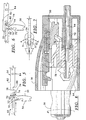
- Figure 4 illustrates a cross-sectional view of a key component and a partially cut-away cross-sectional view of a lid lock component of the connector in a disconnected position.
- Figures 5-7 illustrate detail views of portions of the connector assembly showing successive connection steps and relationships of the key component and the lid lock component.
- Figure 8 illustrates a partially cut-away cross-sectional view of the connector assembly in a connected position.
-
- The present invention provides a connector between two lengths of tubing or other conduit for selectively connecting and disconnecting the lengths of tubing. When connected, fluid communication is provided between a fluid source and a patient. Fluid, however, may be occluded from flowing when connected using an occluder connected with the connector.
- Although the connector is designed specifically for use in procedures in the medical field, and more specifically for dialysis procedures, it should be noted that the connector can be used in other fields and for other applications.
- Referring now to the drawings, Figure 1 illustrates an environmental view of a system employing the connector of the present invention. The connector is generally illustrated at 1 and includes a
lid lock component 10 and akey component 12. As illustrated in Figure 1, thelid lock component 10 is connected to aconduit 14. When in use, theconduit 14 may be attached via acatheter 15 to a patient. Theconduit 14 has atwist clamp 16 at one end and acatheter connector 17 at another end. Thecatheter 15 may be connected to thecatheter connector 17 via atitanium adapter 18 in a preferred embodiment. - The
key component 12, on the other hand, in a preferred embodiment, may be connected to a Y-set generally illustrated at 19. The Y-set 19 includes twoflexible containers flexible container 20a, is filled with a dialysate and the otherflexible container 20b is empty and ready for use as a drain bag. Theconnector 1 of the present invention can readily be used in peritoneal dialysis and CAPD, for example. Other uses for the connector are, of course, possible. - In a preferred embodiment, a
fill line 23 is connected to theflexible container 20a, and adrain line 24 is connected to theflexible container 20b. Opposite ends of both thefill line 23 and thedrain line 24 are respectively connected to a Y-junction 21. Thus, theflexible containers key component 12 through the Y-junction 21 and a length ofconduit 22 forming a portion of the Y-set 19. - A
clamp 25 may be provided at any point along the length of thefill line 23 to control the flow of the dialysate as desired. Theclamp 25 may also be connected to thedrain line 24 during peritoneal dialysis, if desired. In another embodiment, thelid lock component 12 of theconnector 1 may have thetwist clamp 16 connected thereto for occluding fluid flow. - Referring now to Figures 2, 3 and 4, the
connector 1 is illustrated. For example, Figure 2 shows a perspective view of thelid lock component 10 and thekey component 12 prior to connection. Thelid lock component 10 has an exterior dimension designed to fit within anopening 26 of thekey component 12 in sliding engagement. Further, the exterior of thelid lock component 10 is designed such that only one orientation of thelid lock component 10 may be received within theopening 26 of thekey component 12. - To this end, a
longitudinal guide groove 27 is formed in opposite sides of thelid lock component 10. Theguide grooves 27 cooperatively mate with associatedguide rails 28 formed in thekey component 12 to strictly direct and align thelid lock component 10 within theopening 26 of thekey component 12. Thus, the cooperatingguide grooves 27 andguide rails 28 permit only one permissible operative orientation for theconnector 1. - In an embodiment, the
lid lock component 10 further includes thetwist clamp 16 capable of axial rotation about theconduit 14. In the position illustrated in Figure 2, the conduit 14 (see Figure 1) is pinched closed by a pair of actuators (not shown) within thetwist clamp 16. Atab 30 is provided on thetwist clamp 16 to aid the user in turning thetwist clamp 16, as well as to provide a visual indication of a locked or unlocked condition of thetwist clamp 16. - Figure 2 also shows the various features of the
lid lock component 10. For example, a pair offlexible arms 31 having integrally formed stops 32 (see Figure 4) and having achannel 33 therebetween are illustrated. Aside channel 36 which allows for movement of thearms 31 during connection of thecomponents connector 1 is also provided. - Referring now to the
key component 12 of theconnector 1 as shown in Figure 2, thekey connector 12 includes a flexible longitudinal key 34 having a beveledfront end face 35. Thekey component 12 also has adome 38 to allow movement of the flexible longitudinal key 34 during connection and especially during disconnection (as illustrated in Figure 6) of theconnector 1 of the present invention. - Figure 3 illustrates the
connector 1 of the present invention in a connected position. Also, thetab 30 on thetwist clamp 16 is shown rotated 90° from the position shown in Figure 2. This indicates to the user that theconnector 1 is in a state to allow fluid flow therethrough by means of aport 40 in thetwist clamp 16. - Referring now to Figure 4, the
key component 12, shown in cross-section, is illustrated having the longitudinal key 34 extending within theopening 26 and atubular member 44 extending substantially parallel to thelongitudinal key 34 within theopening 26. - The
lid lock component 10 illustrated in Figure 4 also includes a locking hingeddoor 50 rotatable about anaxle 52. Theaxle 52 allows thedoor 50, shown in Figure 4 in a locked and closed position, to rotate approximately 90° to an open position shown in Figure 8. - In addition, the
tubular member 44 has anipple 46 extending outwardly of thekey component 12 to allow for the connection of theconduit 22, for example. Thelongitudinal key 34, during connection of thekey component 12 to thelid lock component 10, forces rotation of thedoor 50 about theaxle 52 as described below. - Referring still to Figure 4, the
door 50 has a sealingface 54 to provide for a seal against asurface 56 of atubular channel 58 in an embodiment of the present invention. Thetubular channel 58 preferably includes, at an opposite end, abarbed nipple 60 to securely connect theconduit 14 thereto, for example. Thedoor 50 also seals thetubular channel 58 by providing an o-ring 62 to seal aninterior wall 63. Thelid lock component 10 also includes anadapter 64 intermediately connected to thetwist clamp 16. - Referring now to Figures 4 and 8, the
connector 1 is shown immediately prior to connection of thelid lock component 10 to the key component 12 (Figure 4) and after connection therebetween (Figure 8). The distinction between the connection and disconnection of thelid lock component 10 and thekey component 12 is most clearly evident by the position of thedoor 50. - In the closed position shown in Figure 4, the
door 50 is substantially parallel to an end face of thelid lock component 10 and sealingly covers thetubular channel 58 to which thetubular member 44 subsequently connects in fluid communication as shown in Figure 8 after thedoor 50 has rotated 90°. When connection of thekey component 12 is desired with thelid lock component 10, thekey component 12 is slidingly engaged around thelid lock component 10 allowing the longitudinal key 34 to unlock thedoor 50 locked by thestops 32 and to force thedoor 50 to rotate about theaxle 52. - Referring now to Figures 5-7, an explanation of the steps involved in opening the
door 50 of thelid lock connector 10 by using thelongitudinal key 34 of thekey component 12 follows. Referring specifically to Figure 5, the lockedclosed door 50 is rotatable about theaxle 52. The locked closeddoor 50 has alocking tab 74 which abuts against thestops 32 to hold thedoor 50 in a locked position until thelongitudinal key 34 is used to open thedoor 50. - Also shown in Figure 5, the
longitudinal key 34 has anopening tab 76 which has afront face 78. The longitudinal key 34 also has an angledface 79 leading to anindented recess 80 to allow for clearance of theopening tab 76 during disconnection of theconnector 1. The longitudinal key 34 also has atop surface 82 and aflex notch 84 to provide greater flexibility to the longitudinal key 34 when thelongitudinal key 34 is retracted in a direction indicated by arrow x as illustrated in Figure 6. Figure 6 illustrates how the disconnection of theconnector 1 is achieved. Thelongitudinal key 34 is retracted in the direction of arrow x until thelocking tab 74 of thelid 50 is located within theindented recess 80. As thelongitudinal key 34 is further retracted, theangled face 79 impinges on thelocking tab 74. Continued retraction of the longitudinal key 34 will thus pull theangled face 79 over the top of thelocking tab 74. However, in order for this action to occur, the longitudinal key 34 must be flexible; hence, theflex notch 84 is provided to allow the longitudinal key 34 to rise as theangled face 79 climbs over the lockingtab 74. Also, thedome 38, as shown in Figure 8, provides clearance for the longitudinal key 34 as it rises during retraction. In addition, a lesser amount of flex of thelongitudinal key 34 is possible during connection. - As further illustrated with reference to Figure 5, the beveled end face 35 of the longitudinal key 34 contacts and spreads the
arms 31 of thelid lock component 10. Although thelongitudinal key 34 is flexible, it has sufficient rigidity when in compression to spread thearms 31 to widen thechannel 33. As shown from the top view of Figure 7, the longitudinal key 34 proceeds through thechannel 33 until it has sufficiently spread open thearms 31 in an outwardly direction as indicated by arrows A, thereby widening thechannel 33. Then, the front face of theopening tab 76 of the longitudinal key 34 forces the lockingtab 74 of thelid 50 through the widenedchannel 33. Thus, the longitudinal key 34 sufficiently opens thearms 31 so that thelocking tab 74 is able to clear thestops 32 formed in thearms 31. Thelocking tab 74 of the now unlockedlid 50 can then pass through thespread arms 31. - When the
key component 12 is connected to thelid lock component 10 as shown in Figure 8, thedoor 50 is perpendicularly disposed with respect to an end face thereof. Theopening 26 and thedome 38 are constructed and arranged to allow a clearance for thedoor 50 to swing therein as shown in Figure 8. After connection of thekey component 12 to thelid lock component 10, fluid communication between the Y-set 19 and the patient can be achieved. - As mentioned above, the
lid lock component 10 further includes thetwist clamp 16 partially rotatable about an axis parallel to a length of theconduit 14 between thelid lock component 10 and the patient. As mentioned above, within thetwist clamp 16 are the pair of actuators (not shown). Thetwist clamp 16 rotates about the axis thereby deflecting the position of the actuators in a conduit compressed position and a flowing position. - Operation of the
connector 1 includes insertion of thelid lock component 10 into thekey component 12, wherein the longitudinal key 34 spreads thearms 31 to act against thestops 32 locking thedoor 50, thereby causing thedoor 50 to open. - Thus, the
tubular member 44 cooperatively mates with thetubular channel 58 of thelid lock component 10. Thetubular member 44 is guided adjacent to the opening (see Figure 8) of thelid lock component 10 providing fluid communication through thekey component 12 and thelid lock component 10. - As the
lid lock component 10 and thekey component 12 are further engaged following the unlocking and the opening of thedoor 50, thetubular member 44 of thekey component 12 is sealingly engaged to thetubular channel 58 of thelid lock connector 10. To this end, thetubular member 44 may have ataper 86 for a lead-in to assist in the sealing engagement of the same. In another embodiment, thetubular member 44 may include an o-ring 88 to maintain the seal therebetween. - It should be understood that various changes and modifications to the presently preferred embodiments described herein will be apparent to those skilled in the art. It is, therefore, intended that such changes and modifications be covered by the appended claims.
Claims (25)
- A connector assembly comprising:a first component (10) having an opening (58) for establishing fluid communication with a first length of tubing (14), the first component (10) including a hinged lid (50) on the opposite side of the opening (58) to the tubing (14) covering the opening (58) and integrally formed, selectively displaceable means (31,32) for removably locking the hinged lid (50); anda second component (12) having an interior (26) for establishing fluid communication with a second length of tubing (22), the second component (12) including unlocking means (34) operable to unlock the hinged lid (50) characterised in that upon insertion of the first component (10) into the interior (26) of the second component (12) the unlocking means (34) unlocks the hinged lid (50) and the displaceable means (31, 32) are aligned with the unlocking means (34) to permit fluid communication between a first length of tubing (14) and a second length of tubing (22).
- A connector assembly as claimed in Claim 1 wherein the first component (10) has an exterior dimension smaller than an exterior dimension of the second component (12) at a point of connection between the first component (10) and the second component (12).
- The connector assembly of Claim 1 or 2 wherein the means (31,32) for locking the hinged lid (50) includes at least one resilient arm (31).
- The connector assembly of Claim 1 or 2 wherein the means (31,32) for locking the hinged lid (50) includes at least one stop (32) capable of locking the hinged lid (50).
- The connector assembly of Claim 1 or 2 wherein the unlocking means (34) includes a resilient key (34).
- The connector assembly of Claim 1 or 2 further comprising a ring (62) to maintain a seal of the hinged lid (50).
- The connector assembly of Claim 5 further comprising a dome portion (38) formed in the second component (12) to allow movement of the key (34) during mating of the first component (10) and the second component (12).
- The connector assembly of Claim 5 further comprising a beveled front face (35) formed on the key (34).
- The connector assembly of Claim 1 or 2 further comprising a tubular member (44) within the interior (26) of the second component (12), the tubular member (44) extending such that, when the second component (12) mates with the first component (10) to open the hinged lid (50) the opening (58) of the first component (10) is in fluid communication with the tubular member (44).
- The connector assembly of Claim 1 or 2 further comprising a ring (88) in the interior (26) of the second component (12).
- The connector assembly of Claim 1 or 2 further comprising a taper (86) in the interior (26) of the second component (12).
- The connector assembly of Claim 1 or 2 further comprising a clamp (16) constructed and arranged to selectively occlude flow through one of the lengths of tubing (14,22).
- The connector assembly of Claim 12 wherein the clamp (16) is rotatable about an axis defined along a length of the said tubing (14,22).
- The connector assembly of Claim 1 wherein the first component (10) has at least two flexible arms (31) with stops (32) formed thereon for maintaining the hinged lid (50) in a locked and closed position by the stops (32); and the unlocking means (34) of the second component (12) is operable to open the hinged lid (50) upon coupling of the first component (10) to the second component (12) to permit fluid communication between the first said length of tubing (14) and the second said length of tubing (22).
- The connector assembly of Claim 14 further comprising occluder means (16) for selectively preventing and permitting flow through one of the said lengths of tubing (14,22).
- The connector assembly of Claim 15 wherein the occluder means (16) is rotatable about an axis defined by the first said length of tubing (14).
- The connector assembly of Claim 14 further comprising:a beveled front end (35) formed in the unlocking means (34) for opening the hinged lid (50); andan opening tab (76) formed in the unlocking means (34) for opening the hinged lid (50).
- The connector assembly of Claim 14 further comprising a beveled front end (35) formed in the unlocking means (34) for opening the hinged lid (50), the beveled front end (35) constructed and arranged for spreading the at least two flexible arms (31) of the first component (10).
- The connector assembly of Claim 14 further comprising a dome portion (38) formed in the second component (12) to provide clearance for the unlocking means (34) during connection of the first component (10) and the second component (12).
- The connector assembly of Claim 14 wherein the first component (10) and the second component (12) are constructed and arranged to prevent misalignment.
- The connector assembly of Claim 1 wherein the second said length of tubing (22) is connectable to a source of medical fluid.
- The connector assembly of Claim 1 wherein the second said length of tubing (22) is connectable to a source of dialysate (20a).
- The connector assembly of Claim 1 further comprising:a Y-set connector (21) in fluid communication with the second said length of tubing (22);a container of dialysate (20a) in fluid communication with the Y-set connector (21);a second container (20b) in fluid communication with the Y-set connector (21); anda catheter (15) connected to the first said length of tubing (14) wherein the catheter (15) is insertable into a patient to perform dialysis.
- A method for providing fluid communication between a first length of tubing (14) and a second length of tubing (22) connected to a fluid source, the method comprising the steps of:providing a first component (10) having an opening (58) in fluid communication with the first length of tubing (14) wherein the first component has a lid (50) and integrally formed, selectively displaceable means (31,32) for removably locking the lid (50);providing a second component (12) having an interior (26) in fluid communication with the second length of tubing (22) wherein the second component (12) includes means (34) for unlocking the lid (50);removably locking the lid (50) over the opening (58) in the first component; characterised byunlocking the opening (58) by inserting the first component (10) into the interior of the second component (12) thereby opening the lid (50) to provide fluid communication between the first (14) and second (22) lengths of tubing.
- The method of Claim 20 wherein the fluid source is a source of dialysate (20a).
Applications Claiming Priority (3)
| Application Number | Priority Date | Filing Date | Title |
|---|---|---|---|
| US510890 | 1995-08-03 | ||
| US08/510,890 US5582600A (en) | 1995-08-03 | 1995-08-03 | Transfer set connector with a locking lid and a method of using the same |
| PCT/US1996/011811 WO1997005921A1 (en) | 1995-08-03 | 1996-07-17 | Transfer set connector with a locking lid and a method of using the same |
Publications (2)
| Publication Number | Publication Date |
|---|---|
| EP0796123A1 EP0796123A1 (en) | 1997-09-24 |
| EP0796123B1 true EP0796123B1 (en) | 2002-10-23 |
Family
ID=24032611
Family Applications (1)
| Application Number | Title | Priority Date | Filing Date |
|---|---|---|---|
| EP96925337A Expired - Lifetime EP0796123B1 (en) | 1995-08-03 | 1996-07-17 | Transfer set connector with a locking lid and a method of using the same |
Country Status (15)
| Country | Link |
|---|---|
| US (1) | US5582600A (en) |
| EP (1) | EP0796123B1 (en) |
| JP (2) | JP3830523B2 (en) |
| KR (1) | KR100400144B1 (en) |
| CN (1) | CN1137737C (en) |
| AT (1) | ATE226463T1 (en) |
| AU (1) | AU707044B2 (en) |
| BR (1) | BR9606565A (en) |
| CA (1) | CA2197549A1 (en) |
| DE (1) | DE69624464T2 (en) |
| DK (1) | DK0796123T3 (en) |
| ES (1) | ES2185788T3 (en) |
| MX (1) | MX9701809A (en) |
| TW (1) | TW305764B (en) |
| WO (1) | WO1997005921A1 (en) |
Cited By (1)
| Publication number | Priority date | Publication date | Assignee | Title |
|---|---|---|---|---|
| CN100589852C (en) * | 2004-12-22 | 2010-02-17 | 泰尔茂株式会社 | Connectors, tubing assemblies, infusion tube assemblies, and medical containers |
Families Citing this family (26)
| Publication number | Priority date | Publication date | Assignee | Title |
|---|---|---|---|---|
| US6228255B1 (en) * | 1998-07-24 | 2001-05-08 | Dialysis Systems, Inc. | Portable water treatment facility |
| US6077259A (en) * | 1998-09-30 | 2000-06-20 | Becton, Dickinson And Company | Contamination resistant connector |
| EP1091614B1 (en) * | 1999-10-06 | 2004-12-15 | Nortel Networks Limited | Switch for optical signals |
| US6251279B1 (en) | 1999-12-09 | 2001-06-26 | Dialysis Systems, Inc. | Heat disinfection of a water supply |
| DE10011724C1 (en) * | 2000-03-10 | 2001-04-26 | Fresenius Medical Care De Gmbh | Connector for sterile packed fluid systems, such as kidney dialysis fluid flow system, comprises connections at both ends, each having inner slides with limit stops |
| DE10352859B3 (en) * | 2003-11-10 | 2005-06-02 | Fresenius Medical Care Deutschland Gmbh | Connector for dialyzer port |
| US20080103484A1 (en) * | 2004-12-22 | 2008-05-01 | Terumo Kabushiki Kaisha | Connector, Tube Assembly, Infusion Tube Set, And Container For Medical Use |
| JP4857853B2 (en) * | 2006-03-28 | 2012-01-18 | ニプロ株式会社 | Transfer tool kit and adapter member |
| JP5265381B2 (en) * | 2006-12-07 | 2013-08-14 | テルモ株式会社 | Infusion tube set |
| US8882700B2 (en) | 2008-05-02 | 2014-11-11 | Baxter International Inc. | Smart patient transfer set for peritoneal dialysis |
| US9348975B2 (en) | 2008-05-02 | 2016-05-24 | Baxter International Inc. | Optimizing therapy outcomes for peritoneal dialysis |
| EP2391404B1 (en) | 2009-01-30 | 2013-01-16 | Baxter International Inc. | Transfer sets for therapy optimization |
| US8753515B2 (en) | 2009-12-05 | 2014-06-17 | Home Dialysis Plus, Ltd. | Dialysis system with ultrafiltration control |
| US8795250B2 (en) | 2010-03-30 | 2014-08-05 | First Quality Baby Products, Llc | Absorbent article having leg cuffs |
| US8501009B2 (en) | 2010-06-07 | 2013-08-06 | State Of Oregon Acting By And Through The State Board Of Higher Education On Behalf Of Oregon State University | Fluid purification system |
| US20130079730A1 (en) * | 2010-06-08 | 2013-03-28 | Theodore J. Mosler | Connector assembly |
| US8777931B2 (en) | 2011-08-19 | 2014-07-15 | Alcon Research, Ltd. | Retractable luer lock fittings |
| CN103957960B (en) | 2011-10-07 | 2016-04-13 | 霍姆透析普拉斯有限公司 | Heat-exchange fluid for dialysis system purifies |
| JP6094829B2 (en) * | 2012-04-13 | 2017-03-15 | 株式会社ジェイ・エム・エス | Male connector with locking mechanism |
| US20150238746A1 (en) * | 2014-02-26 | 2015-08-27 | Baxter Healthcare Sa | Frangible connector closure for tubular connector |
| EP3838308A1 (en) | 2014-04-29 | 2021-06-23 | Outset Medical, Inc. | Dialysis system and methods |
| JP6825210B2 (en) * | 2016-03-02 | 2021-02-03 | 株式会社ジェイ・エム・エス | Puncture needle connector and connecting tube |
| ES2908601T3 (en) | 2016-08-19 | 2022-05-03 | Outset Medical Inc | Peritoneal dialysis system and methods |
| JP2021533881A (en) | 2018-08-23 | 2021-12-09 | アウトセット・メディカル・インコーポレイテッドOutset Medical, Inc. | Dialysis system and method |
| BR112021021836A2 (en) | 2019-04-30 | 2022-01-04 | Outset Medical Inc | Methods for calculating blood pressure, for creating dialysate in a dialysis system, for measuring the percentage of rejection in a dialysis system, for collecting and analyzing blood plasma, for removing gas from an extracorporeal circuit of a dialysis system, for inferring a line pressure in an extracorporeal circuit of a dialysis system, to provide extracorporeal and intracorporeal dialysis therapy, to mount a cartridge-style patient tube set in a dialysis machine, and to prepare a dialysis machine for dialysis therapy , air removal and flow chambers, dialysis system, dialysate dispensing subsystem, single-use microbe/endotoxin filter, dialyzer, device for measuring pressure from a dialysis system, and blood tube set |
| SE545392C2 (en) * | 2021-12-06 | 2023-07-25 | Tada Group Ab | Coupling system for fluid transfer |
Family Cites Families (15)
| Publication number | Priority date | Publication date | Assignee | Title |
|---|---|---|---|---|
| US4541658A (en) * | 1982-03-22 | 1985-09-17 | Proprietary Technology, Inc. | Swivelable quick connector assembly |
| US4752292A (en) * | 1983-01-24 | 1988-06-21 | Icu Medical, Inc. | Medical connector |
| US5344414A (en) * | 1983-01-24 | 1994-09-06 | Icu Medical Inc. | Medical connector |
| US5281206A (en) * | 1983-01-24 | 1994-01-25 | Icu Medical, Inc. | Needle connector with rotatable collar |
| US5330450A (en) * | 1983-01-24 | 1994-07-19 | Icu Medical, Inc. | Medical connector |
| CA1272655A (en) * | 1985-07-31 | 1990-08-14 | Yukihiro Kawano | Connector for plasmapheresis bag |
| US4645494A (en) * | 1985-10-22 | 1987-02-24 | Renal Systems, Inc. | Peritoneal device system |
| DE3605016A1 (en) * | 1986-02-18 | 1987-08-20 | Voss Armaturen | CONNECTING DEVICE WITH ANTI-TWISTING |
| CH672363A5 (en) * | 1986-09-29 | 1989-11-15 | Contempo Products | |
| US4895570A (en) * | 1987-06-05 | 1990-01-23 | Abbott Laboratories | Locking port shroud for peritoneal dialysis tubing connector |
| CA2001732A1 (en) * | 1988-10-31 | 1990-04-30 | Lawrence A. Lynn | Intravenous line coupling device |
| US4950260A (en) * | 1989-11-02 | 1990-08-21 | Safetyject | Medical connector |
| EP0453264A1 (en) * | 1990-04-17 | 1991-10-23 | Lynn, Lawrence A. | Medical connector |
| US5195957A (en) * | 1991-02-01 | 1993-03-23 | Tollini Dennis R | Sterilant cartridge-cap and associated connection |
| US5356396A (en) * | 1992-09-29 | 1994-10-18 | Medical Associates Network Inc. | Infusion apparatus |
-
1995
- 1995-08-03 US US08/510,890 patent/US5582600A/en not_active Expired - Lifetime
-
1996
- 1996-07-17 ES ES96925337T patent/ES2185788T3/en not_active Expired - Lifetime
- 1996-07-17 CA CA002197549A patent/CA2197549A1/en not_active Abandoned
- 1996-07-17 DK DK96925337T patent/DK0796123T3/en active
- 1996-07-17 JP JP50844397A patent/JP3830523B2/en not_active Expired - Lifetime
- 1996-07-17 EP EP96925337A patent/EP0796123B1/en not_active Expired - Lifetime
- 1996-07-17 AU AU65471/96A patent/AU707044B2/en not_active Ceased
- 1996-07-17 AT AT96925337T patent/ATE226463T1/en not_active IP Right Cessation
- 1996-07-17 BR BR9606565A patent/BR9606565A/en not_active IP Right Cessation
- 1996-07-17 CN CNB961908599A patent/CN1137737C/en not_active Expired - Lifetime
- 1996-07-17 KR KR1019970702149A patent/KR100400144B1/en not_active Expired - Fee Related
- 1996-07-17 WO PCT/US1996/011811 patent/WO1997005921A1/en not_active Ceased
- 1996-07-17 DE DE69624464T patent/DE69624464T2/en not_active Expired - Lifetime
- 1996-07-17 MX MX9701809A patent/MX9701809A/en unknown
- 1996-08-03 TW TW085109478A patent/TW305764B/zh not_active IP Right Cessation
-
2006
- 2006-05-11 JP JP2006133140A patent/JP2006255435A/en not_active Withdrawn
Cited By (1)
| Publication number | Priority date | Publication date | Assignee | Title |
|---|---|---|---|---|
| CN100589852C (en) * | 2004-12-22 | 2010-02-17 | 泰尔茂株式会社 | Connectors, tubing assemblies, infusion tube assemblies, and medical containers |
Also Published As
| Publication number | Publication date |
|---|---|
| KR100400144B1 (en) | 2003-12-24 |
| JPH10507396A (en) | 1998-07-21 |
| TW305764B (en) | 1997-05-21 |
| US5582600A (en) | 1996-12-10 |
| JP2006255435A (en) | 2006-09-28 |
| AU6547196A (en) | 1997-03-05 |
| KR970706036A (en) | 1997-11-03 |
| AU707044B2 (en) | 1999-07-01 |
| DE69624464T2 (en) | 2003-06-26 |
| CN1161004A (en) | 1997-10-01 |
| CN1137737C (en) | 2004-02-11 |
| JP3830523B2 (en) | 2006-10-04 |
| WO1997005921A1 (en) | 1997-02-20 |
| EP0796123A1 (en) | 1997-09-24 |
| ES2185788T3 (en) | 2003-05-01 |
| MX9701809A (en) | 1998-04-30 |
| CA2197549A1 (en) | 1997-02-04 |
| ATE226463T1 (en) | 2002-11-15 |
| BR9606565A (en) | 1997-12-30 |
| DK0796123T3 (en) | 2003-02-17 |
| DE69624464D1 (en) | 2002-11-28 |
Similar Documents
| Publication | Publication Date | Title |
|---|---|---|
| US5582600A (en) | Transfer set connector with a locking lid and a method of using the same | |
| US5533996A (en) | Transfer set connector with permanent, integral cam opening closure and a method of using the same | |
| EP0675744B1 (en) | A self-valving connecting device and its use | |
| US11291822B2 (en) | Breakaway medical tubing connector | |
| US4366816A (en) | Combination quick disconnect coupling and fluid cutoff valve | |
| EP3570809B1 (en) | Connector for system for closed transfer of fluids | |
| EP3065812B1 (en) | Connection apparatus for a medical device | |
| US4433973A (en) | Reusable tube connector assembly | |
| EP0041955B1 (en) | Luer lock connection device | |
| US4432759A (en) | Connecting device for medical liquid containers | |
| US7029458B2 (en) | Front-loading syringe adapter for front-loading medical injector | |
| EP0163661B1 (en) | Universal connector | |
| US4418944A (en) | Fluid coupling | |
| JP2007215557A (en) | Detachable extracorporeal circuit | |
| MXPA96001469A (en) | Connector for med tube | |
| AU2019209934B2 (en) | Breakaway medical tubing connector | |
| BR112020014575B1 (en) | APPARATUS IS A METHOD FOR ATTACHING A DETACHABLE IN-LINE CONNECTOR |
Legal Events
| Date | Code | Title | Description |
|---|---|---|---|
| PUAI | Public reference made under article 153(3) epc to a published international application that has entered the european phase |
Free format text: ORIGINAL CODE: 0009012 |
|
| 17P | Request for examination filed |
Effective date: 19970221 |
|
| AK | Designated contracting states |
Kind code of ref document: A1 Designated state(s): AT BE CH DE DK ES FR GB IT LI NL SE |
|
| 17Q | First examination report despatched |
Effective date: 19991122 |
|
| GRAG | Despatch of communication of intention to grant |
Free format text: ORIGINAL CODE: EPIDOS AGRA |
|
| GRAG | Despatch of communication of intention to grant |
Free format text: ORIGINAL CODE: EPIDOS AGRA |
|
| GRAH | Despatch of communication of intention to grant a patent |
Free format text: ORIGINAL CODE: EPIDOS IGRA |
|
| GRAH | Despatch of communication of intention to grant a patent |
Free format text: ORIGINAL CODE: EPIDOS IGRA |
|
| GRAA | (expected) grant |
Free format text: ORIGINAL CODE: 0009210 |
|
| AK | Designated contracting states |
Kind code of ref document: B1 Designated state(s): AT BE CH DE DK ES FR GB IT LI NL SE |
|
| REF | Corresponds to: |
Ref document number: 226463 Country of ref document: AT Date of ref document: 20021115 Kind code of ref document: T |
|
| REG | Reference to a national code |
Ref country code: GB Ref legal event code: FG4D |
|
| REG | Reference to a national code |
Ref country code: CH Ref legal event code: EP |
|
| REG | Reference to a national code |
Ref country code: CH Ref legal event code: NV Representative=s name: KIRKER & CIE SA |
|
| REF | Corresponds to: |
Ref document number: 69624464 Country of ref document: DE Date of ref document: 20021128 |
|
| REG | Reference to a national code |
Ref country code: DK Ref legal event code: T3 |
|
| ET | Fr: translation filed | ||
| REG | Reference to a national code |
Ref country code: ES Ref legal event code: FG2A Ref document number: 2185788 Country of ref document: ES Kind code of ref document: T3 |
|
| PG25 | Lapsed in a contracting state [announced via postgrant information from national office to epo] |
Ref country code: AT Free format text: LAPSE BECAUSE OF NON-PAYMENT OF DUE FEES Effective date: 20030717 |
|
| PG25 | Lapsed in a contracting state [announced via postgrant information from national office to epo] |
Ref country code: ES Free format text: LAPSE BECAUSE OF NON-PAYMENT OF DUE FEES Effective date: 20030718 |
|
| PG25 | Lapsed in a contracting state [announced via postgrant information from national office to epo] |
Ref country code: LI Free format text: LAPSE BECAUSE OF NON-PAYMENT OF DUE FEES Effective date: 20030731 Ref country code: DK Free format text: LAPSE BECAUSE OF NON-PAYMENT OF DUE FEES Effective date: 20030731 Ref country code: CH Free format text: LAPSE BECAUSE OF NON-PAYMENT OF DUE FEES Effective date: 20030731 Ref country code: BE Free format text: LAPSE BECAUSE OF NON-PAYMENT OF DUE FEES Effective date: 20030731 |
|
| PLBE | No opposition filed within time limit |
Free format text: ORIGINAL CODE: 0009261 |
|
| STAA | Information on the status of an ep patent application or granted ep patent |
Free format text: STATUS: NO OPPOSITION FILED WITHIN TIME LIMIT |
|
| 26N | No opposition filed |
Effective date: 20030724 |
|
| BERE | Be: lapsed |
Owner name: *BAXTER INTERNATIONAL INC. Effective date: 20030731 |
|
| PG25 | Lapsed in a contracting state [announced via postgrant information from national office to epo] |
Ref country code: NL Free format text: LAPSE BECAUSE OF NON-PAYMENT OF DUE FEES Effective date: 20040201 |
|
| REG | Reference to a national code |
Ref country code: CH Ref legal event code: PL |
|
| NLV4 | Nl: lapsed or anulled due to non-payment of the annual fee |
Effective date: 20040201 |
|
| REG | Reference to a national code |
Ref country code: DK Ref legal event code: EBP |
|
| REG | Reference to a national code |
Ref country code: ES Ref legal event code: FD2A Effective date: 20030718 |
|
| PG25 | Lapsed in a contracting state [announced via postgrant information from national office to epo] |
Ref country code: IT Free format text: LAPSE BECAUSE OF NON-PAYMENT OF DUE FEES;WARNING: LAPSES OF ITALIAN PATENTS WITH EFFECTIVE DATE BEFORE 2007 MAY HAVE OCCURRED AT ANY TIME BEFORE 2007. THE CORRECT EFFECTIVE DATE MAY BE DIFFERENT FROM THE ONE RECORDED. Effective date: 20050717 |
|
| PGFP | Annual fee paid to national office [announced via postgrant information from national office to epo] |
Ref country code: FR Payment date: 20090717 Year of fee payment: 14 |
|
| REG | Reference to a national code |
Ref country code: FR Ref legal event code: ST Effective date: 20110331 |
|
| PG25 | Lapsed in a contracting state [announced via postgrant information from national office to epo] |
Ref country code: FR Free format text: LAPSE BECAUSE OF NON-PAYMENT OF DUE FEES Effective date: 20100802 |
|
| PGFP | Annual fee paid to national office [announced via postgrant information from national office to epo] |
Ref country code: SE Payment date: 20130729 Year of fee payment: 18 |
|
| PGFP | Annual fee paid to national office [announced via postgrant information from national office to epo] |
Ref country code: DE Payment date: 20140729 Year of fee payment: 19 |
|
| PGFP | Annual fee paid to national office [announced via postgrant information from national office to epo] |
Ref country code: GB Payment date: 20140729 Year of fee payment: 19 |
|
| REG | Reference to a national code |
Ref country code: SE Ref legal event code: EUG |
|
| PG25 | Lapsed in a contracting state [announced via postgrant information from national office to epo] |
Ref country code: SE Free format text: LAPSE BECAUSE OF NON-PAYMENT OF DUE FEES Effective date: 20140718 |
|
| REG | Reference to a national code |
Ref country code: DE Ref legal event code: R119 Ref document number: 69624464 Country of ref document: DE |
|
| GBPC | Gb: european patent ceased through non-payment of renewal fee |
Effective date: 20150717 |
|
| PG25 | Lapsed in a contracting state [announced via postgrant information from national office to epo] |
Ref country code: GB Free format text: LAPSE BECAUSE OF NON-PAYMENT OF DUE FEES Effective date: 20150717 Ref country code: DE Free format text: LAPSE BECAUSE OF NON-PAYMENT OF DUE FEES Effective date: 20160202 |