EP0795803A2 - Method and apparatus for holographically recording an essentially periodic pattern - Google Patents
Method and apparatus for holographically recording an essentially periodic pattern Download PDFInfo
- Publication number
- EP0795803A2 EP0795803A2 EP97103956A EP97103956A EP0795803A2 EP 0795803 A2 EP0795803 A2 EP 0795803A2 EP 97103956 A EP97103956 A EP 97103956A EP 97103956 A EP97103956 A EP 97103956A EP 0795803 A2 EP0795803 A2 EP 0795803A2
- Authority
- EP
- European Patent Office
- Prior art keywords
- substrate
- periodic
- mask pattern
- hologram
- object beam
- Prior art date
- Legal status (The legal status is an assumption and is not a legal conclusion. Google has not performed a legal analysis and makes no representation as to the accuracy of the status listed.)
- Withdrawn
Links
- 230000000737 periodic effect Effects 0.000 title claims abstract description 42
- 238000000034 method Methods 0.000 title claims abstract description 35
- 239000000758 substrate Substances 0.000 claims abstract description 90
- 238000004519 manufacturing process Methods 0.000 claims description 8
- 238000011161 development Methods 0.000 claims description 4
- 238000000025 interference lithography Methods 0.000 abstract description 4
- 238000005286 illumination Methods 0.000 description 6
- XUIMIQQOPSSXEZ-UHFFFAOYSA-N Silicon Chemical compound [Si] XUIMIQQOPSSXEZ-UHFFFAOYSA-N 0.000 description 2
- 230000001427 coherent effect Effects 0.000 description 2
- 238000000609 electron-beam lithography Methods 0.000 description 2
- 239000000463 material Substances 0.000 description 2
- 230000001902 propagating effect Effects 0.000 description 2
- 238000000926 separation method Methods 0.000 description 2
- 229910052710 silicon Inorganic materials 0.000 description 2
- 239000010703 silicon Substances 0.000 description 2
- 230000015572 biosynthetic process Effects 0.000 description 1
- 239000012530 fluid Substances 0.000 description 1
- 238000001093 holography Methods 0.000 description 1
- 238000001459 lithography Methods 0.000 description 1
- 238000005259 measurement Methods 0.000 description 1
- 238000004377 microelectronic Methods 0.000 description 1
- 238000012986 modification Methods 0.000 description 1
- 230000004048 modification Effects 0.000 description 1
- 230000003287 optical effect Effects 0.000 description 1
- 238000012545 processing Methods 0.000 description 1
Images


Classifications
-
- G—PHYSICS
- G03—PHOTOGRAPHY; CINEMATOGRAPHY; ANALOGOUS TECHNIQUES USING WAVES OTHER THAN OPTICAL WAVES; ELECTROGRAPHY; HOLOGRAPHY
- G03H—HOLOGRAPHIC PROCESSES OR APPARATUS
- G03H1/00—Holographic processes or apparatus using light, infrared or ultraviolet waves for obtaining holograms or for obtaining an image from them; Details peculiar thereto
- G03H1/26—Processes or apparatus specially adapted to produce multiple sub- holograms or to obtain images from them, e.g. multicolour technique
-
- G—PHYSICS
- G03—PHOTOGRAPHY; CINEMATOGRAPHY; ANALOGOUS TECHNIQUES USING WAVES OTHER THAN OPTICAL WAVES; ELECTROGRAPHY; HOLOGRAPHY
- G03H—HOLOGRAPHIC PROCESSES OR APPARATUS
- G03H1/00—Holographic processes or apparatus using light, infrared or ultraviolet waves for obtaining holograms or for obtaining an image from them; Details peculiar thereto
- G03H1/02—Details of features involved during the holographic process; Replication of holograms without interference recording
-
- G—PHYSICS
- G03—PHOTOGRAPHY; CINEMATOGRAPHY; ANALOGOUS TECHNIQUES USING WAVES OTHER THAN OPTICAL WAVES; ELECTROGRAPHY; HOLOGRAPHY
- G03F—PHOTOMECHANICAL PRODUCTION OF TEXTURED OR PATTERNED SURFACES, e.g. FOR PRINTING, FOR PROCESSING OF SEMICONDUCTOR DEVICES; MATERIALS THEREFOR; ORIGINALS THEREFOR; APPARATUS SPECIALLY ADAPTED THEREFOR
- G03F7/00—Photomechanical, e.g. photolithographic, production of textured or patterned surfaces, e.g. printing surfaces; Materials therefor, e.g. comprising photoresists; Apparatus specially adapted therefor
- G03F7/70—Microphotolithographic exposure; Apparatus therefor
- G03F7/70408—Interferometric lithography; Holographic lithography; Self-imaging lithography, e.g. utilizing the Talbot effect
-
- G—PHYSICS
- G03—PHOTOGRAPHY; CINEMATOGRAPHY; ANALOGOUS TECHNIQUES USING WAVES OTHER THAN OPTICAL WAVES; ELECTROGRAPHY; HOLOGRAPHY
- G03H—HOLOGRAPHIC PROCESSES OR APPARATUS
- G03H1/00—Holographic processes or apparatus using light, infrared or ultraviolet waves for obtaining holograms or for obtaining an image from them; Details peculiar thereto
- G03H1/04—Processes or apparatus for producing holograms
- G03H1/0402—Recording geometries or arrangements
- G03H1/0408—Total internal reflection [TIR] holograms, e.g. edge lit or substrate mode holograms
-
- G—PHYSICS
- G03—PHOTOGRAPHY; CINEMATOGRAPHY; ANALOGOUS TECHNIQUES USING WAVES OTHER THAN OPTICAL WAVES; ELECTROGRAPHY; HOLOGRAPHY
- G03H—HOLOGRAPHIC PROCESSES OR APPARATUS
- G03H1/00—Holographic processes or apparatus using light, infrared or ultraviolet waves for obtaining holograms or for obtaining an image from them; Details peculiar thereto
- G03H1/04—Processes or apparatus for producing holograms
- G03H1/0465—Particular recording light; Beam shape or geometry
-
- G—PHYSICS
- G03—PHOTOGRAPHY; CINEMATOGRAPHY; ANALOGOUS TECHNIQUES USING WAVES OTHER THAN OPTICAL WAVES; ELECTROGRAPHY; HOLOGRAPHY
- G03H—HOLOGRAPHIC PROCESSES OR APPARATUS
- G03H1/00—Holographic processes or apparatus using light, infrared or ultraviolet waves for obtaining holograms or for obtaining an image from them; Details peculiar thereto
- G03H1/04—Processes or apparatus for producing holograms
- G03H1/0402—Recording geometries or arrangements
- G03H2001/0415—Recording geometries or arrangements for recording reflection holograms
-
- G—PHYSICS
- G03—PHOTOGRAPHY; CINEMATOGRAPHY; ANALOGOUS TECHNIQUES USING WAVES OTHER THAN OPTICAL WAVES; ELECTROGRAPHY; HOLOGRAPHY
- G03H—HOLOGRAPHIC PROCESSES OR APPARATUS
- G03H1/00—Holographic processes or apparatus using light, infrared or ultraviolet waves for obtaining holograms or for obtaining an image from them; Details peculiar thereto
- G03H1/04—Processes or apparatus for producing holograms
- G03H1/18—Particular processing of hologram record carriers, e.g. for obtaining blazed holograms
- G03H2001/186—Swelling or shrinking the holographic record or compensation thereof, e.g. for controlling the reconstructed wavelength
Definitions
- the present invention relates to a method and an apparatus for holographically recording periodic or quasi-periodic features of a mask in a holographic recording layer.
- US 4,857,425 discloses a method for the manufacture of integrated circuits using Total Internal Reflection (TIR) holography.
- TIR Total Internal Reflection
- the disclosed TIR holographic technique is characterized in that a first substrate bearing a holographic recording layer is disposed on the hypotenuse face of a prism and a second substrate containing e.g. an integrated circuit pattern is arranged in proximity to the first substrate.
- the distance between the first and the second substrate is usually about 100 microns.
- the pattern of the integrated circuit is holographically recorded in the holographic recording layer of the first substrate by illuminating said photosensitive layer with an object and a reference beam of mutually coherent light, the object beam passing through the mask window and being incident on the holographic layer at 90 degree, and the reference beam being projected through one of the shorter faces of the prism at such an angle that the light is totally internally reflected off the photosensitive layer/air interface.
- the interference between the object and the reference beams is recorded in the photosensitive layer which after proper development and fixation presents the hologram.
- the hologram is again contacted with the prism face and the second substrate is replaced e.g. by a silicon wafer bearing a photosensitive layer. Thereafter a so-called reconstruction beam is directed through the prism in the exactly reversed direction to the reference beam used for the hologram recording.
- the hologram often is turned by 180 o so that the reference beam functions as reconstruction beam.
- the reconstruction beam produces a positive image of the circuit pattern in the photosensitive layer of the silicon wafer.
- DFB-lasers Distributed FeedBack Lasers
- Their fabrication requires the formation of a fine period grating in the order of approximately 0.2 ⁇ m on a substrate material.
- DFB-lasers use electron-beam lithography to "write" the grating lines. This is a slow process and therefore very expensive and not commercially attractive for large production quantities.
- a general problem of high resolution lithography is the restricted depth of focus of the imaged patterns.
- holographic lithography it is therefore necessary that the separation between hologram and wafer in the hologram reconstruction step is the same as the separation between recording layer and mask in the hologram recording step.
- Means are therefore provided which allow measurement and adjustment between the mask and the recording layer during hologram recording and between hologram and wafer during hologram reproduction step (see e.g. US 4,857,425 issued to Philipps).
- An object of the present invention is to overcome the shortcomings of the prior art and, in particular, to provide a method and an apparatus for holographically recording an essentially periodic pattern of features with still better resolution in a holographic recording layer.
- the method comprises the following steps:
- the resolution capability by TIR holographic lithography can be significantly improved provided that the mask pattern comprises essentially periodic or quasi-periodic features.
- the theoretical limit to the smallest period which can be recorded can be as small as ⁇ ⁇ /2 in contrast to the conventional holographic technique where the smallest theoretically attainable period is ⁇ .
- the depth of focus is significantly increased in comparison with a conventional TIR hologram recording arrangement in which the object beam is normal to the plane of the mask.
- a quasi-periodic mask pattern is a pattern having a limited bandwidth of spatial frequencies (e.g. +/- 10% of the average spatial frequency) in contrast to a pattern having a precise or discrete period.
- Such a quasi-periodic mask pattern may comprise a sequence of grating segments each with a precise (and the same) period but offset with respect to each other by some fraction of the grating period. This is commonly the case for DFB Lasers.
- the object beam is directed to the first substrate at an angle such that the normal to the plane of the first substrate essentially bisects the directions of the zero and first diffraction orders.
- the structures which will be formed upon illumination of the hologram in the photosensitive layer on a wafer or the like will have essentially perpendicular sidewalls with respect to the plane of the wafer. This can be of importance for subsequent processing of the wafer.
- the plane of incidence of the object beam on the second substrate or mask contains the vector describing the direction of the periodicity, i.e. if the periodic features are lines in a grating, the object beam is essentially orthogonal to the grating lines. In this way the contrast of the optical interference pattern recorded in the holographic layer can be maximised.
- the second substrate is replaced by another substrate bearing a mask pattern containing periodic or quasi-periodic features in a second direction a hologram containing features of different periods and in different directions can be produced.
- the pattern recorded in these holograms can be subsequently reconstructed onto a photosensitive layer on a single substrate thereby composing a complex two-dimensional pattern, for instance a microcircuit application.
- the planes of incidence of the object beams contain the direction of periodicity of the respective mask patterns.
- the above methods allow the simultaneous or consecutive recording of two-dimensional structures without re-arranging the object beams.
- the plane of incidence of the reference beam is in the plane of incidence of the object beam.
- the method performs also well when the plane of incidence of the reference beam is not in the plane of the object beam.
- the reconstruction of the holograms can be done by optically contacting the hologram - after development and fixation of the same - again with the prism face, replacing the substrate bearing the mask pattern by another substrate having a photosensitive layer and then directing the reference beam - with respect to the beam direction in the hologram recording step - in the reversed direction through the prism.
- the invention relates also to a holographic recording system for working the method.
- the system comprises
- the above apparatus allows the recording of substantially periodic structures with higher resolution than conventional apparati in the field of holographic lithography.
- Further preferred embodiments of the invention are described in the sub-claims. These include e.g. means for varying the angle of incidence of the object beam so that the system can be easily adapted to the recording of features of different periods.
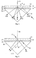
- a conventional holographic recording system comprises a prism 21, a substrate 19 bearing a holographic recording layer 17 and a second substrate 13 containing a grating pattern 14.
- the second substrate 13 is arranged parallel and in proximity to the first substrate 19.
- a coherent light beam 11 or object beam is sent through the second substrate 13 whereby the light beam 11 is diffracted at the grating pattern 14.
- a reference beam 15 is directed through the prism 21 to the first substrate 19 at such an angle that it is reflected off the holographic recording layer/air interface.
- the interference of the diffracted orders generated by the grating pattern 14 with the reference beam 15 is recorded in the holographic layer 17 and thereby forms a hologram.
- the light beam 11 of wavelength ⁇ passing through the grating 13 of a period d is diffracted and produces a zero order, two first orders, (+1,-1) and two second orders (+2,-2).
- the number of diffraction orders depends on the ratio of ⁇ /d (wavelength/grating period).
- Figure 2 illustrates a novel arrangement, particularly useful for recording periodic or quasi-periodic features.
- the object beam 11 is arranged such that it illuminates the mask pattern at an angle ⁇ with respect to the normal 23 to the substrate planes and such that the plane of incidence of the beam 11 contains the direction of periodicity of the grating pattern 14.
- the angle of incidence ⁇ of the object beam 11 is arranged such that the first diffraction order (-1) and the zero order (undiffracted light) are symmetrically disposed either side of the normal 23 to the mask plane, i.e. the normal 23 bisects the directions of the zero and first diffraction orders.
- the period of the features to be recorded should be in the following range: ⁇ /2 ⁇ d ⁇ 3 ⁇ /2
- the new method and apparatus exhibits higher resolution for recording periodic structures.
- the depth of focus of the image at reconstruction becomes infinite for an infinite grating structure.
- the depth of focus of the reconstructed image will be a maximum in the middle and will decrease towards the edges of the image. Nonetheless, by proper choice of the various parameters ( size of the mask pattern, wavelength, angle of incidence of the light beams and resolution of the features to be printed) the specification on the reconstruction apparatus can be relaxed resulting in much lower investment costs and a simpler manufacture procedure.
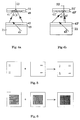
- the hologram recording system of Fig. 3 may be used.
- the main difference with respect to known hologram recording systems is that the object beam is directed towards the plane of the mask at an angle ⁇ to the normal to the mask substrate plane such that the plane of incidence of the object beam 11 contains the direction of periodicity of the periodic pattern 14.
- the recording system comprises a light source 25, usually a laser source, whose emitting light beam 27 is split by a beam splitter 29 into an object beam 11 and a reference beam 15.
- the beams 11,15 are both expanded by an appropriate expansion optics 31.
- the expansion optics usually comprises an expansion lens and a collimating lens. By these means well collimated light beams 11 and 15 are formed.
- the light beam 27 may alternatively be expanded before the beam splitter 29 so that just one expansion optics 31 is needed.
- the object beam 11 is directed by a mirror 37 to the mask substrate 13 so that it illuminates the mask pattern 14 at an off-axis angle ⁇ .
- the reference beam 15 is deflected by mirror 39 so that it is directed through the hypotenuse face of the prism 21 to the holographic recording layer 17 at an angle of approximately 45 o such that the beam is totally internally reflected off the recording layer/air interface.
- the mask pattern 14 is arranged parallel and at a distance s above the recording layer 17 using piezoelectric transducers 33.
- Figure 4a illustrates schematically the difference in the patterns 41 printed from holograms 43 where during hologram recording the zero and first diffraction orders were symmetrical to the normal to the holographic layer bearing prism face (Fig. 4a) and asymmetric thereto (Fig. 4b).
- a positive image of the mask pattern is reconstructed in the photosensitive layer 49 on a substrate 51 to form a structure or pattern 41 after development.
- the two reconstructed diffraction orders emanating from the hologram 41 are essentially symmetrical to the normal 23. Accordingly, the sidewalls of the three-dimensional structures 41 printed into the photosensitive layer 49 are essentially perpendicular to plane of substrate 51.
- Figure 4b shows the structures 41' printed into the photosensitive layer 49' from a hologram 43' where during hologram recording the angle of incidence of the zero and first diffraction orders were different ( ⁇ 1 and ⁇ 2 , respectively).
- the printed structure 41' has substantially oblique sidewalls with respect to the substrate plane. For the manufacture of microelectronic devices this is undesirable.
- Fig. 5 shows how a hologram recording periodic structures in two different directions in the xy-plane can be manufactured from two masks, each having a periodic structure in one specific direction.
- Fig. 6 illustrates the manufacture of a two-dimensional grating structure from a single mask having a periodic structure in one distinct direction. After a first holographic recording the mask pattern 13 and the object beam are rotated by 90 o and then a second hologram is recorded so that a two-dimensional grating structure is produced.
- FIG. 7 A possible prism shape which allows the use of more than one set of object and reference beams is shown in Fig. 7.
- the prism 21' has two beam entry faces 53 (just one is shown in the cross sectional view), each for one reference beam.
- the prism can be used for the simultaneous recording of features in two different directions.
- Another embodiment of a possible prism shape is shown in Fig. 8.
- the hologram recording of a substantially periodic pattern can be conducted as follows (see e.g. Fig. 3): First a substrate 19 coated with an appropriate holographic recording layer 17 is arranged on one of the prism faces. A fluid with the same refractive index as the prism and the substrate material is applied between the substrate 19 and the prism 21 so that the reference beam 15 can pass from the prism 21 to the substrate 19 without being reflected. A second substrate 13 containing a mask pattern 14 is then arranged parallel and in proximity to the first substrate 19.
- the mask pattern 14 of the second substrate 13 can be produced by any of the known lithographic methods e.g. electron beam lithography.
- a light beam preferably from a laser source, is split by a beam splitter 29 into an object beam 11 and a reference beam 15.
- the beams 11,15 are expanded and collimated by one or more expansion optics 31 in a known manner.
- the reference beam 15 is directed through one of the prism faces such that it is totally reflected from the holographic recording layer/air interface of the substrate.
- the object beam 11 is directed to the first substrate 19 at an off-axis angle.
- the object beam passing the mask pattern 13 is thereby diffracted.
- the angle of incidence is chosen according to the wavelength of the light used and the prevailing period in the mask pattern 14.
- the object and reference beams 11,15 interfere with each other in the photosensitive layer 17 thereby forming a hologram of the mask pattern 14.
- the first substrate 19 may be rotated or replaced by another substrate having a second mask pattern of a same or different period and a second illumination can take place. After all the illumination steps have been completed the holographic layer 17 is fixed.
- a hologram 43 (Fig. 4a)
- the hologram substrate 19 is again contacted to the prism face and the substrate containing the mask pattern is replaced by a substrate 51 coated with a photosensitive layer 49.
- a reconstruction light beam 45 is directed through one of the prism faces in exactly the reverse direction to the reference beam direction. Light diffracted by the hologram thereby reconstructs a positive image of the mask pattern in the photosensitive layer 49.
- the above described method and apparatus for performing the method is particularly useful for forming holograms from substantially periodic or quasi-periodic mask patterns.
Abstract
The present invention relates to a method and an apparatus for holographically recording periodic or quasi-periodic features of a mask (14) in a holographic recording layer (17). In holographic lithography the object beam (11) is directed to the first substrate (19) bearing a holographic recording layer (17) such that it passes the mask substrate (13) and interferes with a reference beam (15) in the recording layer (17) to form a hologram of the mask pattern (14). According to the new method the object beam (11) is directed to the second substrate (13) at an off-axis angle and the wavelength used and/or the angle of incidence of the object beam (11) are selected according to the period of the features to be recorded such that essentially just the zero and one of the first diffraction orders are present for forming the hologram.
Description
- The present invention relates to a method and an apparatus for holographically recording periodic or quasi-periodic features of a mask in a holographic recording layer.
- US 4,857,425 discloses a method for the manufacture of integrated circuits using Total Internal Reflection (TIR) holography. The disclosed TIR holographic technique is characterized in that a first substrate bearing a holographic recording layer is disposed on the hypotenuse face of a prism and a second substrate containing e.g. an integrated circuit pattern is arranged in proximity to the first substrate. The distance between the first and the second substrate is usually about 100 microns. In a first step the pattern of the integrated circuit is holographically recorded in the holographic recording layer of the first substrate by illuminating said photosensitive layer with an object and a reference beam of mutually coherent light, the object beam passing through the mask window and being incident on the holographic layer at 90 degree, and the reference beam being projected through one of the shorter faces of the prism at such an angle that the light is totally internally reflected off the photosensitive layer/air interface. The interference between the object and the reference beams is recorded in the photosensitive layer which after proper development and fixation presents the hologram.
- For the reconstruction the hologram is again contacted with the prism face and the second substrate is replaced e.g. by a silicon wafer bearing a photosensitive layer. Thereafter a so-called reconstruction beam is directed through the prism in the exactly reversed direction to the reference beam used for the hologram recording. For this purpose, in practice, the hologram often is turned by 180o so that the reference beam functions as reconstruction beam. The reconstruction beam produces a positive image of the circuit pattern in the photosensitive layer of the silicon wafer.
- Although the holographic system of Philips allows recording of features in the submicron level the attainable practical resolution in some cases is still not high enough for certain applications, e.g. for manufacturing so-called Distributed FeedBack Lasers (DFB-lasers). Their fabrication requires the formation of a fine period grating in the order of approximately 0.2 µm on a substrate material. At present the manufacturers of DFB-lasers use electron-beam lithography to "write" the grating lines. This is a slow process and therefore very expensive and not commercially attractive for large production quantities.
- A general problem of high resolution lithography is the restricted depth of focus of the imaged patterns. In holographic lithography it is therefore necessary that the separation between hologram and wafer in the hologram reconstruction step is the same as the separation between recording layer and mask in the hologram recording step. Means are therefore provided which allow measurement and adjustment between the mask and the recording layer during hologram recording and between hologram and wafer during hologram reproduction step (see e.g. US 4,857,425 issued to Philipps).
- An object of the present invention is to overcome the shortcomings of the prior art and, in particular, to provide a method and an apparatus for holographically recording an essentially periodic pattern of features with still better resolution in a holographic recording layer.
- According to the invention the method comprises the following steps:
- optically contacting a first substrate bearing a holographic recording layer to one face of a prism;
- disposing a second substrate bearing a first mask pattern parallel and in proximity to the first substrate, the mask pattern containing periodic or quasi-periodic features in a first direction;
- splitting and expanding or vice versa a light beam of a certain wavelength to generate an object beam and a reference beam
- directing the reference beam to one of the remaining prism faces such that the reference light beam is totally internally reflected off the holographic recording layer/air interface and
- directing the object beam to the first substrate such that it passes the mask pattern and interferes with the reference beam in the holographic recording layer to form a hologram of the mask pattern, wherein the object beam is directed to the second substrate at an off-axis angle and the wavelength used and/or the angle of incidence of the object beam are selected according to the period of the features to be recorded such that essentially just the zero and one of the first diffraction orders are present for forming the hologram.
- It has been found that by using such off-axis object beam illumination the resolution capability by TIR holographic lithography can be significantly improved provided that the mask pattern comprises essentially periodic or quasi-periodic features. The theoretical limit to the smallest period which can be recorded can be as small as ≅ λ /2 in contrast to the conventional holographic technique where the smallest theoretically attainable period is λ. In addition to this resolution advantage, since there are only two propagating diffraction orders of light, the depth of focus is significantly increased in comparison with a conventional TIR hologram recording arrangement in which the object beam is normal to the plane of the mask.
- A quasi-periodic mask pattern is a pattern having a limited bandwidth of spatial frequencies (e.g. +/- 10% of the average spatial frequency) in contrast to a pattern having a precise or discrete period. Such a quasi-periodic mask pattern may comprise a sequence of grating segments each with a precise (and the same) period but offset with respect to each other by some fraction of the grating period. This is commonly the case for DFB Lasers.
- Advantageously, the object beam is directed to the first substrate at an angle such that the normal to the plane of the first substrate essentially bisects the directions of the zero and first diffraction orders. In this manner the structures which will be formed upon illumination of the hologram in the photosensitive layer on a wafer or the like, will have essentially perpendicular sidewalls with respect to the plane of the wafer. This can be of importance for subsequent processing of the wafer.
- According to an advantageous embodiment the plane of incidence of the object beam on the second substrate or mask contains the vector describing the direction of the periodicity, i.e. if the periodic features are lines in a grating, the object beam is essentially orthogonal to the grating lines. In this way the contrast of the optical interference pattern recorded in the holographic layer can be maximised.
- Different modifications of the inventive method are feasible. For instance, after recording a hologram according to the above method it is possible to rotate the second substrate containing the mask pattern with respect to the first substrate and to rotate the object beam such that the plane of incidence of the object beam again contains the direction of the periodicity and to record the mask pattern of the second substrate in the holographic recording layer a second time. By this procedure high-resolution grating structures in different directions may be recorded and subsequently printed. Instead of rotating the pattern containing second substrate, the first substrate bearing the holographic recording layer may be rotated.
- If the second substrate is replaced by another substrate bearing a mask pattern containing periodic or quasi-periodic features in a second direction a hologram containing features of different periods and in different directions can be produced.
- It is also possible to record the same or different mask patterns in two or more different holographic recording layers on two or more different first substrates for forming two or more holograms. The pattern recorded in these holograms can be subsequently reconstructed onto a photosensitive layer on a single substrate thereby composing a complex two-dimensional pattern, for instance a microcircuit application.
- According to a particularly advantageous embodiment of the method the second substrate containing a mask pattern having periodic or quasi-periodic features in at least two essentially different directions is used and wherein the mask patterns are recorded in the holographic recording layer either by
- simultaneously illuminating the periodic features with at least two sets of object and reference beams, each set of object and reference beams emanating from a separate light source, where the object beams are at off-axis angles such that essentially the zero and one of the first diffraction order are generated by the respective periodic features to be recorded in the hologram
- first illuminating the periodic features in the first direction with first object and reference beams where the object beam is at an off-axis angle such that essentially the zero and one of the first diffraction order are generated by the respective periodic features to be recorded in the hologram; and then illuminating the periodic features of the second direction with second object and reference beams where the object beam is at an off-axis angle such that essentially the zero and one of the first diffraction order are generated by the second periodic features.
- Preferably the planes of incidence of the object beams contain the direction of periodicity of the respective mask patterns.
- The above methods allow the simultaneous or consecutive recording of two-dimensional structures without re-arranging the object beams. Preferably, also the plane of incidence of the reference beam is in the plane of incidence of the object beam. However, the method performs also well when the plane of incidence of the reference beam is not in the plane of the object beam.
- The reconstruction of the holograms can be done by optically contacting the hologram - after development and fixation of the same - again with the prism face, replacing the substrate bearing the mask pattern by another substrate having a photosensitive layer and then directing the reference beam - with respect to the beam direction in the hologram recording step - in the reversed direction through the prism.
- The invention relates also to a holographic recording system for working the method. The system comprises
- a prism
- a first substrate bearing a holographic recording layer and being optically contacted to one of the prism faces
- a second substrate being disposed parallel and in proximity to the first substrate, the second substrate bearing a mask pattern containing periodic or quasi-periodic features in a first direction,
- at least one light source emitting light with a certain wavelength
- a beam splitting and expansion optics for generating
- an object beam and
- a reference beam
- means for directing the reference beam to one of the remaining prism faces such that the reference beam is totally reflected off the holographic recording layer/air interface and
- means for directing the object beam to the first substrate such that it passes the mask pattern and interferes with the reference beam in the holographic recording layer to form a hologram of the mask pattern wherein the object beam directing means are arranged such that the object beam is directed to the second substrate at an off-axis angle and wherein the wavelength used and/or the angle of incidence of the object beam are selected according to the period of the features to be recorded such that essentially just the zero and one of the first diffraction orders are present for forming the hologram.
- The above apparatus allows the recording of substantially periodic structures with higher resolution than conventional apparati in the field of holographic lithography. Further preferred embodiments of the invention are described in the sub-claims. These include e.g. means for varying the angle of incidence of the object beam so that the system can be easily adapted to the recording of features of different periods.
- A particularly advantageous embodiment comprises
- a second light source and means for generating second object and second reference beams independent of the first object and first reference beams; and
- a prism allowing directing the first and the second reference beams to the first substrate at such an angle that the reference beams are reflected off the holographic recording layer/air interface.
- The invention is hereinafter described with reference to the drawings, in which
- Figure 1
- schematically illustrates hologram recording in a conventional TIR hologram recording system exemplified by the diffraction of a object beam by a mask pattern constituting a one-dimensional grating of a period d;
- Figure 2
- illustrates hologram recording in a hologram recording system according to the invention with an off-axis object beam;
- Figure 3
- shows schematically an apparatus for performing the invention;
- Figure 4
- illustrates schematically the problems arising if zero and first order diffracted light are not symmetrical with respect to the normal to the plane of the mask;
- Figure 5
- principally shows how different periodic patterns of two substrates can be transferred in one hologram;
- Figure 6
- principally shows how two-dimensional grating structures can be manufactured from a single pattern; and
- Figure 7
- shows a possible prism shape in a cross-sectional view which allows the use of two sets of object and reference beams;
- Figure 8
- another embodiment of a prism which allows the use of two sets of object and reference beams in a perspective view.
- According to Fig. 1 a conventional holographic recording system comprises a
prism 21, asubstrate 19 bearing aholographic recording layer 17 and asecond substrate 13 containing agrating pattern 14. Thesecond substrate 13 is arranged parallel and in proximity to thefirst substrate 19. For hologram recording acoherent light beam 11 or object beam is sent through thesecond substrate 13 whereby thelight beam 11 is diffracted at thegrating pattern 14. Areference beam 15 is directed through theprism 21 to thefirst substrate 19 at such an angle that it is reflected off the holographic recording layer/air interface. The interference of the diffracted orders generated by thegrating pattern 14 with thereference beam 15 is recorded in theholographic layer 17 and thereby forms a hologram. - In this example, the
light beam 11 of wavelength λ passing through the grating 13 of a period d is diffracted and produces a zero order, two first orders, (+1,-1) and two second orders (+2,-2). In the general case, the number of diffraction orders depends on the ratio of λ/d (wavelength/grating period). - It is well known that the angle θn of the nth diffraction order is governed by the general formula:

- From this formula it is evident that first order diffracted light will only be present if

- Accordingly, with the known system of figure 1 the smallest period which can theoretically be recorded is equal to the wavelength λ of the light used.
- Figure 2 illustrates a novel arrangement, particularly useful for recording periodic or quasi-periodic features. In contrast to the known holographic recording system of Fig. 1 the
object beam 11 is arranged such that it illuminates the mask pattern at an angle θ with respect to the normal 23 to the substrate planes and such that the plane of incidence of thebeam 11 contains the direction of periodicity of thegrating pattern 14. In the preferred embodiment the angle of incidence θ of theobject beam 11 is arranged such that the first diffraction order (-1) and the zero order (undiffracted light) are symmetrically disposed either side of the normal 23 to the mask plane, i.e. the normal 23 bisects the directions of the zero and first diffraction orders. With this arrangement the angle of incidence is related to the wavelength and the period of the mask pattern by
- Accordingly, the theoretical limit of the smallest period which can be recorded is

- If the period of the pattern is too large (

- Thus, in practice the period of the features to be recorded should be in the following range:

- In the above range the new method and apparatus exhibits higher resolution for recording periodic structures.
- It is to be noted that, if there are only two propagating orders of light, the depth of focus of the image at reconstruction becomes infinite for an infinite grating structure. For finite patterns the depth of focus of the reconstructed image will be a maximum in the middle and will decrease towards the edges of the image. Nonetheless, by proper choice of the various parameters ( size of the mask pattern, wavelength, angle of incidence of the light beams and resolution of the features to be printed) the specification on the reconstruction apparatus can be relaxed resulting in much lower investment costs and a simpler manufacture procedure.
- For recording a substantially periodic pattern the hologram recording system of Fig. 3 may be used. The main difference with respect to known hologram recording systems is that the object beam is directed towards the plane of the mask at an angle θ to the normal to the mask substrate plane such that the plane of incidence of the
object beam 11 contains the direction of periodicity of theperiodic pattern 14. The recording system comprises alight source 25, usually a laser source, whose emittinglight beam 27 is split by abeam splitter 29 into anobject beam 11 and areference beam 15. Thebeams appropriate expansion optics 31. The expansion optics usually comprises an expansion lens and a collimating lens. By these means well collimated light beams 11 and 15 are formed. It is to be noted that thelight beam 27 may alternatively be expanded before thebeam splitter 29 so that just oneexpansion optics 31 is needed. - The
object beam 11 is directed by amirror 37 to themask substrate 13 so that it illuminates themask pattern 14 at an off-axis angle θ. Thereference beam 15 is deflected bymirror 39 so that it is directed through the hypotenuse face of theprism 21 to theholographic recording layer 17 at an angle of approximately 45o such that the beam is totally internally reflected off the recording layer/air interface. Themask pattern 14 is arranged parallel and at a distance s above therecording layer 17 usingpiezoelectric transducers 33. - Figure 4a illustrates schematically the difference in the
patterns 41 printed fromholograms 43 where during hologram recording the zero and first diffraction orders were symmetrical to the normal to the holographic layer bearing prism face (Fig. 4a) and asymmetric thereto (Fig. 4b). - Upon illumination of the
hologram 43 by a reconstruction beam 45 a positive image of the mask pattern is reconstructed in thephotosensitive layer 49 on asubstrate 51 to form a structure orpattern 41 after development. As can be seen from the schematic drawing Fig. 4a the two reconstructed diffraction orders emanating from thehologram 41 are essentially symmetrical to the normal 23. Accordingly, the sidewalls of the three-dimensional structures 41 printed into thephotosensitive layer 49 are essentially perpendicular to plane ofsubstrate 51. Figure 4b, in contrast, shows the structures 41' printed into the photosensitive layer 49' from a hologram 43' where during hologram recording the angle of incidence of the zero and first diffraction orders were different (Φ1 and Φ2, respectively). The printed structure 41' has substantially oblique sidewalls with respect to the substrate plane. For the manufacture of microelectronic devices this is undesirable. - Fig. 5 shows how a hologram recording periodic structures in two different directions in the xy-plane can be manufactured from two masks, each having a periodic structure in one specific direction.
- Fig. 6 illustrates the manufacture of a two-dimensional grating structure from a single mask having a periodic structure in one distinct direction. After a first holographic recording the
mask pattern 13 and the object beam are rotated by 90o and then a second hologram is recorded so that a two-dimensional grating structure is produced. - A possible prism shape which allows the use of more than one set of object and reference beams is shown in Fig. 7. The prism 21' has two beam entry faces 53 (just one is shown in the cross sectional view), each for one reference beam. The prism can be used for the simultaneous recording of features in two different directions. Another embodiment of a possible prism shape is shown in Fig. 8.
- The hologram recording of a substantially periodic pattern can be conducted as follows (see e.g. Fig. 3): First a
substrate 19 coated with an appropriateholographic recording layer 17 is arranged on one of the prism faces. A fluid with the same refractive index as the prism and the substrate material is applied between thesubstrate 19 and theprism 21 so that thereference beam 15 can pass from theprism 21 to thesubstrate 19 without being reflected. Asecond substrate 13 containing amask pattern 14 is then arranged parallel and in proximity to thefirst substrate 19. Themask pattern 14 of thesecond substrate 13 can be produced by any of the known lithographic methods e.g. electron beam lithography. - For hologram recording a light beam, preferably from a laser source, is split by a
beam splitter 29 into anobject beam 11 and areference beam 15. Thebeams more expansion optics 31 in a known manner. - The
reference beam 15 is directed through one of the prism faces such that it is totally reflected from the holographic recording layer/air interface of the substrate. Theobject beam 11 is directed to thefirst substrate 19 at an off-axis angle. The object beam passing themask pattern 13 is thereby diffracted. The angle of incidence is chosen according to the wavelength of the light used and the prevailing period in themask pattern 14. - During illumination the object and
reference beams photosensitive layer 17 thereby forming a hologram of themask pattern 14. Thereafter thefirst substrate 19 may be rotated or replaced by another substrate having a second mask pattern of a same or different period and a second illumination can take place. After all the illumination steps have been completed theholographic layer 17 is fixed. - To reconstruct a hologram 43 (Fig. 4a), the
hologram substrate 19 is again contacted to the prism face and the substrate containing the mask pattern is replaced by asubstrate 51 coated with aphotosensitive layer 49. Areconstruction light beam 45 is directed through one of the prism faces in exactly the reverse direction to the reference beam direction. Light diffracted by the hologram thereby reconstructs a positive image of the mask pattern in thephotosensitive layer 49. - The above described method and apparatus for performing the method is particularly useful for forming holograms from substantially periodic or quasi-periodic mask patterns.
Claims (16)
- Method of holographically recording periodic or quasi-periodic features of a mask pattern in a holographic recording layer comprising:- optically contacting a first substrate (19) bearing a holographic recording layer (17) to one face of a prism (21);- disposing a second substrate (13) bearing a first mask pattern parallel and in proximity to the first substrate (19), the mask pattern( 14) containing periodic or quasi-periodic features in a first direction;- splitting and expanding or vice versa a light beam (27) of a certain wavelength to generate an object beam (11) and a reference beam (15)- directing the reference beam (15) to one of the remaining prism faces such that the reference light beam (15) is totally internally reflected off the holographic recording layer/air interface and- directing the object beam (11) to the first substrate (19) such that it passes the mask pattern( 14) and interferes with the reference beam (15) in the holographic recording layer (17) to form a hologram of the mask pattern( 14), wherein the object beam (11) is directed to the second substrate (13) at an off-axis angle and the wavelength used and/or the angle of incidence of the object beam (11) are selected according to the period of the features to be recorded such that essentially just the zero and one of the first diffraction orders are present for forming the hologram.
- Method according to claim 1 wherein the object beam (11) is directed to the first substrate (19) at an angle such that the normal to the plane of the first substrate (19) essentially bisects the directions of the zero and first diffraction orders.
- Method according to claim 1 or 2 wherein the plane of incidence of the object beam (11) on the second substrate (13) or mask (14) contains the direction of the periodic features.
- Method according to any one of claims 1 to 3 comprising the additional steps of- rotating the second substrate (13) with respect to the first substrate (19);- rotating the object beam (11) such that the plane of incidence of the object beam (11) again contains the direction of the periodic features; and- recording the mask pattern( 14) of the second substrate (13) in the holographic recording layer (17) a second time.
- Method according to any one of claims 1 to 3 comprising- replacing the second substrate (13) after recording the same by another substrate (13) or mask pattern (14) containing periodic or quasi-periodic features in a second direction;- rotating or arranging the object beam (11) in such a way that the plane of incidence of the object beam (11) contains the periodic features of the second direction; and- recording said second features in the holographic recording layer (17).
- Method according to claim 4 or 5 wherein the steps of claim 4 or 5 are repeated.
- Method according to any one of claims 1 to 3 wherein the same or different mask patterns ( 14) are recorded in two or more different holographic recording layers (17) on two or more different first substrates (19) for forming two or more holograms.
- Method according to one of the claims 1 to 3 wherein a second substrate (13) containing a mask pattern( 14) having periodic or quasi-periodic features in at least two essentially different directions is used and wherein the mask patterns (14) are recorded in the holographic recording layer (17) either by- simultaneously illuminating the periodic features with at least two sets of object (11) and reference (15) beams, each set of object (11) and reference (15) beams emanating from a separate light source (25), where the object beams (11) are at off-axis angles such that essentially the zero and one of the first diffraction order are generated by the respective periodic features to be recorded in the hologramor by- first illuminating the periodic features in the first direction with first object (11) and reference (15) beams where the object beam (11) is at an off-axis angle such that essentially the zero and one of the first diffraction order are generated by the respective periodic features to be recorded in the hologram; and then illuminating the periodic features of the second direction with second object 11) and reference (15) beams where the object beam (11) is at an off-axis angle such that essentially the zero and one of the first diffraction order are generated by the second periodic features.
- Method according to one of the claims 1 to 8 wherein the direction of the reference beam (15) is preferably in the plane of the object beam (11).
- Method according to one of the claims 1 to 9 wherein the wavelength of the light used is in the following range:

- Method according to one of the claims 1 to 10 wherein after development and fixation of the holographic layer (17) the hologram is again contacted with the prism face and then reconstructed by replacing the substrate (13) bearing the mask pattern (14) by another substrate (51) having a photosensitive layer (49) and directing the reference beam (45) - with respect to the beam direction in the hologram recording step - in the reversed direction through the prism (21).
- Total Internal Reflection (TIR) hologram recording system for lithographic purposes, in particular for recording periodic or quasi-periodic features of a mask pattern in a holographic recording layer, comprising- a prism (21)- a first substrate (19) bearing a holographic recording layer (17) and being optically contacted to one of the prism faces- a second substrate (13) being disposed parallel and in proximity to the first substrate (19), the second substrate (13) bearing a mask pattern( 14) containing periodic or quasi-periodic features in a first direction,- at least one light source (25) emitting light (27) with a certain wavelength- a beam splitting (29) and expansion optics (31) for generating- an object beam (11) and- a reference beam (15)- means (39) for directing the reference beam (15) to one of the remaining prism faces such that the reference beam (15) is totally reflected off the holographic recording layer/air interface and- means (37) for directing the object beam (11) to the first substrate (19) such that it passes the mask pattern( 14) and interferes with the reference beam (15) in the holographic recording layer (17) to form a hologram of the mask pattern( 14) wherein the object beam (11) directing means are arranged such that the object beam (11) is directed to the second substrate (13) at an off-axis angle and wherein the wavelength used and/or the angle of incidence of the object beam (11) are selected according to the period of the features to be recorded such that essentially just the zero and one of the first diffraction orders are present for forming the hologram.
- System according to claim 12 wherein the direction of the object beam (11) with respect to the first substrate (19) is at an angle such that the normal to the plane of the first substrate (19) essentially bisects the directions of the zero and first diffraction orders.
- System according to claim 12 or 13 wherein means are provided for varying the angle of incidence of the object beam (11).
- System according to one of the claims 11 to 13 further comprising- a second light source and means for generating second object and second reference beams independent of the first object (11) and first reference beams (15); and- a prism (21) allowing directing the first and the second reference beams to the first substrate (19) at such an angle that the reference beams are reflected off the holographic recording layer/air interface.
- Use of the method according to one of the claims 1 to 11 for manufacturing a DFB-laser.
Applications Claiming Priority (2)
| Application Number | Priority Date | Filing Date | Title |
|---|---|---|---|
| GB9605235A GB2311144B (en) | 1996-03-12 | 1996-03-12 | Method and apparatus for holographically recording an essentially periodic pattern |
| GB9605235 | 1996-03-12 |
Publications (2)
| Publication Number | Publication Date |
|---|---|
| EP0795803A2 true EP0795803A2 (en) | 1997-09-17 |
| EP0795803A3 EP0795803A3 (en) | 1998-02-11 |
Family
ID=10790284
Family Applications (1)
| Application Number | Title | Priority Date | Filing Date |
|---|---|---|---|
| EP97103956A Withdrawn EP0795803A3 (en) | 1996-03-12 | 1997-03-10 | Method and apparatus for holographically recording an essentially periodic pattern |
Country Status (5)
| Country | Link |
|---|---|
| US (1) | US6226110B1 (en) |
| EP (1) | EP0795803A3 (en) |
| JP (1) | JPH1020750A (en) |
| KR (1) | KR970066764A (en) |
| GB (1) | GB2311144B (en) |
Cited By (2)
| Publication number | Priority date | Publication date | Assignee | Title |
|---|---|---|---|---|
| WO2004010222A2 (en) * | 2002-07-22 | 2004-01-29 | Forschungszentrum Karlsruhe Gmbh | Method for the production of photoresist structures |
| CN111726952A (en) * | 2020-06-22 | 2020-09-29 | Oppo广东移动通信有限公司 | Shell assembly, preparation method thereof and electronic equipment |
Families Citing this family (10)
| Publication number | Priority date | Publication date | Assignee | Title |
|---|---|---|---|---|
| DE19752094C1 (en) | 1997-11-25 | 1999-07-15 | Bundesrep Deutschland | Method for determining at least one piece of diagnostic information from signal patterns of medical sensor systems |
| US6806982B2 (en) * | 2001-11-30 | 2004-10-19 | Zebra Imaging, Inc. | Pulsed-laser systems and methods for producing holographic stereograms |
| JP2003297718A (en) * | 2002-03-29 | 2003-10-17 | Seiko Epson Corp | Fine hole forming method, semiconductor device manufacturing method, semiconductor device, display, and electronic apparatus |
| US7651521B2 (en) * | 2004-03-02 | 2010-01-26 | Cardiomind, Inc. | Corewire actuated delivery system with fixed distal stent-carrying extension |
| US20060232838A1 (en) * | 2005-04-13 | 2006-10-19 | Holoptics Sa | Method and apparatus for forming a surface-relief hologram mask |
| KR101506949B1 (en) * | 2007-04-16 | 2015-03-30 | 노쓰 캐롤라이나 스테이트 유니버시티 | Methods of fabricating liquid crystal polarization gratings on substrates and related devices |
| JP2010165423A (en) * | 2009-01-16 | 2010-07-29 | Sony Corp | Record and reproducing method, hologram recording medium |
| US9152040B1 (en) * | 2011-02-04 | 2015-10-06 | Stc.Unm | Method and apparatus for fabrication of large area 3D photonic crystals with embedded waveguides |
| CN102495536B (en) * | 2011-12-30 | 2015-08-05 | 上海集成电路研发中心有限公司 | Litho machine |
| CN113031140B (en) * | 2021-03-29 | 2023-04-18 | 奥提赞光晶(山东)显示科技有限公司 | Holographic grating preparation system and method |
Citations (2)
| Publication number | Priority date | Publication date | Assignee | Title |
|---|---|---|---|---|
| US3796476A (en) * | 1971-08-12 | 1974-03-12 | Ibm | Method of making totally internally reflected holograms |
| EP0593124A2 (en) * | 1992-10-14 | 1994-04-20 | Holtronic Technologies Ltd. | Apparatus and method for the manufacture of high uniformity total internal reflection holograms |
Family Cites Families (6)
| Publication number | Priority date | Publication date | Assignee | Title |
|---|---|---|---|---|
| CA1270934A (en) * | 1985-03-20 | 1990-06-26 | Masataka Shirasaki | Spatial phase modulating masks and production processes thereof, and processes for the formation of phase-shifted diffraction gratings |
| GB8615908D0 (en) * | 1986-06-30 | 1986-08-06 | Hugle W B | Integrated circuits |
| GB8908871D0 (en) * | 1989-04-19 | 1989-06-07 | Hugle William B | Manufacture of flat panel displays |
| US5774240A (en) * | 1992-02-20 | 1998-06-30 | Nikon Corporation | Exposure apparatus for reproducing a mask pattern onto a photo-sensitive surface of a substrate using holographic techniques |
| US5781317A (en) * | 1993-09-14 | 1998-07-14 | Nippondenso Co., Ltd. | Method of producing holographic optical element and device therefor |
| US5783319A (en) * | 1993-11-26 | 1998-07-21 | Yissum Research Development Company Of The Hebrew University Of Jerusalem | Waveguide tunable lasers and processes for the production thereof |
-
1996
- 1996-03-12 GB GB9605235A patent/GB2311144B/en not_active Expired - Fee Related
-
1997
- 1997-03-03 US US08/808,999 patent/US6226110B1/en not_active Expired - Fee Related
- 1997-03-10 EP EP97103956A patent/EP0795803A3/en not_active Withdrawn
- 1997-03-11 KR KR1019970008050A patent/KR970066764A/en active IP Right Grant
- 1997-03-12 JP JP9057486A patent/JPH1020750A/en not_active Ceased
Patent Citations (2)
| Publication number | Priority date | Publication date | Assignee | Title |
|---|---|---|---|---|
| US3796476A (en) * | 1971-08-12 | 1974-03-12 | Ibm | Method of making totally internally reflected holograms |
| EP0593124A2 (en) * | 1992-10-14 | 1994-04-20 | Holtronic Technologies Ltd. | Apparatus and method for the manufacture of high uniformity total internal reflection holograms |
Cited By (4)
| Publication number | Priority date | Publication date | Assignee | Title |
|---|---|---|---|---|
| WO2004010222A2 (en) * | 2002-07-22 | 2004-01-29 | Forschungszentrum Karlsruhe Gmbh | Method for the production of photoresist structures |
| WO2004010222A3 (en) * | 2002-07-22 | 2004-10-14 | Karlsruhe Forschzent | Method for the production of photoresist structures |
| US7407737B2 (en) | 2002-07-22 | 2008-08-05 | Forschungszentrum Karlsruhe Gmbh | Method for the production of photoresist structures |
| CN111726952A (en) * | 2020-06-22 | 2020-09-29 | Oppo广东移动通信有限公司 | Shell assembly, preparation method thereof and electronic equipment |
Also Published As
| Publication number | Publication date |
|---|---|
| US6226110B1 (en) | 2001-05-01 |
| GB2311144B (en) | 2000-05-24 |
| EP0795803A3 (en) | 1998-02-11 |
| GB2311144A (en) | 1997-09-17 |
| KR970066764A (en) | 1997-10-13 |
| GB9605235D0 (en) | 1996-05-15 |
| JPH1020750A (en) | 1998-01-23 |
Similar Documents
| Publication | Publication Date | Title |
|---|---|---|
| EP0092395B1 (en) | Method of forming diffraction gratings | |
| US6618174B2 (en) | In-line holographic mask for micromachining | |
| US5413884A (en) | Grating fabrication using electron beam lithography | |
| TW460758B (en) | A holographic lithography system for generating an interference pattern suitable for selectively exposing a photosensitive material | |
| EP0087281B1 (en) | Method of constructing holograms | |
| US3917380A (en) | Method of hologram recording with reduced speckle noise | |
| US6226110B1 (en) | Method and apparatus for holographically recording an essentially periodic pattern | |
| JPS6327017A (en) | Manufacture of integrated circuit by using holography | |
| US20050057735A1 (en) | Reduction Smith-Talbot interferometer prism for micropatterning | |
| US20170212472A1 (en) | System and method for holography-based fabrication | |
| US5640257A (en) | Apparatus and method for the manufacture of high uniformity total internal reflection holograms | |
| US7092134B1 (en) | Method and apparatus for recording a hologram from a mask pattern by the use of total internal reflection holography and hologram manufactured by the method | |
| EP0593124B1 (en) | Apparatus and method for the manufacture of high uniformity total internal reflection holograms | |
| US6709790B1 (en) | Method and apparatus for generating periodic structures in substrates by synthetic wavelength holograph exposure | |
| US5372900A (en) | Method of reproducing reflecting type hologram and apparatus therefor | |
| JP4232253B2 (en) | Fine pattern manufacturing apparatus and holographic memory recording / reproducing apparatus | |
| KR19990067888A (en) | Total internal reflection(tir) holographic apparatus and methods and optical assemblies therein | |
| JP3593359B2 (en) | Hologram fabrication method | |
| GB2211957A (en) | Holographic projection printing | |
| KR100433585B1 (en) | Non contact Method and Hologram of combined binary phase | |
| EP0462698A2 (en) | Masks for high quality images from total internal reflection holograms | |
| US5337169A (en) | Method for patterning an optical device for optical IC, and an optical device for optical IC fabricated by this method | |
| JP3355722B2 (en) | How to create a diffraction grating pattern | |
| JP3171013B2 (en) | Method and apparatus for producing article comprising diffraction grating | |
| Zarschizky et al. | Multifacet diffractive mirror for optical clock signal distribution |
Legal Events
| Date | Code | Title | Description |
|---|---|---|---|
| PUAI | Public reference made under article 153(3) epc to a published international application that has entered the european phase |
Free format text: ORIGINAL CODE: 0009012 |
|
| AK | Designated contracting states |
Kind code of ref document: A2 Designated state(s): CH DE FR IT LI NL |
|
| PUAL | Search report despatched |
Free format text: ORIGINAL CODE: 0009013 |
|
| AK | Designated contracting states |
Kind code of ref document: A3 Designated state(s): CH DE FR IT LI NL |
|
| 17P | Request for examination filed |
Effective date: 19980306 |
|
| STAA | Information on the status of an ep patent application or granted ep patent |
Free format text: STATUS: THE APPLICATION IS DEEMED TO BE WITHDRAWN |
|
| 18D | Application deemed to be withdrawn |
Effective date: 20010331 |