EP0795439A1 - Connector - Google Patents
Connector Download PDFInfo
- Publication number
- EP0795439A1 EP0795439A1 EP97200437A EP97200437A EP0795439A1 EP 0795439 A1 EP0795439 A1 EP 0795439A1 EP 97200437 A EP97200437 A EP 97200437A EP 97200437 A EP97200437 A EP 97200437A EP 0795439 A1 EP0795439 A1 EP 0795439A1
- Authority
- EP
- European Patent Office
- Prior art keywords
- socket
- housing
- support part
- ring
- contact
- Prior art date
- Legal status (The legal status is an assumption and is not a legal conclusion. Google has not performed a legal analysis and makes no representation as to the accuracy of the status listed.)
- Withdrawn
Links
Images


Classifications
-
- H—ELECTRICITY
- H01—ELECTRIC ELEMENTS
- H01R—ELECTRICALLY-CONDUCTIVE CONNECTIONS; STRUCTURAL ASSOCIATIONS OF A PLURALITY OF MUTUALLY-INSULATED ELECTRICAL CONNECTING ELEMENTS; COUPLING DEVICES; CURRENT COLLECTORS
- H01R13/00—Details of coupling devices of the kinds covered by groups H01R12/70 or H01R24/00 - H01R33/00
- H01R13/46—Bases; Cases
- H01R13/502—Bases; Cases composed of different pieces
- H01R13/506—Bases; Cases composed of different pieces assembled by snap action of the parts
-
- H—ELECTRICITY
- H01—ELECTRIC ELEMENTS
- H01R—ELECTRICALLY-CONDUCTIVE CONNECTIONS; STRUCTURAL ASSOCIATIONS OF A PLURALITY OF MUTUALLY-INSULATED ELECTRICAL CONNECTING ELEMENTS; COUPLING DEVICES; CURRENT COLLECTORS
- H01R24/00—Two-part coupling devices, or either of their cooperating parts, characterised by their overall structure
- H01R24/66—Two-part coupling devices, or either of their cooperating parts, characterised by their overall structure with pins, blades or analogous contacts and secured to apparatus or structure, e.g. to a wall
- H01R24/68—Two-part coupling devices, or either of their cooperating parts, characterised by their overall structure with pins, blades or analogous contacts and secured to apparatus or structure, e.g. to a wall mounted on directly pluggable apparatus
-
- H—ELECTRICITY
- H01—ELECTRIC ELEMENTS
- H01R—ELECTRICALLY-CONDUCTIVE CONNECTIONS; STRUCTURAL ASSOCIATIONS OF A PLURALITY OF MUTUALLY-INSULATED ELECTRICAL CONNECTING ELEMENTS; COUPLING DEVICES; CURRENT COLLECTORS
- H01R13/00—Details of coupling devices of the kinds covered by groups H01R12/70 or H01R24/00 - H01R33/00
- H01R13/46—Bases; Cases
- H01R13/52—Dustproof, splashproof, drip-proof, waterproof, or flameproof cases
- H01R13/5213—Covers
-
- H—ELECTRICITY
- H01—ELECTRIC ELEMENTS
- H01R—ELECTRICALLY-CONDUCTIVE CONNECTIONS; STRUCTURAL ASSOCIATIONS OF A PLURALITY OF MUTUALLY-INSULATED ELECTRICAL CONNECTING ELEMENTS; COUPLING DEVICES; CURRENT COLLECTORS
- H01R13/00—Details of coupling devices of the kinds covered by groups H01R12/70 or H01R24/00 - H01R33/00
- H01R13/66—Structural association with built-in electrical component
- H01R13/70—Structural association with built-in electrical component with built-in switch
- H01R13/703—Structural association with built-in electrical component with built-in switch operated by engagement or disengagement of coupling parts, e.g. dual-continuity coupling part
- H01R13/7035—Structural association with built-in electrical component with built-in switch operated by engagement or disengagement of coupling parts, e.g. dual-continuity coupling part comprising a separated limit switch
-
- H—ELECTRICITY
- H01—ELECTRIC ELEMENTS
- H01R—ELECTRICALLY-CONDUCTIVE CONNECTIONS; STRUCTURAL ASSOCIATIONS OF A PLURALITY OF MUTUALLY-INSULATED ELECTRICAL CONNECTING ELEMENTS; COUPLING DEVICES; CURRENT COLLECTORS
- H01R2107/00—Four or more poles
-
- H—ELECTRICITY
- H01—ELECTRIC ELEMENTS
- H01R—ELECTRICALLY-CONDUCTIVE CONNECTIONS; STRUCTURAL ASSOCIATIONS OF A PLURALITY OF MUTUALLY-INSULATED ELECTRICAL CONNECTING ELEMENTS; COUPLING DEVICES; CURRENT COLLECTORS
- H01R2201/00—Connectors or connections adapted for particular applications
- H01R2201/26—Connectors or connections adapted for particular applications for vehicles
Definitions
- the invention relates to a socket which is provided with an open on both sides, with one of the open sides to be mounted on a surface and a detachably mounted contact insert, which contact insert comprises a support part connected to the housing and a detachably mounted contact carrier.
- a socket is known from European Patent 0 460 370 and is mounted, for example, on motor vehicles to which a trailer is to be coupled.
- This known socket has a number of advantages over a conventional socket, the socket being made in one piece.
- the dimensions of the contact insert are relatively large, since it has a supporting function and must distribute the forces which occur when the contact plug is inserted, for example a socket holder, rear or rear bumper of a motor vehicle connected to a trailer coupling, on which the Socket is mounted. Due to the relatively large support surface required for this purpose, the contact insert is not suitable for being inserted through an opening in this base into the housing mounted thereon. This means that to mount and connect the socket, the cables to be connected must first be pulled through a relatively small opening in the ground and then the individual wires must be connected to the corresponding contacts of the contact insert, after which the contact insert and the housing connected and fastened to the ground.
- a problem with this is that the connection of the individual wires to the contacts, particularly in the case of multi-pole sockets, such as the thirteen-pole sockets for use in trailers for motor vehicles is very time consuming. As a result, such a conventional socket is generally not suitable for being installed in the assembly line during the production of the vehicle.
- the contact insert is constructed from a support part with relatively large dimensions and a relatively small contact carrier accommodated therein. Due to the small size of the contact carrier, it is suitable for being pushed into the support part through an opening in the base, after which the support part and the contact carrier can be pushed together into the housing and the socket thus formed can be fastened as a whole. This makes it possible to connect the contact carrier to the wiring in the vehicle beforehand, which considerably shortens the installation time of the socket.
- the contact carrier can be manufactured as a whole with the required wiring by a supplier and can be supplied as a complete and tested part.
- the support part is formed by a central ring, which is connected on two sides to a joint with a half ring with corresponding ones, the two half rings each having two support points.
- the contact insert is now produced by inserting the contact carrier through the ring up to a stop edge thereof, and then pivoting the two half rings around the joints towards one another so that they close around the contact carrier, after which the two half rings are snap-fastened be connected to the center ring of the support part.
- the contact insert thus formed which consists of the contact carrier and the "folded" support part around it, is then in the housing is received, the legs of the support part in the assembled state coinciding with the lower edge of the housing.
- the force exerted on the contact carrier when a contact plug is inserted into the socket is distributed by the support part to the legs, which then transmit this force to the ground.
- this socket is a significant improvement over the conventional socket described above, it still has some disadvantages.
- the assembly of the contact carrier and the support part to form a contact insert is relatively complex because the two half rings have to be pivoted around the contact carrier and then connected to the central ring of the support part.
- the support part which completely surrounds the contact carrier, takes up a relatively large amount of space in the part of the housing facing the ground, which space is of great importance, in particular in the case of a multi-pole contact, especially for accommodating the cabling.
- This known socket also has no devices for straightening the support part. This can mean that when installing the contact insert in the socket, the legs are aligned with an opening, for example with a wire bushing, in the wall of the socket, as a result of which the legs find insufficient support and cannot perform their force-transmitting function.
- the invention therefore aims to create a socket of the type described in the introduction, but these disadvantages do not arise.
- the support part has the shape of a dimensionally stable ring with at least one leg which is arranged essentially concentrically with respect to the longitudinal axis of the ring and defines a support surface and a number of clamping members which cooperate with the contact carrier and are distributed over the circumference of the ring.
- Preferred embodiments of the socket according to the invention are the subject of dependent claims 2 to 6 inclusive.
- the invention also relates to a contact insert, a support part and a housing for use in a socket, as described above.
- a socket 1 ( Figure 2) is provided with a housing 2 which is open on both sides and which can be mounted on a base 4 with a single one of the open sides 8.
- a detachable contact insert 2 is attached, which consists of a support part 6 connected to the housing 2 and a contact carrier 5 detachably mounted in the support part 6.
- the housing 2 is fastened with screws 7 to the base 4, which can be, for example, the rear or the rear bumper of a vehicle.
- the open side 9 of the housing 2 facing away from the base 4 is closed with a cover 10 which is pivotable about an articulation axis 11 connected to the housing 2, and by means of a Spring 12 is biased in its closed position.
- the contact carrier 5 is formed by a clamping cover 13 and a receiving part 21 (FIG. 1A).
- the clamping cover 13 is provided with a series of openings 14, through which the individual contacts 17 can be inserted.
- Each opening 14 is closed at its end facing the receiving part 21 by a number of circular segment resilient flexible cams 15 which engage around a tapered part 16 of each contact 17.
- the cams 15 are somewhat beveled towards their free ends ( Figure 2), whereby a self-centering effect is achieved.
- a wire 19 is connected to each contact 17, one end 18 of which is inserted into a receiving space 64 of the contact 17 and is clamped therein by compressing the tapered part 16.
- Each contact 17 further comprises an opening receiving space 20 facing away from the wire 19, in which a leg of a contact plug (not shown here) is received.
- the receiving part 21 of the contact carrier 5 is provided with a number of through openings 22 for receiving the contacts 17. These openings open into the end face 24 of the receiving part 21. In its front face, the receiving part 21 is provided with two alignment pins 23 which cooperate with alignment openings (not shown here) in the clamping cover 13, whereby this cover 13 only in one way on the receiving part 21 can be postponed. This ensures your correct positioning of the contacts 17 in the contact carrier 5.
- the openings 22 have a somewhat widened neck into which the spring cams 15 of the clamping cover 13 fit (FIG. 2).
- the spring cams 15 are enclosed by the openings in such a way that they cannot be pressed apart and thus the contacts 17 are enclosed in the cover 13 as soon as the cover 13 and the receiving part 21 are connected to one another.
- the receiving part 21 has one Shoulder 25, the function of which will become clear below.
- a series of clamping arms 26 protrude from the shoulder 25, each of which is provided with a rib segment 27, which rib segments 27 form a snap connection with a circumferential rib 28 on an insertion part 29 of the clamping cover 13 when the clamping cover 13 and the receiving part 21 are pushed into one another will. This pushing these two parts into each other can only take place after contact pins 17 are all attached in the openings 14 of the cover 13.
- the receiving part 21 is further provided with a centering groove 30 which interacts with a centering cam 31 (FIG. 1B) of the support part 6.
- the support part 6 has the shape of a dimensionally stable ring 32 with a number, in the example shown two legs 35 mounted concentrically with respect to a longitudinal axis of the ring 32. Each leg 35 defines a support surface 36 which, in the assembled state of the socket 1 on the Base 4 supports ( Figure 2).
- the support part 6 also has a number, in the example shown three, distributed over its circumference, clamping members 38 which cooperate with the contact carrier 5.
- the clamping members 38 have the shape of hook arms, the hook lugs 39 of which are directed towards the longitudinal axis of the ring 32 and engage behind the clamping cover 13 of the contact carrier 5 when it is fitted in the support part 6.
- Recesses 37 are provided between the legs 35, which can serve as a cable bushing in the case in which the wiring does not have to be routed through the ground, but to one side of the housing 2.
- the hook arms 38 which are resiliently flexible, each have a pressure surface 40, which is opposite the hook nose 39, and projects beyond the circumference of the support ring 32. These pressure surfaces 40 are provided with parts of the Housing 2 cooperate to secure the hook arms 38 against bending when the contact carrier 5 is engaged in the support member 6.
- the support part 6 is further provided with clamping cams 41 with which the support part 6 can be clamped in the housing 2.
- the support part 6 has an outstanding centering cam 42 for cooperation with a centering groove provided in the housing, as a result of which the support part can only be received in the housing 2 in one way.
- the support part 6 is also provided with a rubber cover ring 43 which has an opening 63 which is aligned with the opening 33 of the support part 6. The contact carrier 5 can thus be pushed through the support part 6 and the sealing ring 43 until its shoulder 25 comes into engagement with the edge of the opening 33 of the support part 6, the hook arms 38 then being bent out by the contact with the shoulder 25, just with their hook lugs 39 just past the end face of the clamping cover 13, and thus spring back, whereby the contact carrier 5 is clamped in the support part 6.
- the housing 2 is provided with three cylindrical walls 46, which determine receiving spaces 45 for the fastening elements or screws 7.
- the position of these recording rooms is standardized.
- the position of the hook arms 38 in the support part 6 is selected so that they are just aligned with the cylinder walls 46.
- the pressure surfaces 40 with the walls 46 are under attack, as a result of which the hook arms 38 are secured against bending.
- Around one of the cylinder walls 46 two centering ribs 47 are attached, which together define a centering groove 48.
- the protruding centering cam 42 of the support part 6 is received in this centering groove 48, as a result of which the contact insert 3, which is formed by the contact carrier 5 and the support part 6, can only be received in the housing 2 in a single manner and, moreover, is held in a rotationally secure manner becomes.
- the housing 2 further comprises a sleeve 44 surrounding its opening 9, which is provided with an inwardly projecting stop edge 49 to which the support part 6 comes to rest in the assembled state. Between the cuff 44 and the outside of the housing 2 there is a free space 50 in which an electrical switching unit 57 can be accommodated, whereby, for example, the rear fog lights of the vehicle to which the socket 1 is attached can be automatically switched off when there is an on Trailer is coupled.
- two lower trestles 51 are mounted in the space 50, in which a rocker arm can be pivoted.
- the rocker arm 52 has a tab 53 which projects through an opening 54 in the sleeve 44 into the opening 9 of the housing 2.
- the rocker arm 52 also has an operating part 55 which interacts with a microswitch 56 which is accommodated in a housing 57 of the switching unit.
- the housing 57 with the microswitch 56 is clamped in the free space 50 in the vicinity of the rocker arm 52.
- the switch housing 57 is provided with a cam 58 which falls into a recess 59 in the sleeve 44.
- the tab 53 of the rocker arm 52 which is inserted into the opening 9 is pressed outward, as a result of which the rocker arm 52 pivots about its axis 60 and the operating part 55 is moved to the microswitch 56 and operates it. This can then interrupt the power supply to, for example, the rear fog lights of the vehicle.
- the switch unit 57 By making the switch unit 57 divided, the microswitch can be easily replaced if necessary.
- the assembly of the socket 1 according to the invention thus runs extremely quickly due to its specific construction.
- the contact carrier 5 is supplied by a supplier in a fully assembled and wired form, it is sufficient to place it in the underground 4 to provide an opening through which the contact carrier 5 can be inserted, whereupon this contact carrier can be snapped into the support ring 6 and the support ring 6 can in turn be clamped in the housing 2.
- the housing 2 is then fastened to the base 4 with screws 7, the support surfaces 36 of the support part 6 coming to rest flush with the underside of the housing 2 on the base.
- the force that is exerted when a plug is inserted into the socket is guided directly into the base 4 via the support part 6.
Abstract
Description
Die Erfindung betrifft eine Steckdose, die mit einem an beiden Seiten offenen, mit einer der offenen Seiten auf einem Untergrund zu montierenden Gehäuse und einem lösbar darin angebrachten Kontakteinsatz versehen ist, welcher Kontakteinsatz ein mit dem Gehäuse verbundenes Stützteil und einen lösbar darin angebrachten Kontaktträger umfaßt. Eine solche Steckdose ist aus der europäischen Patentschrift 0 460 370 bekannt, und wird zum Beispiel an Kraftfahrzeugen montiert, an die ein Anhänger angekoppelt werden soll.The invention relates to a socket which is provided with an open on both sides, with one of the open sides to be mounted on a surface and a detachably mounted contact insert, which contact insert comprises a support part connected to the housing and a detachably mounted contact carrier. Such a socket is known from European Patent 0 460 370 and is mounted, for example, on motor vehicles to which a trailer is to be coupled.
Diese bekannte Steckdose hat eine Reihe von Vorteilen gegenüber einer herkömmlichen Steckdose, wobei die Steckdose aus einem einzigen Stück besteht. Bei dieser herkömmlichen Steckdose sind die Abmessungen des Kontakteinsatzes relativ groß, da dieser eine stützende Funktion hat und die beim Einstecken des Kontaktsteckers auftretenden Kräfte auf den Untergrund verteilen muß, zum Beispiel ein mit einer Anhängerkupplung verbundenen Steckdosenträger, Heck oder Heckstoßstange eines Kraftfahrzeugs, an dem die Steckdose montiert ist. Bedingt durch die dazu benötigte relativ große Stützoberfläche ist der Kontakteinsatz nicht dazu geeignet, durch eine Öffnung in diesem Untergrund in das darauf montierte Gehäuse eingeschoben zu werden. Dies bringt mit sich, daß zum Montieren und Anschließen der Steckdose zunächst die daran anzuschließenden Verkabelungen durch eine relativ kleine Öffnung in dem Untergrund hindurch gezogen werden müssen und danach die einzelnen Drähte mit den entsprechenden Kontakten des Kontakteinsatzes verbunden werden müssen, wonach der Kontakteinsatz und das Gehäuse miteinander verbunden und am Untergrund befestigt werden. Ein Problem dabei ist, daß das Verbinden der einzelnen Drähten mit den Kontakten, insbesondere im Falle mehrpoliger Steckdosen, wie beispielsweise den dreizehnpoligen Steckdosen zum Einsatz bei Anhängern für Kraftfahrzeugen sehr zeitaufwendig ist. Dadurch ist eine solche herkömmliche Steckdose im allgemeinen nicht dazu geeignet, während der Produktion des Fahrzeugs in der Montagestraße eingebaut zu werden.This known socket has a number of advantages over a conventional socket, the socket being made in one piece. In this conventional socket, the dimensions of the contact insert are relatively large, since it has a supporting function and must distribute the forces which occur when the contact plug is inserted, for example a socket holder, rear or rear bumper of a motor vehicle connected to a trailer coupling, on which the Socket is mounted. Due to the relatively large support surface required for this purpose, the contact insert is not suitable for being inserted through an opening in this base into the housing mounted thereon. This means that to mount and connect the socket, the cables to be connected must first be pulled through a relatively small opening in the ground and then the individual wires must be connected to the corresponding contacts of the contact insert, after which the contact insert and the housing connected and fastened to the ground. A problem with this is that the connection of the individual wires to the contacts, particularly in the case of multi-pole sockets, such as the thirteen-pole sockets for use in trailers for motor vehicles is very time consuming. As a result, such a conventional socket is generally not suitable for being installed in the assembly line during the production of the vehicle.
Dieser Nachteil wird mit der Steckdose weggenommen, die in dem obengenannten europäischen Patent beschrieben wird, da dabei der Kontakteinsatz aus einem Stützteil mit relativ großen Anmessungen und einem darin aufgenommenen, relativ kleinen Kontaktträger aufgebaut ist. Durch die geringe Abmessung des Kontaktträgers ist dieser dazu geeignet, durch eine Öffnung im Untergrund in das Stützteil hineingeschoben zu werden, wonach das Stützteil und der Kontaktträger zusammen in das Gehäuse eingeschoben werden können und danach die somit gebildete Steckdose insgesamt befestigt werden kann. Dadurch ist es möglich, den Kontaktträger vorher mit der Verkabelung im Fahrzeug zu verbinden, wodurch die Montagezeit der Steckdose erheblich verkürzt wird. Insbesondere kann der Kontaktträger als ein Ganzes mit den benötigten Verdrahtungen von einem Zulieferer hergestellt werden und als komplettes und erprobtes Teil zugeliefert werden.This disadvantage is eliminated with the socket described in the above-mentioned European patent, since the contact insert is constructed from a support part with relatively large dimensions and a relatively small contact carrier accommodated therein. Due to the small size of the contact carrier, it is suitable for being pushed into the support part through an opening in the base, after which the support part and the contact carrier can be pushed together into the housing and the socket thus formed can be fastened as a whole. This makes it possible to connect the contact carrier to the wiring in the vehicle beforehand, which considerably shortens the installation time of the socket. In particular, the contact carrier can be manufactured as a whole with the required wiring by a supplier and can be supplied as a complete and tested part.
Bei der bekannten Steckdose wird das Stützteil von einem Mittelring gebildet, der an zwei Seiten mit einem Gelenk verbunden ist mit einem halben Ring mit entsprechenden, wobei die beiden halben Ringe jeweils zwei Stützpunkte aufweisen. Der Kontakteinsatz wird nun hergestellt, indem der Kontaktträger durch den Ring hindurch bis zu einem Anschlagsrand davon gesteckt wird, und danach die beiden Halbringe um die Gelenke aufeinander zu geschwenkt werden, so daß sie sich um den Kontaktträger schließen, wonach die beiden Halbringe mittels einer Schnappverbindung mit dem Mittelring des Stützteils verbunden werden. Der somit gebildete Kontakteinsatz, der aus dem Kontaktträger und dem darum herum "gefalteten" Stützteil besteht, wird danach in das Gehäuse aufgenommen, wobei die Beine des Stützteils in montiertem Zustand mit dem unteren Rand des Gehäuses zusammenfallen. Die auf den Kontaktträger ausgeübte Kraft beim Einstecken eines Kontaktsteckers in die Steckdose wird vom Stützteil auf die Beine verteilt, die diese Kraft daraufhin an den Untergrund übertragen.In the known socket, the support part is formed by a central ring, which is connected on two sides to a joint with a half ring with corresponding ones, the two half rings each having two support points. The contact insert is now produced by inserting the contact carrier through the ring up to a stop edge thereof, and then pivoting the two half rings around the joints towards one another so that they close around the contact carrier, after which the two half rings are snap-fastened be connected to the center ring of the support part. The contact insert thus formed, which consists of the contact carrier and the "folded" support part around it, is then in the housing is received, the legs of the support part in the assembled state coinciding with the lower edge of the housing. The force exerted on the contact carrier when a contact plug is inserted into the socket is distributed by the support part to the legs, which then transmit this force to the ground.
Obwohl diese Steckdose eine erhebliche Verbesserung im Vergleich zu der oben beschriebenen herkömmlichen Steckdose darstellt, weist sie dennoch einige Nachteile auf. So ist die Zusammenfügung des Kontaktträgers und des Stützteils zu einem Kontakteinsatz relativ aufwendig, weil die beiden Halbringe um den Kontaktträger geschwenkt und danach mit dem Mittelring des Stützteils verbunden werden müssen. Darüber hinaus nimmt das Stützteil, das den Kontaktträger vollständig umschließt, relativ viel Raum in dem dem Untergrund zugewandten Teil des Gehäuses in Anspruch, welcher Raum insbesondere im Falle eines mehrpoligen Kontakts gerade für die Aufnahme der Verkabelung von großer Bedeutung ist. Auch weist diese bekannte Steckdose keine Einrichtungen zum Richten des Stützteils aus. Dadurch kann es geschehen, daß bei der Montage des Kontakteinsatzes in der Steckdose die Beine mit einer Öffnung fluchten, beispielsweise mit einer Drahtdurchführung, in der Wand der Steckdose, wodurch die Beine unzureichenden Halt finden und ihre Kraft übertragende Funktion nicht erfüllen können.Although this socket is a significant improvement over the conventional socket described above, it still has some disadvantages. The assembly of the contact carrier and the support part to form a contact insert is relatively complex because the two half rings have to be pivoted around the contact carrier and then connected to the central ring of the support part. In addition, the support part, which completely surrounds the contact carrier, takes up a relatively large amount of space in the part of the housing facing the ground, which space is of great importance, in particular in the case of a multi-pole contact, especially for accommodating the cabling. This known socket also has no devices for straightening the support part. This can mean that when installing the contact insert in the socket, the legs are aligned with an opening, for example with a wire bushing, in the wall of the socket, as a result of which the legs find insufficient support and cannot perform their force-transmitting function.
Die Erfindung bezweckt also die Schaffung einer Steckdose der eingangs beschriebenen Art, wobei sich diese Nachteile nicht ergeben. Dies wird nach der Erfindung erreicht, indem das Stützteil die Gestalt eines formfesten Rings mit wenigstens einem im wesentlichen konzentrisch gegenüber der Längsachse des Rings angebrachten, eine Stützfläche bestimmenden Bein und einer Anzahl verteilt auf den Umfang des Rings angebrachter mit dem Kontaktträger zusammenwirkender Klemmorgane hat. Durch Verwendung eines formfesten Stützrings mit einer Anzahl verteilt angebrachter Klemmorgane kann der Kontaktträger einfach in den Stützring eingesteckt und festgeklemmt werden, ohne daß dabei gesonderte Handlungen nötig sind. Außerdem ist der Raumanspruch der Klemmorgane relativ gering.The invention therefore aims to create a socket of the type described in the introduction, but these disadvantages do not arise. This is achieved according to the invention in that the support part has the shape of a dimensionally stable ring with at least one leg which is arranged essentially concentrically with respect to the longitudinal axis of the ring and defines a support surface and a number of clamping members which cooperate with the contact carrier and are distributed over the circumference of the ring. By using a dimensionally stable support ring with a number of distributed ones Clamping elements, the contact carrier can simply be inserted into the support ring and clamped in place without the need for separate actions. In addition, the space requirements of the clamping members is relatively low.
Vorzugsausführungen der Steckdose nach der Erfindung sind Gegenstand der Unteransprüche 2 bis einschließlich 6.Preferred embodiments of the socket according to the invention are the subject of dependent claims 2 to 6 inclusive.
Die Erfindung betrifft auch einen Kontakteinsatz, ein Stützteil und ein Gehäuse zum Einsatz in einer Steckdose, wie vorstehend beschrieben.The invention also relates to a contact insert, a support part and a housing for use in a socket, as described above.
Die Erfindung wird nun an Hand eines Beispiels erläutert, wobei auf die beigefügte Zeichnung verweisen wird, in der:
- Figur 1A eine teilweise aufgerissene perspektivische Ansicht mit auseinandergenommenen Teilen eines Kontaktträgers zur Anwendung in einer Steckdose nach der Erfindung ist;
- Figur 1B eine teilweise aufgerissene perspektivische Ansicht eines Stützteils und eines Gehäuses der Steckdose nach der Erfindung ist; und
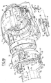
- Figur 2 ein Schnitt durch die Steckdose nach der Erfindung in montiertem Zustand ist, wobei ein Aufnahmeraum für ein Befestigungselement der Steckdose um 60° verdreht dargestellt ist.
- Figure 1A is a partially exploded perspective view with parts broken away of a contact carrier for use in a socket according to the invention;
- Figure 1B is a partially broken perspective view of a support member and housing of the socket according to the invention; and
- Figure 2 is a section through the socket according to the invention in the assembled state, wherein a receiving space for a fastening element of the socket is shown rotated by 60 °.
Eine Steckdose 1 (Figur 2) ist mit einem Gehäuse 2 versehen, das an beiden Seiten offen ist und das mit einer einzigen der offenen Seiten 8 auf einem Untergrund 4 montiert werden kann. In dem Gehäuse 2 ist ein lösbarer Kontakteinsatz 2 angebracht, der aus einem mit dem Gehäuse 2 verbundenen Stützteil 6 und einem lösbar in dem Stützteil 6 angebrachten Kontaktträger 5 besteht. Das Gehäuse 2 ist mit Schrauben 7 am Untergrund 4, der beispielsweise das Heck oder die Heckstoßstange eines Fahrzeugs sein kann, befestigt. Die dem Untergrund 4 abgewandte offene Seite 9 des Gehäuses 2 wird, wenn die Steckdose 1 nicht benutzt wird, mit einem Deckel 10 verschlossen der schwenkbar um eine mit dem Gehäuse 2 verbundenen Gelenkachse 11 drehbar ist, und mittels einer Feder 12 vorgespannt wird in seinem geschlossenen Stand.A socket 1 (Figure 2) is provided with a housing 2 which is open on both sides and which can be mounted on a base 4 with a single one of the
Der Kontaktträger 5 wird von einem Klemmdeckel 13 und einem Aufnahmeteil 21 (Figur 1A) gebildet. Der Klemmdeckel 13 ist dabei mit einer Reihe von Öffnungen 14 versehen, wodurch die einzelnen Kontakte 17 hindurchgesteckt werden können. Jede Öffnung 14 wird an seinem zum Aufnahmeteil 21 gerichteten Ende von einer Anzahl kreissegmentförmiger federnder biegsamer Nocken 15 abgeschlossen, die um einen verjüngten Teil 16 jedes Kontakts 17 greifen. Die Nocken 15 sind zu ihren freien Enden hin einigermaßen abgeschrägt (Figur 2), wodurch eine zentrierende Selbstwirkung erreicht wird. Mit jedem Kontakt 17 ist ein Draht 19 verbunden, dessen eines Ende 18 in einen Aufnahmeraum 64 des Kontakts 17 gesteckt ist und darin festgeklemmt ist durch Zusammendrücken des verjüngten Teils 16. Jeder Kontakt 17 umfaßt weiter einen an seinem dem Draht 19 abgewandten mündenden Aufnahmeraum 20, in dem ein (hier nicht gezeigtes) Bein eines Kontaktsteckers aufgenommen wird.The
Das Aufnahmeteil 21 des Kontaktträgers 5 ist mit einer Anzahl von durchgehenden Öffnungen 22 zur Aufnahme der Kontakte 17 versehen. Diese Öffnungen münden in der Endfläche 24 des Aufnahmeteils 21. In seiner Frontfläche ist das Aufnahmeteil 21 mit zwei Richtstiften 23 versehen, die mit (hier nicht dargestellten) Richtöffnungen in dem Klemmdeckel 13 zusammenwirken, wodurch dieser Deckel 13 nur in einer Weise auf das Aufnahmeteil 21 aufgeschoben werden kann. Dadurch wir deine richtige Positionierung der Kontakte 17 in dem Kontaktträger 5 gewährleistet. Die Öffnungen 22 weisen einen einigermaßen erweiterten Hals auf, in den die Federnocken 15 des Klemmdeckels 13 passen (Figur 2). Dabei werden die Federnocken 15 von den Öffnungen in der Weise umschlossen, daß sie nicht auseinandergedrückt werden können und somit die Kontakte 17 in dem Deckel 13 eingeschlossen werden, sobald der Deckel 13 und das Aufnahmeteil 21 miteinander verbunden sind. Das Aufnahmeteil 21 weist eine Schulter 25 auf, dessen Funktion nachstehend klar wird. Aus der Schulter 25 ragt eine Reihe von Klemmarmen 26 heraus, die jeweils mit einem Rippensegment 27 versehen sind, welche Rippensegmente 27 mit einer umgehenden Rippe 28 auf einem Einsteckteil 29 des Klemmdeckels 13 eine Schnappverbindung bilden, wenn der Klemmdeckel 13 und das Aufnahmeteil 21 ineinander geschoben werden. Dieses Ineinanderschieben dieser beiden Teile kann erst erfolgen, nachdem Kontaktstifte 17 alle in den Öffnungen 14 des Deckels 13 angebracht sind. Zum Dichten der Verbindung zwischen dem Deckel 13 und dem Aufnahmeteil 21 ist Letzterer noch mit einem O-Ring 62 versehen. Das Aufnahmeteil 21 ist weiter noch mit einer Zentriernut 30 versehen, die zusammenwirkt mit einem Zentriernocken 31 (Figur 1B) des Stützteils 6.The receiving
Das Stützteil 6 hat dabei die Gestalt eines formfesten Rings 32 mit einer Anzahl, in dem gezeigten Beispiel zwei konzentrisch gegenüber einer Längsachse des Rings 32 angebrachten Beinen 35. Jedes Bein 35 bestimmt dabei eine Stützfläche 36, die in dem montierten Zustand der Steckdose 1 auf dem Untergrund 4 stützt (Figur 2). Das Stützteil 6 weist weiter eine Anzahl, in dem gezeigten Beispiel drei, verteilt auf seinen Umfang angebrachte Klemmorgane 38, die mit dem Kontaktträger 5 zusammenwirken. In dem gezeigten Beispiel haben die Klemmorgane 38 die Gestalt von Hakenarmen, deren Hakennasen 39 zur Längsachse des Rings 32 gerichtet sind und den Klemmdeckel 13 des Kontaktträgers 5 hintergreifen, wenn dieser in dem Stützteil 6 angebracht ist. Zwischen den Beinen 35 sind Aussparungen 37 angebracht, die als Kabeldurchführung dienen können in dem Falle, in dem die Verdrahtung nicht durch den Untergrund, sondern zu einer Seite des Gehäuses 2 geführt werden muß. Die Hakenarme 38, die federnd biegsam sind, weisen jeweils eine Andruckfläche 40 auf, die der Hakennase 39 entgegengesetzt ist, und über den Umfang des Stützrings 32 hinausragt. Diese Andruckflächen 40 sind dazu vorgesehen, mit nachstehend zu besprechenden Teilen des Gehäuses 2 zusammenzuwirken, um die Hakenarmen 38 gegen Ausbeugen zu sichern, wenn der Kontaktträger 5 in das Stützteil 6 eingerastet ist. Im Bereich der Hakenarme 38 ist das Stützteil 6 weiter mit Klemmnocken 41 versehen, mit denen das Stützteil 6 in dem Gehäuse 2 festgeklemmt werden kann. Darüber hinaus weist das Stützteil 6 einen herausragenden Zentriernocken 42 zur Zusammenwirkung mit einer in dem Gehäuse angebrachten Zentriernut auf, wodurch das Stützteil nur in einer Weise in dem Gehäuse 2 aufgenommen werden kann. Zur Dichtung ist das Stützteil 6 noch mit einem Gummiabdeckring 43 versehen, der eine Öffnung 63 aufweist, die mit der Öffnung 33 des Stützteils 6 fluchtet. Der Kontaktträger 5 kann also durch das Stützteil 6 und den Dichtungsring 43 hindurchgesteckt werden, bis seine Schulter 25 mit dem Rand der Öffnung 33 des Stützteils 6 in Angriff kommt, wobei dann die Hakenarme 38, die durch den Kontakt mit der Schulter 25 ausgebeugt sind, gerade mit ihren Hakennasen 39 gerade an der Endfläche des Klemmdeckels 13 vorbei liegen, und somit zurückfedern, wodurch der Kontaktträger 5 in dem Stützteil 6 festgeklemmt wird.The
Das Gehäuse 2 ist mit drei zylindrischen Wänden 46 versehen, die Aufnahmeräume 45 für die Befestigungselemente oder Schrauben 7 bestimmen. Die Position dieser Aufnahmeräume ist normiert. Die Position der Hakenarme 38 im Stützteil 6 ist dabei so gewählt, daß diese gerade mit den Zylinderwänden 46 fluchten. Dabei befinden sich die Andruckflächen 40 mit den Wänden 46 im Angriff, wodurch die Hakenarme 38 vor Ausbeugen gesichert sind. Um eine der Zylinderwände 46 sind zwei Zentrierrippen 47 angebracht, die zusammen eine Zentriernut 48 bestimmen. In dieser Zentriernut 48 wird der hervorrragende Zentriernocken 42 des Stützteils 6 aufgenommen, wodurch der Kontakteinsatz 3, der von dem Kontaktträger 5 und dem Stützteil 6 gebildet wird nur in einer einzigen Weise in dem Gehäuse 2 aufgenommen werden kann, und darin darüber hinaus verdrehungssicher gehalten wird. Das Gehäuse 2 umfaßt weiter eine seine Öffnung 9 umgebende Manschette 44, die mit einem nach innen ragenden Anschlagsrand 49 versehen ist, an den das Stützteil 6 in montiertem Zustand zu ruhen kommt. Zwischen der Manschette 44 und der Außenseite des Gehäuses 2 gibt es einen freien Raum 50, in dem eine elektrische Schalteinheit 57 aufgenommen werden kann, wodurch beispielsweise die Nebelschlußleuchten des Fahrzeugs, an dem die Steckdose 1 angebracht ist, automatisch abgeschaltet werden können, wenn daran ein Anhänger angekoppelt wird. Dazu sind in dem Raum 50 zwei niedrigere Böcke 51 angebracht, in denen ein Kipphebel schwenkbar gelagert werden kann. Der Kipphebel 52 weist eine Lasche 53 auf, die durch eine Öffnung 54 in der Manschette 44 bis in die Öffnung 9 des Gehäuses 2 ragt. Der Kipphebel 52 weist weiter ein Bedienungsteil 55 auf, das mit einem Mikroschalter 56 zusammenwirkt, der in einem Gehäuse 57 der Schalteinheit aufgenommen ist. Das Gehäuse 57 mit dem Mikroschalter 56 wird dabei in dem freien Raum 50 in nahe dem Kipphebel 52 geklemmt. Dazu ist das Schaltgehäuse 57 mit einem Nocken 58 versehen, der in eine Aussparung 59 in der Manschette 44 fällt. Wenn nun ein Stecker in die Öffnung 9 gesteckt wird, wird die in die Öffnung 9 steckende Lasche 53 des Kipphebels 52 nach außen gedrückt, wodurch der Kipphebel 52 um seine Achse 60 schwenkt und das Bedienungsteil 55 zum Mikroschalter 56 bewogen wird und diesen bedient. Dadurch kann dann die Stromzufuhr zu beispielsweise den Nebelschlußleuchten des Fahrzeugs unterbrochen werden. Indem die Schalteinheit 57 geteilt ausgeführt wird, kann der Mikroschalter erforderlichenfalls leicht ausgewechselt werden.The housing 2 is provided with three
Die Montage der Steckdose 1 nach der Erfindung verläuft somit durch deren spezifische Konstruktion äußerst schnell. Davon ausgehend, daß der Kontaktträger 5 in vollständig montiertem und mit Verdrahtung verbundener Form von einem Zulieferer geliefert wird, reicht es aus, im Untergrund 4 eine Öffnung anzubringen, durch die der Kontaktträger 5 gesteckt werden kann, woraufhin dieser Kontaktträger in den Stützring 6 eingerastet werden kann und der Stützring 6 seinerseits wiederum in dem Gehäuse 2 geklemmt werden kann. Danach wird das Gehäuse 2 mit Schrauben 7 am Untergrund 4 befestigt, wobei die Stützflächen 36 des Stützteils 6 mit der Unterseite des Gehäuses 2 bündig auf den Untergrund zu ruhen kommt. Die Kraft, die ausgeübt wird beim Einstecken eines Steckers in die Steckdose wird so über das Stützteil 6 unmittelbar in den Untergrund 4 geführt.The assembly of the socket 1 according to the invention thus runs extremely quickly due to its specific construction. Assuming that the
Claims (9)
Applications Claiming Priority (2)
| Application Number | Priority Date | Filing Date | Title |
|---|---|---|---|
| NL1002340A NL1002340C2 (en) | 1996-02-14 | 1996-02-14 | Socket. |
| NL1002340 | 1996-02-14 |
Publications (1)
| Publication Number | Publication Date |
|---|---|
| EP0795439A1 true EP0795439A1 (en) | 1997-09-17 |
Family
ID=19762311
Family Applications (1)
| Application Number | Title | Priority Date | Filing Date |
|---|---|---|---|
| EP97200437A Withdrawn EP0795439A1 (en) | 1996-02-14 | 1997-02-14 | Connector |
Country Status (2)
| Country | Link |
|---|---|
| EP (1) | EP0795439A1 (en) |
| NL (1) | NL1002340C2 (en) |
Cited By (6)
| Publication number | Priority date | Publication date | Assignee | Title |
|---|---|---|---|---|
| EP1006624A2 (en) * | 1998-12-01 | 2000-06-07 | ERICH JAEGER GmbH & Co. KG | Socket for electrical connections |
| EP1267453A1 (en) * | 2001-06-13 | 2002-12-18 | MENBER'S S.p.A. | Socket for electrical connection between a vehicle and a trailer |
| EP1587175A1 (en) * | 2004-04-14 | 2005-10-19 | U.I. Lapp Gmbh | Connector for signaltransmitting cable |
| WO2006005485A1 (en) * | 2004-07-10 | 2006-01-19 | Wiska Hoppmann & Mulsow Gmbh | Device for actuating a power circuit breaker arranged in a housing |
| EP1686659A1 (en) | 2005-01-31 | 2006-08-02 | ERICH JAEGER GmbH & Co. KG | Socket |
| EP2456015A3 (en) * | 2010-11-23 | 2012-07-18 | ERICH JAEGER GmbH + Co. KG | Motor vehicle coupling socket |
Citations (4)
| Publication number | Priority date | Publication date | Assignee | Title |
|---|---|---|---|---|
| DE3700511A1 (en) * | 1987-01-09 | 1988-07-21 | Schaltbau Gmbh | CONNECTOR WITH A HOUSING AND A CONTACT INSERT |
| US5011426A (en) * | 1990-02-02 | 1991-04-30 | Molex Incorporated | Electrical connector assembly for vehicular suspension system component |
| DE9201841U1 (en) * | 1991-11-28 | 1992-04-23 | Menber's Spa Construzioni Elettromeccaniche, Legnago, Verona, It | |
| EP0630078A2 (en) * | 1993-06-14 | 1994-12-21 | Sumitomo Wiring Systems, Ltd. | Charging apparatus for electric vehicle |
-
1996
- 1996-02-14 NL NL1002340A patent/NL1002340C2/en not_active IP Right Cessation
-
1997
- 1997-02-14 EP EP97200437A patent/EP0795439A1/en not_active Withdrawn
Patent Citations (4)
| Publication number | Priority date | Publication date | Assignee | Title |
|---|---|---|---|---|
| DE3700511A1 (en) * | 1987-01-09 | 1988-07-21 | Schaltbau Gmbh | CONNECTOR WITH A HOUSING AND A CONTACT INSERT |
| US5011426A (en) * | 1990-02-02 | 1991-04-30 | Molex Incorporated | Electrical connector assembly for vehicular suspension system component |
| DE9201841U1 (en) * | 1991-11-28 | 1992-04-23 | Menber's Spa Construzioni Elettromeccaniche, Legnago, Verona, It | |
| EP0630078A2 (en) * | 1993-06-14 | 1994-12-21 | Sumitomo Wiring Systems, Ltd. | Charging apparatus for electric vehicle |
Cited By (9)
| Publication number | Priority date | Publication date | Assignee | Title |
|---|---|---|---|---|
| EP1006624A2 (en) * | 1998-12-01 | 2000-06-07 | ERICH JAEGER GmbH & Co. KG | Socket for electrical connections |
| EP1006624A3 (en) * | 1998-12-01 | 2002-06-05 | ERICH JAEGER GmbH & Co. KG | Socket for electrical connections |
| EP1267453A1 (en) * | 2001-06-13 | 2002-12-18 | MENBER'S S.p.A. | Socket for electrical connection between a vehicle and a trailer |
| EP1587175A1 (en) * | 2004-04-14 | 2005-10-19 | U.I. Lapp Gmbh | Connector for signaltransmitting cable |
| WO2006005485A1 (en) * | 2004-07-10 | 2006-01-19 | Wiska Hoppmann & Mulsow Gmbh | Device for actuating a power circuit breaker arranged in a housing |
| CN100508303C (en) * | 2004-07-10 | 2009-07-01 | 维斯卡霍普曼&穆尔索有限公司 | Device for operating circuit breaker mounted in a casing |
| EP1686659A1 (en) | 2005-01-31 | 2006-08-02 | ERICH JAEGER GmbH & Co. KG | Socket |
| EP1686659B2 (en) † | 2005-01-31 | 2012-05-09 | ERICH JAEGER GmbH + Co. KG | Socket |
| EP2456015A3 (en) * | 2010-11-23 | 2012-07-18 | ERICH JAEGER GmbH + Co. KG | Motor vehicle coupling socket |
Also Published As
| Publication number | Publication date |
|---|---|
| NL1002340C2 (en) | 1997-08-15 |
Similar Documents
| Publication | Publication Date | Title |
|---|---|---|
| DE19500959C2 (en) | Electrical connector | |
| DE4433704C2 (en) | Socket | |
| DE10224757B3 (en) | Plug connector with secondary locking that locks during the plugging process | |
| EP2037545B1 (en) | Connector for a multi-terminal connector device | |
| EP0187296B1 (en) | Housing with a tiltable lamp holder for unilaterally socketed flourescent lamps | |
| DE10334655A1 (en) | Connector device for small servo motors | |
| DE19625879A1 (en) | Electrical connection structure for automobile headlamp unit | |
| DE19916075C1 (en) | Electrical plug connection, in particular for motor vehicle applications | |
| DE3532532A1 (en) | Steering-column switch for motor vehicles | |
| EP0795439A1 (en) | Connector | |
| EP1095431B1 (en) | Electrical plug-in connector | |
| DE19927198A1 (en) | Insulating lamp holder for H7 lamps for vehicle headlamps | |
| DE3720751C2 (en) | Electrical connector assembly | |
| DE202005017981U1 (en) | Contact holder for electrical plug-in connections has insulating body to accommodate contact carrier, with apertures to accommodate contact pins | |
| DE4113380A1 (en) | Cable connection socket and plug - has security ring that holds plug in latched position | |
| DE4445223A1 (en) | Head-lamp design for motor vehicle | |
| DE19736629C1 (en) | Plug socket with microswitch | |
| DE102021129406A1 (en) | Seals for a flat flexible conductor in an electrical connector assembly | |
| EP3522303B1 (en) | Terminal block | |
| DE2840781A1 (en) | PLUG-IN COUPLING FOR ELECTRIC CIRCUITS | |
| DE2046922A1 (en) | Lamp base | |
| EP0374592A2 (en) | Plug socket for a multipole plug connection for the electrical link-up of a motor vehicle trailer, and multicore conductive strand to be fitted in such a plug socket | |
| DE2109773A1 (en) | Adapter for power distribution bars | |
| DE19749852A1 (en) | Plug-connector arrangement for vehicle electrical connection | |
| EP1381118B1 (en) | Symmetrical connector |
Legal Events
| Date | Code | Title | Description |
|---|---|---|---|
| PUAI | Public reference made under article 153(3) epc to a published international application that has entered the european phase |
Free format text: ORIGINAL CODE: 0009012 |
|
| AK | Designated contracting states |
Kind code of ref document: A1 Designated state(s): AT BE DE FR IT NL SE |
|
| 17P | Request for examination filed |
Effective date: 19980317 |
|
| 17Q | First examination report despatched |
Effective date: 20030617 |
|
| GRAP | Despatch of communication of intention to grant a patent |
Free format text: ORIGINAL CODE: EPIDOSNIGR1 |
|
| STAA | Information on the status of an ep patent application or granted ep patent |
Free format text: STATUS: THE APPLICATION IS DEEMED TO BE WITHDRAWN |
|
| 18D | Application deemed to be withdrawn |
Effective date: 20060322 |