EP0795203B1 - Method of forming button-type batteries and a button-type battery insulating and sealing gasket - Google Patents
Method of forming button-type batteries and a button-type battery insulating and sealing gasket Download PDFInfo
- Publication number
- EP0795203B1 EP0795203B1 EP95940793A EP95940793A EP0795203B1 EP 0795203 B1 EP0795203 B1 EP 0795203B1 EP 95940793 A EP95940793 A EP 95940793A EP 95940793 A EP95940793 A EP 95940793A EP 0795203 B1 EP0795203 B1 EP 0795203B1
- Authority
- EP
- European Patent Office
- Prior art keywords
- terminal housing
- housing member
- stem
- gasket
- peripheral
- Prior art date
- Legal status (The legal status is an assumption and is not a legal conclusion. Google has not performed a legal analysis and makes no representation as to the accuracy of the status listed.)
- Expired - Lifetime
Links
- 238000007789 sealing Methods 0.000 title claims abstract description 29
- 238000000034 method Methods 0.000 title claims abstract description 19
- 230000002093 peripheral effect Effects 0.000 claims abstract description 49
- 238000002788 crimping Methods 0.000 claims abstract description 7
- 230000008859 change Effects 0.000 claims description 6
- 239000003792 electrolyte Substances 0.000 abstract description 7
- 238000010276 construction Methods 0.000 description 9
- 239000000463 material Substances 0.000 description 7
- 239000000853 adhesive Substances 0.000 description 4
- 230000001070 adhesive effect Effects 0.000 description 4
- -1 Polypropylene Polymers 0.000 description 2
- 239000004743 Polypropylene Substances 0.000 description 2
- 239000010426 asphalt Substances 0.000 description 2
- 238000005452 bending Methods 0.000 description 2
- 230000008901 benefit Effects 0.000 description 2
- 230000006870 function Effects 0.000 description 2
- 229920001155 polypropylene Polymers 0.000 description 2
- 230000008569 process Effects 0.000 description 2
- VGGSQFUCUMXWEO-UHFFFAOYSA-N Ethene Chemical compound C=C VGGSQFUCUMXWEO-UHFFFAOYSA-N 0.000 description 1
- 239000005977 Ethylene Substances 0.000 description 1
- 230000000694 effects Effects 0.000 description 1
- 238000007731 hot pressing Methods 0.000 description 1
- 238000001746 injection moulding Methods 0.000 description 1
- 238000003780 insertion Methods 0.000 description 1
- 230000037431 insertion Effects 0.000 description 1
- 230000002452 interceptive effect Effects 0.000 description 1
- 239000011244 liquid electrolyte Substances 0.000 description 1
- 239000002184 metal Substances 0.000 description 1
- 238000012986 modification Methods 0.000 description 1
- 230000004048 modification Effects 0.000 description 1
- 239000011148 porous material Substances 0.000 description 1
- 238000003825 pressing Methods 0.000 description 1
- 229910001220 stainless steel Inorganic materials 0.000 description 1
- 239000010935 stainless steel Substances 0.000 description 1
- 239000000126 substance Substances 0.000 description 1
- 239000011800 void material Substances 0.000 description 1
Images



Classifications
-
- H—ELECTRICITY
- H01—ELECTRIC ELEMENTS
- H01M—PROCESSES OR MEANS, e.g. BATTERIES, FOR THE DIRECT CONVERSION OF CHEMICAL ENERGY INTO ELECTRICAL ENERGY
- H01M50/00—Constructional details or processes of manufacture of the non-active parts of electrochemical cells other than fuel cells, e.g. hybrid cells
- H01M50/10—Primary casings; Jackets or wrappings
- H01M50/102—Primary casings; Jackets or wrappings characterised by their shape or physical structure
- H01M50/109—Primary casings; Jackets or wrappings characterised by their shape or physical structure of button or coin shape
-
- H—ELECTRICITY
- H01—ELECTRIC ELEMENTS
- H01M—PROCESSES OR MEANS, e.g. BATTERIES, FOR THE DIRECT CONVERSION OF CHEMICAL ENERGY INTO ELECTRICAL ENERGY
- H01M50/00—Constructional details or processes of manufacture of the non-active parts of electrochemical cells other than fuel cells, e.g. hybrid cells
- H01M50/10—Primary casings; Jackets or wrappings
- H01M50/147—Lids or covers
- H01M50/166—Lids or covers characterised by the methods of assembling casings with lids
- H01M50/167—Lids or covers characterised by the methods of assembling casings with lids by crimping
-
- H—ELECTRICITY
- H01—ELECTRIC ELEMENTS
- H01M—PROCESSES OR MEANS, e.g. BATTERIES, FOR THE DIRECT CONVERSION OF CHEMICAL ENERGY INTO ELECTRICAL ENERGY
- H01M50/00—Constructional details or processes of manufacture of the non-active parts of electrochemical cells other than fuel cells, e.g. hybrid cells
- H01M50/10—Primary casings; Jackets or wrappings
- H01M50/147—Lids or covers
- H01M50/166—Lids or covers characterised by the methods of assembling casings with lids
- H01M50/171—Lids or covers characterised by the methods of assembling casings with lids using adhesives or sealing agents
-
- H—ELECTRICITY
- H01—ELECTRIC ELEMENTS
- H01M—PROCESSES OR MEANS, e.g. BATTERIES, FOR THE DIRECT CONVERSION OF CHEMICAL ENERGY INTO ELECTRICAL ENERGY
- H01M50/00—Constructional details or processes of manufacture of the non-active parts of electrochemical cells other than fuel cells, e.g. hybrid cells
- H01M50/10—Primary casings; Jackets or wrappings
- H01M50/183—Sealing members
- H01M50/184—Sealing members characterised by their shape or structure
-
- H—ELECTRICITY
- H01—ELECTRIC ELEMENTS
- H01M—PROCESSES OR MEANS, e.g. BATTERIES, FOR THE DIRECT CONVERSION OF CHEMICAL ENERGY INTO ELECTRICAL ENERGY
- H01M6/00—Primary cells; Manufacture thereof
- H01M6/02—Details
-
- H—ELECTRICITY
- H01—ELECTRIC ELEMENTS
- H01M—PROCESSES OR MEANS, e.g. BATTERIES, FOR THE DIRECT CONVERSION OF CHEMICAL ENERGY INTO ELECTRICAL ENERGY
- H01M6/00—Primary cells; Manufacture thereof
- H01M6/04—Cells with aqueous electrolyte
- H01M6/06—Dry cells, i.e. cells wherein the electrolyte is rendered non-fluid
- H01M6/12—Dry cells, i.e. cells wherein the electrolyte is rendered non-fluid with flat electrodes
-
- H—ELECTRICITY
- H01—ELECTRIC ELEMENTS
- H01M—PROCESSES OR MEANS, e.g. BATTERIES, FOR THE DIRECT CONVERSION OF CHEMICAL ENERGY INTO ELECTRICAL ENERGY
- H01M6/00—Primary cells; Manufacture thereof
- H01M6/40—Printed batteries, e.g. thin film batteries
-
- Y—GENERAL TAGGING OF NEW TECHNOLOGICAL DEVELOPMENTS; GENERAL TAGGING OF CROSS-SECTIONAL TECHNOLOGIES SPANNING OVER SEVERAL SECTIONS OF THE IPC; TECHNICAL SUBJECTS COVERED BY FORMER USPC CROSS-REFERENCE ART COLLECTIONS [XRACs] AND DIGESTS
- Y02—TECHNOLOGIES OR APPLICATIONS FOR MITIGATION OR ADAPTATION AGAINST CLIMATE CHANGE
- Y02E—REDUCTION OF GREENHOUSE GAS [GHG] EMISSIONS, RELATED TO ENERGY GENERATION, TRANSMISSION OR DISTRIBUTION
- Y02E60/00—Enabling technologies; Technologies with a potential or indirect contribution to GHG emissions mitigation
- Y02E60/10—Energy storage using batteries
-
- Y—GENERAL TAGGING OF NEW TECHNOLOGICAL DEVELOPMENTS; GENERAL TAGGING OF CROSS-SECTIONAL TECHNOLOGIES SPANNING OVER SEVERAL SECTIONS OF THE IPC; TECHNICAL SUBJECTS COVERED BY FORMER USPC CROSS-REFERENCE ART COLLECTIONS [XRACs] AND DIGESTS
- Y02—TECHNOLOGIES OR APPLICATIONS FOR MITIGATION OR ADAPTATION AGAINST CLIMATE CHANGE
- Y02P—CLIMATE CHANGE MITIGATION TECHNOLOGIES IN THE PRODUCTION OR PROCESSING OF GOODS
- Y02P70/00—Climate change mitigation technologies in the production process for final industrial or consumer products
- Y02P70/50—Manufacturing or production processes characterised by the final manufactured product
-
- Y—GENERAL TAGGING OF NEW TECHNOLOGICAL DEVELOPMENTS; GENERAL TAGGING OF CROSS-SECTIONAL TECHNOLOGIES SPANNING OVER SEVERAL SECTIONS OF THE IPC; TECHNICAL SUBJECTS COVERED BY FORMER USPC CROSS-REFERENCE ART COLLECTIONS [XRACs] AND DIGESTS
- Y10—TECHNICAL SUBJECTS COVERED BY FORMER USPC
- Y10T—TECHNICAL SUBJECTS COVERED BY FORMER US CLASSIFICATION
- Y10T29/00—Metal working
- Y10T29/49—Method of mechanical manufacture
- Y10T29/49002—Electrical device making
- Y10T29/49108—Electric battery cell making
-
- Y—GENERAL TAGGING OF NEW TECHNOLOGICAL DEVELOPMENTS; GENERAL TAGGING OF CROSS-SECTIONAL TECHNOLOGIES SPANNING OVER SEVERAL SECTIONS OF THE IPC; TECHNICAL SUBJECTS COVERED BY FORMER USPC CROSS-REFERENCE ART COLLECTIONS [XRACs] AND DIGESTS
- Y10—TECHNICAL SUBJECTS COVERED BY FORMER USPC
- Y10T—TECHNICAL SUBJECTS COVERED BY FORMER US CLASSIFICATION
- Y10T29/00—Metal working
- Y10T29/49—Method of mechanical manufacture
- Y10T29/49002—Electrical device making
- Y10T29/49108—Electric battery cell making
- Y10T29/4911—Electric battery cell making including sealing
-
- Y—GENERAL TAGGING OF NEW TECHNOLOGICAL DEVELOPMENTS; GENERAL TAGGING OF CROSS-SECTIONAL TECHNOLOGIES SPANNING OVER SEVERAL SECTIONS OF THE IPC; TECHNICAL SUBJECTS COVERED BY FORMER USPC CROSS-REFERENCE ART COLLECTIONS [XRACs] AND DIGESTS
- Y10—TECHNICAL SUBJECTS COVERED BY FORMER USPC
- Y10T—TECHNICAL SUBJECTS COVERED BY FORMER US CLASSIFICATION
- Y10T29/00—Metal working
- Y10T29/49—Method of mechanical manufacture
- Y10T29/49002—Electrical device making
- Y10T29/49108—Electric battery cell making
- Y10T29/49114—Electric battery cell making including adhesively bonding
Definitions
- This invention relates to methods of forming button-type batteries and to button-type battery insulating and sealing gaskets.
- Button-type batteries are small, thin energy cells that are commonly used in watches and other electronic devices requiring a thin profile.
- a conventional button-type battery includes two electrodes in the form of an anode and a cathode. These are typically separated by a porous separator. An electrolyte is present within pores of the separator.
- the internal battery components are housed within a metal casing or housing formed by a lower conductive can and an upper conductive lid.
- a common prior art material for the can and lid is stainless steel.
- the can is typically in electrical contact with the cathode to form the positive battery terminal, and the lid is in electrical contact with the anode to form the negative battery terminal.
- the can and lid are crimped or pressed together to form a fluid-tight seal which entirely encloses the anode, cathode, separator, and electrolyte.
- An electrically insulating sealing gasket is provided within the primary seal between the lid and can to electrically isolate the two housing members.
- EP0089496 discloses a sealing gasket for an electro-chemical cell having an outer upstanding flange adapted for being compressed between the upper side wall of the container and the peripheral edge of the cover to seal the cell, and an inner upstanding flange adapted to be turned over the peripheral edge of the separator so as to effectively secure and isolate the cathode disposed under the separator under cover of the cell.
- the present invention principally concerns the provision of the sealing gasket material within the crimp.
- a button-type battery sealing gasket according to claim 1.
- a button-type battery according to claim 4.
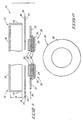
- button-type battery components for assembly are indicated generally with reference numeral 10.
- Such are comprised of a first terminal housing member 12 having a surrounding peripheral portion 14 and a central portion 10 intermediate surrounding peripheral portion 14.
- Portion 14 is in the form of a substantially normal peripheral container wall which projects transversely relative to central portion 16.
- container wall 14 projects to a first distance 18 relative to central portion 16.
- An example first distance 18 would be 0.033 inches.
- the button-type battery components also include a second terminal housing member 20 having a surrounding peripheral portion 22 and a central portion 24 intermediate peripheral portion 22.
- first terminal housing member 12 is commonly referred to as a "container” or “can”, while second terminal housing member 20 is typically referred to as a "lid”.
- Second terminal housing member 20 and first terminal housing member 12 are positioned in opposing facing juxtaposition to one another.
- An anode 26, a cathode 28 and liquid electrolyte 30 are provided intermediate first and second terminal housing member central portions 16 and 24, respectively.
- a porous separator 32 is also typically provided intermediate cathode 28 and anode 26.
- Components 26, 28, 30 and 32 could be provided either within first terminal housing member 12 or second terminal housing member 20, with positioning relative to second terminal housing member 20 being shown and preferred.
- a peripheral sealing gasket 34 is provided intermediate first terminal housing member 12 and second terminal housing member 20.
- Gasket 34 is in the shape of an annulus, and has a radial extent 36 which extends radially outward beyond surrounding peripheral portions 14 and 22, as shown. Radial extent 36 defines a second distance which is less than first distance 18.
- Gasket 34 has opposing first and second faces 38, 40, respectively, with first face 38 facing first terminal housing member 12 and second face 40 facing second terminal housing member 20.
- Gasket 34 is of constant thickness (Fig. 1) and has a constant outer radius (Fig. 2).
- gasket second face 40 is adhered against second terminal housing member peripheral portion 22 prior to the step of positioning the first and second terminal housing members in juxtaposition to one another.
- An example and preferred adhesive is a tacky asphalt, such as Pioneer 760TM made by Pioneer Asphalt Company of Lawrenceville, Illinois.
- gasket first face 38 is placed against container wall 14 prior to the step of positioning the first and second terminal members in juxtaposition to one another.
- an adhesive such as the above Pioneer 760TM is used intermediate gasket first face 38 and container wall 14 for temporarily retaining gasket 34 in the illustrated position.
- the adhesive should not, however, be so strong as to prevent subsequent breaking and sliding of gasket 34 relative to walls 14, as will be apparent from the continuing discussion.
- the anode, the cathode, the electrolyte, and the separator are positioned relative to one of the first or second housing members before the step of providing gasket 34 in its intermediate position.
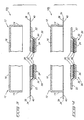
- first terminal housing member 12 or second terminal housing member 20 is moved in the direction of the other to push first terminal housing member peripheral wall 14 against first gasket face 38 and to simultaneously force second terminal housing member peripheraL portion 22 against second gasket face 40.
- This will cause sliding movement of first gasket face 38 relative to the outer edge of container wall 14, as well as bending oF gasket 34 (Fig. 5).
- Such movement is continued to bend insulative gasket 34 about container wall 14 and force gasket 34 to be received within first terminal housing member 12 (Fig. 6).
- container wall 14 and adjoining sealing gasket material 34 are crimped against peripheral portion 22 of second terminal housing member 20 (Fig.
- Fig. 7 illustrates a finished construction designated with numeral 45.
- second distance 36 is preferably gauged to be less than first distance 18 such that upon finished folding and crimping, the outer terminus of gasket 34 aligns with the outer terminus of crimped container wall 14. Due to container wall 14 being bent about an effective larger radius than gasket 34, second distance 36 will be less than first distance 18 to accomplish such objective.
- Fig. 8 illustrates an alternate embodiment 45a whereby second distance 36 is greater than or equal to first distance 18.
- gasket 34a has an outer terminus which projects outwardly beyond the terminus of container wall 14 after crimping. Such would provide an advantage of positioning insulative material between can 12 and lid 20 in this region.
- gasket 34 can be constructed to extend radially inward to contact the outer radial edge of cathode 28, thereby providing an alignment function within the housing relative for cathode 28.
- a method of forming a button-type battery as described above enables the gasket to be made from extremely thin sheet stock, and minimizes final battery thickness.
- Preferred thickness is from 2 to 4 mils.
- Polypropylene is a preferred material which can be formed by cold pressing or hot pressing.
- Current button-type battery gaskets in industry are formed by injection molding, and are difficult to produce in desired shapes at thicknesses less than 7 mils.
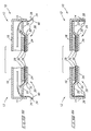
- An alternate example and method of construction are described with reference to Figs. 9-13. For simplification and ease of discussion, no anode, cathode, or electrolyte are shown with respect to the construction. Like numerals from the first-described embodiments are utilized where appropriate, with differences of construction being indicated with different numerals.
- An insulative sealing gasket 50 is provided as a discrete, pre-formed mass in the shape of an annulus. Such comprises at least in part a substantially annular "L" cross-sectional shape, defining an annular "L" base portion 52 and an annular "L" stem portion 54.
- discrete pre-formed sealing gasket 50 is positioned within first terminal housing - member 12 with "L" stem portion 54 extending internally along container peripheral wall 14.
- gasket base 52 is adhered by a tacky adhesive to first terminal housing member 12, with the Pioneer 760TM being an example.
- Second terminal housing member 20 is moved into facing juxtaposition against "L" base portion 52 of sealing gasket 50.
- container wall 14 and gasket stem 54 are crimped against peripheral portion 22 of second terminal housing member 20 to form an enclosing housing which retains and protects the anode, cathode and the electrolyte (not shown).
- the finished construction is indicated with numeral 51.
- a preferred material of construction is polypropylene having from 1% to 3% ethylene.
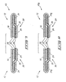
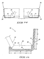
- a preferred embodiment button-type battery insulative sealing gasket is indicated generally with reference numeral 56 in Figs. 14-16.
- Such is comprised of an annular body 58 having a substantially "L" cross-sectional shape.
- the "L" cross-sectional shape defines an annular "L” base portion 60 and an annular “L” stem portion 70.
- Base portion 60 is configured to receive an inner sealing portion of a peripheral portion 22 of a button-type battery terminal lid 20 for which the gasket is principally adapted.
- "L" base portion 60 has a radial length 62 (Fig. 15) and, for purposes of discussion, has an inner radial portion 64 and an outer radial portion 66.
- Base portion 60 has a thickness which varies along its radial length 62, being greater at inner radial portion 64 than at outer radial portion 66.
- the illustrated change in the base portion thickness preferably occurs along a base arc 68 which is sized and shaped to mate with a correspondingly shaped arc of peripheral portion 22 of button-type a battery terminal lid 20 for which gasket 56 is adapted.
- Stem portion 70 is configured to receive an outer sealing portion or surface 99 (Fig. 15) of peripheral portion 22 of button-type battery terminal lid 20.
- Stem portion 70 has a transverse length 72 which, for purposes of the continuing discussion, defines an inner transverse portion 76 and an outer transverse portion 78.
- "L" stem portion 70 also has a thickness which varies along its transverse length 72, with the stem thickness being greater at inner transverse portion 76 than at outer transverse portion 78.
- the thickness change for stem portion 70 occurs at a substantially perpendicular step 80, as opposed to along an arc as occurs in the base portion.
- Stem portion 70 angles from base portion 60 at slightly greater than 90°. This makes it easier to insert gasket 56 into the can and prevent stem portion 70 from folding inward and interfering with lid insertion.
- the components are positioned and crimped as shown to produce a peripheral seal for a button-type battery.
- a gasket construction provides two advantages. First, the greater mass of material defined at the gasket fold by step 80 substantially completely fills any outer void between lid 20 and can 12. Second, the enlarged inner radial portion of base 60 defined by arc 68 can be utilized to engage the outer radial edge of the cathode (not shown) to provide an alignment function with the battery to such cathode.
Landscapes
- Chemical & Material Sciences (AREA)
- Chemical Kinetics & Catalysis (AREA)
- Electrochemistry (AREA)
- General Chemical & Material Sciences (AREA)
- Engineering & Computer Science (AREA)
- Manufacturing & Machinery (AREA)
- Sealing Battery Cases Or Jackets (AREA)
- Primary Cells (AREA)
Abstract
Description
Claims (8)
- An button-type battery insulative sealing gasket (56) comprising:an annular body (58) at least a portion of which has a substantially "L" cross sectional shape;the "L" cross sectional shape defining an annular "L" base portion (60), the "L" base portion being configured to receive an inner sealing portion of a peripheral portion of a button-type battery terminal lid (20), the "L" base portion having a radial length and an inner radial portion (64) and an outer radial portion (66);the "L" cross sectional shape defining an annular "L" stem portion (70), the "L" stem portion being configured to receive an outer sealing portion of the peripheral portion (22) of the button-type battery terminal lid, the "L" stem portion having a transverse length and an inner transverse portion (76) and an outer transverse portion (78), the "L" stem portion having a thickness which varies along its transverse length (72), the stem thickness being greater at the inner transverse portion (76) than at the outer transverse portion (78); andthe "L" base portion (60) having a thickness which varies along its radial length (62), the base thickness being greater at the inner radial portion (64) than at the outer radial portion (66).
- The button-type battery insulative sealing gasket of claim 1 wherein the change in the stem portion thickness occurs at a substantially perpendicular step (80).
- The button-type battery insulative sealing gasket of claim 1, wherein the change in the base portion thickness occurring along a base arc (68), the base arc being sized and shaped to mate with a correspondingly shaped arc of the peripheral portion of the button-type battery terminal lid for which the gasket is adapted.
- A button type battery comprising:a conductive first terminal housing member (12) having a surrounding peripheral portion which comprises a transversely projecting peripheral container wall (16), the peripheral container wall having an inner surface and an outer surface;a conductive second terminal housing member (20) having a surrounding peripheral portion (22) which has an upper surface and a lower surface;a gasket (56) in the shape of an annulus and comprising at least in part a substantially annular "L" cross sectional shape defining an annular "L" base portion (60) and an "L" stem portion (70),
the "L" base portion (60) having a thickness which varies along its radial length (62), the base thickness being greater at the inner radial portion (64) than at the outer radial portion (66); the "L" stem portion varying in thickness along its length (72), its thickness being greater at a part of the stem (76) near the "L" base than at a part of the stem (78) remote from the "L" base;the lower surface of the second terminal housing member peripheral portion (22) being received against the "L" base portion (60) of the gasket, the "L" stem portion (70) of the gasket extending along the inner surface of the peripheral container wall (16), the "L" stem (70) and the peripheral container wall (16) being crimped against the upper surface of the peripheral portion (22) of the second terminal housing member so as to form an enclosed housing. - A button type battery according to claim 4 wherein said "L" stem portion (70) includes a step portion (80) and an above-step portion, the step portion (80) being of greater thickness than the above step portion and having an upper surface which is substantially perpendicular to a lateral surface of the stem, the above-step section of the stem portion being bent over and against the upper surface of the step and extending radially inward to cover the peripheral portion (22) of the second terminal housing member.
- A method of forming a button-type battery, comprising:providing a conductive first terminal housing member (12) having a surrounding peripheral portion which comprises a transversely projecting peripheral container wall (16);providing a conductive second terminal housing member (20) having a surrounding peripheral portion (22);providing a gasket (56), the gasket being in the shape of an annulus and comprising at least in part a substantially annular "L" cross sectional shape defining an annular "L" base portion (60) and an annular "L" stem portion (70), the "L" base portion comprising a radial length (62) and an inner radial portion (64) and an outer radial portion (66), the "L" base portion having a thickness which varies along its radial length (62), said thickness being greater at the inner radial portion (64) than at the outer radial portion (66); the "L" stem portion (70) having a transverse length (72) and an inner transverse portion (76) and an outer transverse portion (78), the "L" stem portion having a thickness which varies along its transverse length, the stem thickness being greater at the inner transverse portion (76) than at the outer transverse portion (78);positioning the gasket (56) within the first terminal housing member (12) with the "L" stem portion (70) extending internally along the peripheral container wall (16), positioning the second terminal housing member (20) and the first terminal housing member (12) in facing juxtaposition to one another with the second terminal housing member peripheral portion (22) being received against the "L" base portion (70) of the gasket; andcrimping the first terminal housing member peripheral container wall (16) and sealing gasket (56) against the peripheral portion (22) of the second terminal housing member to form an enclosed housing.
- The method of claim 6 wherein the change in the base portion thickness occurs along a base arc (68), the base arc being sized and shaped to meet with a correspondingly shaped arc of a peripheral portion of a button-type battery terminal lid.
- The method of claim 6, wherein the change in the stem portion thickness occurs at a substantially perpendicular step (80), the step comprising an upper surface which is substantially perpendicular to a lateral surface (72) of the stem portion; the stem portion comprising an above-step section elevationally above the step,
wherein the act of positioning comprises positioning the gasket (56) within the first terminal housing member (12) with the "L" stem portion (70) extending internally along the peripheral container wall (16), positioning the second terminal housing member (20) and the first terminal housing member (12) in facing juxtaposition to one another with the second terminal housing member peripheral portion (22) being received against the "L" base portion (60) of the gasket (56); and
wherein the act of crimping comprises crimping the first terminal housing member peripheral container wall (16) and sealing gasket (56) against the peripheral portion (22) of the second terminal housing member to form an enclosed housing, wherein the crimping folds the above-step section of the stem portion over and against the upper surface of the step (80).
Priority Applications (1)
| Application Number | Priority Date | Filing Date | Title |
|---|---|---|---|
| EP01122089A EP1217669B1 (en) | 1994-12-01 | 1995-11-13 | Method of formimg button-type batteries and button-type battery insulating and sealing gasket |
Applications Claiming Priority (3)
| Application Number | Priority Date | Filing Date | Title |
|---|---|---|---|
| US348543 | 1990-04-03 | ||
| US34854394A | 1994-12-01 | 1994-12-01 | |
| PCT/US1995/015192 WO1996017390A1 (en) | 1994-12-01 | 1995-11-13 | Method of forming button-type batteries and a button-type battery insulating and sealing gasket |
Related Child Applications (1)
| Application Number | Title | Priority Date | Filing Date |
|---|---|---|---|
| EP01122089A Division EP1217669B1 (en) | 1994-12-01 | 1995-11-13 | Method of formimg button-type batteries and button-type battery insulating and sealing gasket |
Publications (2)
| Publication Number | Publication Date |
|---|---|
| EP0795203A1 EP0795203A1 (en) | 1997-09-17 |
| EP0795203B1 true EP0795203B1 (en) | 2003-01-22 |
Family
ID=23368479
Family Applications (2)
| Application Number | Title | Priority Date | Filing Date |
|---|---|---|---|
| EP95940793A Expired - Lifetime EP0795203B1 (en) | 1994-12-01 | 1995-11-13 | Method of forming button-type batteries and a button-type battery insulating and sealing gasket |
| EP01122089A Expired - Lifetime EP1217669B1 (en) | 1994-12-01 | 1995-11-13 | Method of formimg button-type batteries and button-type battery insulating and sealing gasket |
Family Applications After (1)
| Application Number | Title | Priority Date | Filing Date |
|---|---|---|---|
| EP01122089A Expired - Lifetime EP1217669B1 (en) | 1994-12-01 | 1995-11-13 | Method of formimg button-type batteries and button-type battery insulating and sealing gasket |
Country Status (9)
| Country | Link |
|---|---|
| US (5) | US5662718A (en) |
| EP (2) | EP0795203B1 (en) |
| JP (1) | JP2991776B2 (en) |
| KR (1) | KR100360321B1 (en) |
| AT (1) | ATE556442T1 (en) |
| AU (1) | AU4243096A (en) |
| DE (1) | DE69529476T2 (en) |
| TW (1) | TW345757B (en) |
| WO (1) | WO1996017390A1 (en) |
Families Citing this family (25)
| Publication number | Priority date | Publication date | Assignee | Title |
|---|---|---|---|---|
| DE69529476T2 (en) * | 1994-12-01 | 2003-11-27 | Micron Technology, Inc. | METHOD FOR PRODUCING BUTTON BATTERIES, BUTTON BATTERY INSULATION AND SEALING RING |
| US5755831A (en) | 1995-02-22 | 1998-05-26 | Micron Communications, Inc. | Method of forming a button-type battery and a button-type battery with improved separator construction |
| US6130602A (en) | 1996-05-13 | 2000-10-10 | Micron Technology, Inc. | Radio frequency data communications device |
| US6289209B1 (en) | 1996-12-18 | 2001-09-11 | Micron Technology, Inc. | Wireless communication system, radio frequency communications system, wireless communications method, radio frequency communications method |
| US5842118A (en) * | 1996-12-18 | 1998-11-24 | Micron Communications, Inc. | Communication system including diversity antenna queuing |
| US6104333A (en) | 1996-12-19 | 2000-08-15 | Micron Technology, Inc. | Methods of processing wireless communication, methods of processing radio frequency communication, and related systems |
| JP3199000B2 (en) | 1997-10-24 | 2001-08-13 | 松下電器産業株式会社 | Flat battery and its manufacturing method |
| US6001504A (en) * | 1998-03-11 | 1999-12-14 | Duracell Inc. | Prismatic battery housing |
| EP1035598A4 (en) * | 1998-09-01 | 2007-07-11 | Matsushita Electric Industrial Co Ltd | CELL-SHAPED CELL AND METHOD OF MANUFACTURING THE SAME |
| WO2000035033A1 (en) * | 1998-12-10 | 2000-06-15 | Matsushita Electric Industrial Co., Ltd. | Flat battery and production method thereof |
| KR100404689B1 (en) * | 2000-10-24 | 2003-11-07 | 한국 파워셀 주식회사 | Lithium ion secondary battery |
| US6673489B2 (en) * | 2001-12-28 | 2004-01-06 | Quallion Llc | Electric battery assembly and method of manufacture |
| US7118828B2 (en) * | 2002-03-11 | 2006-10-10 | Quallion Llc | Implantable battery |
| JP4786159B2 (en) * | 2004-09-22 | 2011-10-05 | 日産自動車株式会社 | Battery storage container and assembly method thereof |
| KR100760757B1 (en) * | 2005-12-29 | 2007-09-21 | 삼성에스디아이 주식회사 | Lithium secondary battery |
| EP2211398B1 (en) * | 2009-01-19 | 2018-01-10 | Renata AG | Heavy-duty galvanic element |
| US9196920B2 (en) * | 2011-10-18 | 2015-11-24 | Johnson Controls Technology Llc | Electrochemical cell having a safety device |
| US10164306B2 (en) * | 2013-11-15 | 2018-12-25 | Energizer Brands, Llc | Battery cell having inward extending cup edge and method of manufacture |
| CA3027200A1 (en) | 2016-06-13 | 2017-12-21 | Massachusetts Institute Of Technology | Biocompatible zwitterionic polymer coatings and hydrogels for reducing foreign body response and fibrosis |
| US10170974B1 (en) | 2017-07-28 | 2019-01-01 | Apple Inc. | Variable frequency and burst mode operation of primary resonant flyback converters |
| US10707699B2 (en) | 2017-09-28 | 2020-07-07 | Apple Inc. | Interphase transformer based rectifier for wireless power transfer |
| CN109802059B (en) * | 2017-11-17 | 2022-04-08 | 宁德新能源科技有限公司 | Battery |
| EP3509123B1 (en) * | 2018-01-09 | 2020-11-18 | Renata AG | Cell and method for manufacturing such a cell |
| KR102866763B1 (en) | 2019-08-19 | 2025-09-29 | 삼성에스디아이 주식회사 | Rechargeable battery |
| US12301118B2 (en) | 2022-02-28 | 2025-05-13 | Apple Inc. | Forward mode soft switching power converter |
Family Cites Families (57)
| Publication number | Priority date | Publication date | Assignee | Title |
|---|---|---|---|---|
| BE461534A (en) * | 1945-07-10 | |||
| NL189747B (en) * | 1953-08-07 | Benzon Pharma As | DOSING UNIT FOR CONTROLLED DISPENSING OF DRUGS. | |
| US2836643A (en) * | 1954-08-30 | 1958-05-27 | Pertrix Union Gmbh | Galvanic battery |
| US2951891A (en) * | 1957-11-20 | 1960-09-06 | Hamilton Watch Co | Battery case construction |
| US3004094A (en) * | 1958-06-03 | 1961-10-10 | Union Carbide Corp | Method of making unit wafer cells |
| US3068313A (en) * | 1958-11-19 | 1962-12-11 | Union Carbide Corp | High pressure mechanical seal gasket |
| US3023259A (en) * | 1959-11-18 | 1962-02-27 | Myron A Coler | Flexible battery |
| NL269881A (en) * | 1960-10-04 | |||
| US3290763A (en) * | 1962-05-25 | 1966-12-13 | Crawford Fitting Co | Method of connecting multiple fluid lines |
| US3185595A (en) * | 1963-04-24 | 1965-05-25 | Union Carbide Corp | Reinforced cell closure |
| US3290753A (en) * | 1963-08-19 | 1966-12-13 | Bell Telephone Labor Inc | Method of making semiconductor integrated circuit elements |
| DE1270144B (en) * | 1965-05-03 | 1968-06-12 | Varta G M B H | Galvanic element with elastic seal |
| US3457117A (en) * | 1967-03-23 | 1969-07-22 | Mallory & Co Inc P R | Leakproof electrochemical cell |
| BE759896R (en) * | 1969-05-01 | 1971-05-17 | Leclanche Sa | ANTI-MAGNETIC ALKALINE ELEMENT |
| US3713896A (en) * | 1970-08-19 | 1973-01-30 | Esb Inc | Seal for electrochemical cells |
| US3708343A (en) * | 1971-01-18 | 1973-01-02 | Timex Corp | Primary cell case |
| US3799959A (en) * | 1971-10-12 | 1974-03-26 | Mallory & Co Inc P R | Alkaline dry cell and permanganate cathode therefor |
| US3741812A (en) * | 1971-11-03 | 1973-06-26 | Esb Inc | Battery having gas pervious liquid impervious member sealed over holein top |
| US3884723A (en) * | 1973-10-12 | 1975-05-20 | Du Pont | Button type galvanic cell |
| US3891462A (en) * | 1973-10-29 | 1975-06-24 | Union Carbide Corp | Galvanic cell structure |
| US4025702A (en) * | 1975-03-10 | 1977-05-24 | Citizen Watch Co., Ltd. | Battery construction |
| US3935026A (en) * | 1975-04-14 | 1976-01-27 | Timex Corporation | Energy cell for watch |
| US4048405A (en) * | 1976-03-15 | 1977-09-13 | Esb Incorporated | High drain rate, primary alkaline cell having a divalent silver oxide/monovalent silver oxide depolarizer blend coated with a layer of silver |
| JPS536835A (en) * | 1976-07-07 | 1978-01-21 | Matsushita Electric Industrial Co Ltd | Flat battery |
| US4212021A (en) * | 1976-07-21 | 1980-07-08 | Hitachi, Ltd. | Light emitting devices |
| JPS5359829A (en) * | 1976-11-10 | 1978-05-30 | Suwa Seikosha Kk | Miniature electronic device |
| US4121020A (en) * | 1977-01-21 | 1978-10-17 | Gte Laboratories Incorporated | Ultra-thin button-type primary electrochemical cell |
| US4122241A (en) * | 1977-03-11 | 1978-10-24 | P. R. Mallory & Co. Inc. | Modified grommet for long term use cells |
| JPS5481422U (en) * | 1977-11-21 | 1979-06-09 | ||
| CH639512A5 (en) * | 1978-07-06 | 1983-11-15 | Leclanche Sa | LOW-WATER ALKALINE PRIMARY CELL WITH LONG LIFE. |
| DE2842697C2 (en) * | 1978-09-30 | 1980-08-28 | Varta Batterie Ag, 3000 Hannover | Galvanic element and process for its manufacture |
| EP0022223B2 (en) * | 1979-06-28 | 1987-11-11 | Hitachi Maxell Ltd. | Leak-proof electrochemical cell |
| US4256815A (en) * | 1980-01-21 | 1981-03-17 | Union Carbide Corporation | Seals for electrochemical cells |
| JPS579056A (en) * | 1980-06-19 | 1982-01-18 | Yuasa Battery Co Ltd | Sealed alkaline battery |
| US4374186A (en) * | 1981-04-29 | 1983-02-15 | The United States Of America As Represented By The Secretary Of The Navy | Polymer packaged cell in a sack |
| US4374909A (en) * | 1981-06-26 | 1983-02-22 | Union Carbide Corporation | Seals for electrochemical cells |
| US4409730A (en) * | 1981-11-09 | 1983-10-18 | Gte Products Corporation | Method for fabricating multi-element anode structures for electrochemical cells |
| US4521500A (en) * | 1981-12-04 | 1985-06-04 | Hitachi Maxell Limited | Leak-proof alkaline cell |
| US4656104A (en) * | 1982-03-19 | 1987-04-07 | Union Carbide Corporation | Sealing gasket for electrochemical cells |
| EP0089495A1 (en) * | 1982-03-19 | 1983-09-28 | Union Carbide Corporation | Sealing gasket for electrochemical cells and electrochemical cell employing such gasket |
| US4457990A (en) | 1982-03-19 | 1984-07-03 | Union Carbide Corporation | Thin miniature cell construction with reshaped gasket |
| JPS598262A (en) * | 1982-07-06 | 1984-01-17 | Matsushita Electric Ind Co Ltd | Sealed battery |
| US4537647A (en) * | 1982-10-06 | 1985-08-27 | The Boeing Company | Method for applying turbulators to wind tunnel models |
| US4501805A (en) * | 1983-12-22 | 1985-02-26 | Union Carbide Corporation | Galvanic cell having a saturated fluorocarbon plasma-treated sealing gasket |
| DE3425170A1 (en) * | 1984-07-09 | 1986-01-16 | Varta Batterie Ag, 3000 Hannover | GALVANIC PRIME ELEMENT |
| JPS61163559A (en) * | 1985-01-16 | 1986-07-24 | Matsushita Electric Ind Co Ltd | flat battery |
| JP3019326B2 (en) * | 1989-06-30 | 2000-03-13 | 松下電器産業株式会社 | Lithium secondary battery |
| US5180645A (en) * | 1991-03-01 | 1993-01-19 | Motorola, Inc. | Integral solid state embedded power supply |
| EP0573040B1 (en) * | 1992-06-04 | 1997-09-24 | Matsushita Electric Industrial Co., Ltd. | A positive electrode for lithium secondary battery and its method of manufacture, and a nonaqueous electrolyte lithium secondary battery employing the positive electrode |
| US5338625A (en) * | 1992-07-29 | 1994-08-16 | Martin Marietta Energy Systems, Inc. | Thin film battery and method for making same |
| US5288565A (en) * | 1993-02-08 | 1994-02-22 | Globe-Union Inc. | Support extension for flat pack rechargeable batteries |
| US5512387A (en) * | 1993-11-19 | 1996-04-30 | Ovonic Battery Company, Inc. | Thin-film, solid state battery employing an electrically insulating, ion conducting electrolyte material |
| US5547781A (en) * | 1994-03-02 | 1996-08-20 | Micron Communications, Inc. | Button-type battery with improved separator and gasket construction |
| US5486431A (en) * | 1994-03-02 | 1996-01-23 | Micron Communications, Inc. | Method of producing button-type batteries and spring-biased concave button-type battery |
| US5432027A (en) * | 1994-03-02 | 1995-07-11 | Micron Communications, Inc. | Button-type battery having bendable construction, and angled button-type battery |
| US5494495A (en) * | 1994-10-11 | 1996-02-27 | Micron Communications, Inc. | Method of forming button-type batteries |
| DE69529476T2 (en) * | 1994-12-01 | 2003-11-27 | Micron Technology, Inc. | METHOD FOR PRODUCING BUTTON BATTERIES, BUTTON BATTERY INSULATION AND SEALING RING |
-
1995
- 1995-11-13 DE DE69529476T patent/DE69529476T2/en not_active Expired - Lifetime
- 1995-11-13 EP EP95940793A patent/EP0795203B1/en not_active Expired - Lifetime
- 1995-11-13 AU AU42430/96A patent/AU4243096A/en not_active Abandoned
- 1995-11-13 JP JP8518910A patent/JP2991776B2/en not_active Expired - Fee Related
- 1995-11-13 AT AT01122089T patent/ATE556442T1/en active
- 1995-11-13 EP EP01122089A patent/EP1217669B1/en not_active Expired - Lifetime
- 1995-11-13 WO PCT/US1995/015192 patent/WO1996017390A1/en not_active Ceased
- 1995-11-13 KR KR1019970703585A patent/KR100360321B1/en not_active Expired - Fee Related
- 1995-11-21 TW TW084112357A patent/TW345757B/en active
-
1996
- 1996-05-16 US US08/649,925 patent/US5662718A/en not_active Expired - Lifetime
- 1996-10-11 US US08/728,778 patent/US5843596A/en not_active Expired - Lifetime
-
1997
- 1997-07-03 US US08/888,353 patent/US5851244A/en not_active Expired - Lifetime
-
1998
- 1998-03-04 US US09/034,889 patent/US6027829A/en not_active Expired - Lifetime
- 1998-06-15 US US09/097,613 patent/US5919274A/en not_active Expired - Lifetime
Also Published As
| Publication number | Publication date |
|---|---|
| US5662718A (en) | 1997-09-02 |
| WO1996017390A1 (en) | 1996-06-06 |
| KR100360321B1 (en) | 2003-01-24 |
| AU4243096A (en) | 1996-06-19 |
| KR987000695A (en) | 1998-03-30 |
| JPH10507035A (en) | 1998-07-07 |
| US5843596A (en) | 1998-12-01 |
| EP0795203A1 (en) | 1997-09-17 |
| TW345757B (en) | 1998-11-21 |
| EP1217669A1 (en) | 2002-06-26 |
| EP1217669B1 (en) | 2012-05-02 |
| DE69529476D1 (en) | 2003-02-27 |
| US5919274A (en) | 1999-07-06 |
| US5851244A (en) | 1998-12-22 |
| JP2991776B2 (en) | 1999-12-20 |
| DE69529476T2 (en) | 2003-11-27 |
| US6027829A (en) | 2000-02-22 |
| ATE556442T1 (en) | 2012-05-15 |
Similar Documents
| Publication | Publication Date | Title |
|---|---|---|
| EP0795203B1 (en) | Method of forming button-type batteries and a button-type battery insulating and sealing gasket | |
| US6569564B1 (en) | Button cell constructions and thin profile battery constructions | |
| US5494495A (en) | Method of forming button-type batteries | |
| US5486431A (en) | Method of producing button-type batteries and spring-biased concave button-type battery | |
| US5725967A (en) | Battery container and method of manufacture | |
| US4725515A (en) | Button cell construction with internally compressed gasket | |
| KR100300405B1 (en) | A cap assy of second battery | |
| KR19990071646A (en) | Galvanic cells with optimal internal space for active parts | |
| JP2000067839A (en) | Rechargeable battery | |
| US5654110A (en) | Thin profile batteries and methods of forming the same | |
| US6235424B1 (en) | Cap assembly for secondary battery and method for assembling the same | |
| EP0134982B1 (en) | Sealed galvanic cell and method of producing it | |
| KR100544106B1 (en) | Can used in secondary battery | |
| CA2100391A1 (en) | Method for crimp closure of coin cell batteries | |
| US5998059A (en) | Cylindrical battery employing a separator having a protruding part | |
| RU2073286C1 (en) | Method of assembly of sealed chemical source of electric energy | |
| GB2101393A (en) | Electrical cell | |
| KR200154311Y1 (en) | Explosion Proof of Lithium Battery | |
| JPH09129201A (en) | Sealed battery | |
| EP0017436A1 (en) | Hermetically sealed electrochemical cell and method of making same | |
| JPS63264860A (en) | battery container lid | |
| MXPA98000150A (en) | A separator that has a projector and cylindrical battery that uses the mi |
Legal Events
| Date | Code | Title | Description |
|---|---|---|---|
| PUAI | Public reference made under article 153(3) epc to a published international application that has entered the european phase |
Free format text: ORIGINAL CODE: 0009012 |
|
| 17P | Request for examination filed |
Effective date: 19970624 |
|
| AK | Designated contracting states |
Kind code of ref document: A1 Designated state(s): AT BE CH DE DK ES FR GB GR IE IT LI LU MC NL PT SE Kind code of ref document: A1 Designated state(s): DE GB |
|
| 17Q | First examination report despatched |
Effective date: 19990419 |
|
| RAP1 | Party data changed (applicant data changed or rights of an application transferred) |
Owner name: MICRON TECHNOLOGY, INC. |
|
| GRAG | Despatch of communication of intention to grant |
Free format text: ORIGINAL CODE: EPIDOS AGRA |
|
| GRAG | Despatch of communication of intention to grant |
Free format text: ORIGINAL CODE: EPIDOS AGRA |
|
| GRAH | Despatch of communication of intention to grant a patent |
Free format text: ORIGINAL CODE: EPIDOS IGRA |
|
| GRAH | Despatch of communication of intention to grant a patent |
Free format text: ORIGINAL CODE: EPIDOS IGRA |
|
| GRAA | (expected) grant |
Free format text: ORIGINAL CODE: 0009210 |
|
| RBV | Designated contracting states (corrected) |
Designated state(s): DE GB |
|
| AK | Designated contracting states |
Kind code of ref document: B1 Designated state(s): DE GB |
|
| REG | Reference to a national code |
Ref country code: GB Ref legal event code: FG4D |
|
| REG | Reference to a national code |
Ref country code: IE Ref legal event code: FG4D |
|
| REF | Corresponds to: |
Ref document number: 69529476 Country of ref document: DE Date of ref document: 20030227 Kind code of ref document: P |
|
| PLBE | No opposition filed within time limit |
Free format text: ORIGINAL CODE: 0009261 |
|
| STAA | Information on the status of an ep patent application or granted ep patent |
Free format text: STATUS: NO OPPOSITION FILED WITHIN TIME LIMIT |
|
| 26N | No opposition filed |
Effective date: 20031023 |
|
| REG | Reference to a national code |
Ref country code: IE Ref legal event code: MM4A |
|
| PGFP | Annual fee paid to national office [announced via postgrant information from national office to epo] |
Ref country code: GB Payment date: 20131113 Year of fee payment: 19 Ref country code: DE Payment date: 20131106 Year of fee payment: 19 |
|
| REG | Reference to a national code |
Ref country code: DE Ref legal event code: R119 Ref document number: 69529476 Country of ref document: DE |
|
| GBPC | Gb: european patent ceased through non-payment of renewal fee |
Effective date: 20141113 |
|
| PG25 | Lapsed in a contracting state [announced via postgrant information from national office to epo] |
Ref country code: DE Free format text: LAPSE BECAUSE OF NON-PAYMENT OF DUE FEES Effective date: 20150602 Ref country code: GB Free format text: LAPSE BECAUSE OF NON-PAYMENT OF DUE FEES Effective date: 20141113 |