EP0795108B1 - Method and device for readjusting the heat transfer surface of a fluidized bed - Google Patents
Method and device for readjusting the heat transfer surface of a fluidized bed Download PDFInfo
- Publication number
- EP0795108B1 EP0795108B1 EP95914650A EP95914650A EP0795108B1 EP 0795108 B1 EP0795108 B1 EP 0795108B1 EP 95914650 A EP95914650 A EP 95914650A EP 95914650 A EP95914650 A EP 95914650A EP 0795108 B1 EP0795108 B1 EP 0795108B1
- Authority
- EP
- European Patent Office
- Prior art keywords
- bed
- fluidized
- heat
- tube
- area
- Prior art date
- Legal status (The legal status is an assumption and is not a legal conclusion. Google has not performed a legal analysis and makes no representation as to the accuracy of the status listed.)
- Expired - Lifetime
Links
- 238000000034 method Methods 0.000 title claims description 7
- 230000004888 barrier function Effects 0.000 claims description 20
- 239000000446 fuel Substances 0.000 claims description 13
- 238000005243 fluidization Methods 0.000 claims description 9
- 238000005192 partition Methods 0.000 claims description 8
- 230000009467 reduction Effects 0.000 claims description 4
- 238000011144 upstream manufacturing Methods 0.000 claims description 2
- 239000002826 coolant Substances 0.000 claims 4
- 230000000903 blocking effect Effects 0.000 claims 1
- 239000007789 gas Substances 0.000 description 12
- 238000002485 combustion reaction Methods 0.000 description 11
- 208000016791 bilateral striopallidodentate calcinosis Diseases 0.000 description 9
- 239000000463 material Substances 0.000 description 9
- XLYOFNOQVPJJNP-UHFFFAOYSA-N water Substances O XLYOFNOQVPJJNP-UHFFFAOYSA-N 0.000 description 7
- 239000000567 combustion gas Substances 0.000 description 5
- 238000001816 cooling Methods 0.000 description 5
- 238000004519 manufacturing process Methods 0.000 description 5
- 230000008901 benefit Effects 0.000 description 4
- 239000003245 coal Substances 0.000 description 3
- 230000003628 erosive effect Effects 0.000 description 3
- 239000002245 particle Substances 0.000 description 3
- 230000006978 adaptation Effects 0.000 description 2
- 239000000919 ceramic Substances 0.000 description 2
- 230000001419 dependent effect Effects 0.000 description 2
- 230000000694 effects Effects 0.000 description 2
- 238000010304 firing Methods 0.000 description 2
- 238000009413 insulation Methods 0.000 description 2
- 238000010521 absorption reaction Methods 0.000 description 1
- 238000009835 boiling Methods 0.000 description 1
- 238000004140 cleaning Methods 0.000 description 1
- 238000010276 construction Methods 0.000 description 1
- 239000000428 dust Substances 0.000 description 1
- 230000007613 environmental effect Effects 0.000 description 1
- 239000003546 flue gas Substances 0.000 description 1
- 238000010438 heat treatment Methods 0.000 description 1
- 238000009434 installation Methods 0.000 description 1
- 230000002452 interceptive effect Effects 0.000 description 1
- 230000002093 peripheral effect Effects 0.000 description 1
- 238000003466 welding Methods 0.000 description 1
Images


Classifications
-
- F—MECHANICAL ENGINEERING; LIGHTING; HEATING; WEAPONS; BLASTING
- F28—HEAT EXCHANGE IN GENERAL
- F28D—HEAT-EXCHANGE APPARATUS, NOT PROVIDED FOR IN ANOTHER SUBCLASS, IN WHICH THE HEAT-EXCHANGE MEDIA DO NOT COME INTO DIRECT CONTACT
- F28D13/00—Heat-exchange apparatus using a fluidised bed
-
- F—MECHANICAL ENGINEERING; LIGHTING; HEATING; WEAPONS; BLASTING
- F22—STEAM GENERATION
- F22B—METHODS OF STEAM GENERATION; STEAM BOILERS
- F22B31/00—Modifications of boiler construction, or of tube systems, dependent on installation of combustion apparatus; Arrangements or dispositions of combustion apparatus
- F22B31/0007—Modifications of boiler construction, or of tube systems, dependent on installation of combustion apparatus; Arrangements or dispositions of combustion apparatus with combustion in a fluidized bed
- F22B31/0015—Modifications of boiler construction, or of tube systems, dependent on installation of combustion apparatus; Arrangements or dispositions of combustion apparatus with combustion in a fluidized bed for boilers of the water tube type
- F22B31/0023—Modifications of boiler construction, or of tube systems, dependent on installation of combustion apparatus; Arrangements or dispositions of combustion apparatus with combustion in a fluidized bed for boilers of the water tube type with tubes in the bed
-
- F—MECHANICAL ENGINEERING; LIGHTING; HEATING; WEAPONS; BLASTING
- F23—COMBUSTION APPARATUS; COMBUSTION PROCESSES
- F23C—METHODS OR APPARATUS FOR COMBUSTION USING FLUID FUEL OR SOLID FUEL SUSPENDED IN A CARRIER GAS OR AIR
- F23C10/00—Fluidised bed combustion apparatus
- F23C10/18—Details; Accessories
- F23C10/28—Control devices specially adapted for fluidised bed, combustion apparatus
Definitions
- a PFBC power plant Pressure Fluidized Bed Combustion
- a steam turbine for utilizing steam energy generated in a tube system immersed into a fluidized bed.
- a gas turbine is employed at the same time for utilizing the energy contents in flue gases formed during combustion in the bed.
- the invention relates to the problem of dimensioning the heat-transferring tube area of the tube system.
- particulate fuel usually coal
- the bed is supplied with combustion air in the form of compressed air from the pressure vessel which surrounds a bed vessel, wherein the fluidized bed is stored, via fluidization nozzles below the bed.
- the combustion gases which are formed during the combustion process are passed through a freeboard above the bed surface, whereupon they are cleaned and passed to a gas turbine.
- the combustion gases drive the gas turbine, which in turn drive a generator as well as a compressor which provides the pressure vessel with compressed air.
- a steam generator in the form of a tube bundle which constitutes a component in a steam system, is placed in the bed.
- the tube bundle steam is generated, energy thus being obtained from the bed via the steam turbines to which the steam is led in the steam system.
- the entire tube bundle is situated within the bed.
- the cooling capacity of the tube bundle must be dimensioned to the power output from the bed to be able to maintain the correct bed temperature.
- both the steam turbine and the gas turbine are supplied with nominal power values for the respective turbine type, dimensioned for the plant.
- the dimensioning of the steam turbine is dependent on the fuel fineness, the moisture content of the fuel, the type of fuel, etc., whereby the dimensioning of the steam turbine entails an adaptation to each individual plant taking into consideration, inter alia, the properties of the fuel.
- a fundamental and difficult question to answer is how large a heat-transfer area is required in the tube bundle to achieve a certain desired steam production.
- the heat transfer to the tube bundle shall be designed such that the calculated desired nominal temperature of the combustion gases, which are to drive the gas turbine, at full bed height at the same time provides a nominal steam production in the tube bundle such that a 100 per cent power output from the gas turbine is obtained while at the same time a 100 per cent power output is obtained at the steam turbine.
- the heat absorption in the bed is performed by the generation of steam in the steam generator shaped as a tube bundle.
- A constitutes the installed area of the steam generator in the PFBC plant and cannot be influenced without interfering in the plant.
- the third parameter k can be influenced to a certain extent.
- the parameter k or that part of the parameter k which is related to the external heat-transfer coefficient is - from the engineering point of view - a difficult parameter to calculate with satisfactory accuracy and thus to take into account when dimensioning the steam generator.
- the dimensioning of the steam generator requires that variation in the steam production due to, for example, the quality of the fuel is taken into consideration.
- Another problem which should be observed is the uncertainty which arises because of the properties of the bed, over which technicians have moderate control. This includes, for example, variation of particle fineness or particle properties when the quality or composition of the fuel fluctuates, or when changing to firing of a somewhat different type of coal than what was originally intended when firing, for example, particulate coal, all of these examples resulting in a changed k-value with an ensuing incorrectly dimensioned heat transfer.
- US-A-3 542 523 describes a fluidized bed combustion system comprising a number of peripheral pockets each having its own heat exchanger and air supply.
- the air supply can be individually activated or deactivated to control the cooling capacity.
- the present invention is defined in claims 1,4,9 and 10.
- the heat-transfer area of the steam generator is designed somewhat oversized in the bed in a PFBC power plant. By then creating one or more non-fluidized zones in the bed during operation, the active heat-transfer tube area may be adjusted. A certain part of the tube area is rendered passive as regards heat transfer.
- Defluidization is achieved in a very simple manner by shutting off the fluidizing air to the bed below a vertical channel where a defluidized zone is to be created.
- a barrier in the form of a shelf or a stop plate is installed near the lowermost level of the tube bundle, thus preventing fluidizing air from reaching the bed above the barrier. This results in the creation of an almost vertically standing defluidized zone above the barrier.
- the cross-section area of the zone in the horizontal direction is determined by the horizontal area of the barrier.
- these defluidized zones are created nearest the walls of the combustor by shutting off the fluidizing air as mentioned above and installing stop plates at the boiler walls in the vicinity of the lower level of a tube bundle.
- An additional advantage of the invention is that the risks of erosion on tube surfaces and boiler walls are reduced.
- Experience has shown a tendency to erosion in vertical channels in a fluidized wall, where no obstacles to a bed material flow in the vertical direction occur, as is the case precisely at a gap between tubes in a tube bundle and an adjacent boiler wall.
- the upwardly-rising flows of fluidizing gas and the flows of bed material may in these gaps reach high velocities, which results in a higher erosion effect on the wall and tube material close to the path of the flow.
- Still another advantage of the method according to the invention can be understood when considering the construction of the walls in the room which surrounds the bed.
- These walls consist of tube panels, which at the same time constitute a part of the walls of the combustor.
- These tube panels are traversed by water, included in the steam system of the plant.
- the water is usually heated in an economizer and is thereafter preheated further in the tube panels around the bed before the water is supplied to a steam generator in the bed. From the point of view of manufacturing, it is an advantage to be able to heat the water in the economizer to a high degree. If the heating is driven too far in the economizer, on the other hand, a risk of boiling of the water in the panel walls of the combustor arises.
- an insulating layer is achieved by means of the non-fluidized zones along the walls of the bed, which layer provides the same effect as the above-mentioned installed extra ceramic insulation on the insides of the bed walls. If desired, this extra insulation may be excluded.
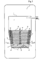
- Figure 1 schematically illustrates a view of a pressurized fluidized bed where the positions of the defluidizing devices according to the invention are shown.
- Figure 2 shows the same view as Figure 1 with regions where non-fluidized zones are created between the tube bundle and the boiler wall by means of devices according to the invention marked as regions in the figure with heavier shading.
- Figure 3 schematically shows a view of a pressurized fluidized bed where the positions of the defluidizing devices according to the invention are shown in a bed where two tube bundles create an intermediate gap and where a non-fluidized zone is created between two tube bundles by means of devices according to the invention, the non-fluidized region being marked in the figure as a region with heavier shading in the gap created between the tube bundles.
- Figure 1 the central units of a PFBC power plant are represented, wherein a combustor 1 is housed in a pressure vessel 2. Air from a compressor (not shown) is supplied to the pressure vessel 2 via the air inlet 3 for pressurization of the pressure vessel 2 and hence also the combustor 1. The compressed air 4 is supplied to the combustor 1 via fluidization nozzles 5 at the bottom of the combustor for fluidization of a bed 6 accommodated in the combustor.
- the bed consists of bed material and of particulate fuel which is burnt in the fluidizing air 4 supplied to the bed 6.
- Combustion gases from the bed 6 pass through a freeboard above the surface of the bed and are forwarded via the outlet 8 for cleaning in dust separators, whereafter the combustion gases are expanded in a gas turbine (not shown), where the energy contents in the gases are transformed into useful energy.
- a tube bundle 10 which is completely immersed into the bed at full-load operation, is also shown. Water is supplied to the tube bundle 10 at 11 for cooling the bed 10 and further for generating steam in the tubes in the tube bundle. The steam is forwarded at 12 to a steam turbine (not shown) in a steam cycle in the plant.
- the heat-transfer area of the tubes in the tube bundle 10 is made somewhat larger than what is justified to achieve a cooling of the bed which is sufficient to maintain the bed at an optimum working temperature.
- the heat-transfer area of the tubes of the tube bundle 10 can then be reduced by installing a barrier or shield in the form of - in the simplest case - a shelf 15 near the lowermost level 14 of the tube bundle.
- the shelf is suitably located horizontally or almost horizontally and is connected to the boiler wall 16, that is, in this case to the wall of the combustor 1 and will thus block the inlet for a flow of fluidized bed material to a gap 17 shown between the tube bundle 10 and the boiler wall 16.
- an almost vertical channel 18 of non-fluidized bed material thus arises along the boiler wall 16.
- the shelf 15 consists of a plate which is attached to the boiler wall 16, for example by welding thereto.
- Other materials and other forms than a plate shelf plane may, of course, be used.
- other geometries of the barrier may be desirable. For example, shapes with triangular cross sections may be preferable.
- a defluidizing member 15 instead of a shelf 15 there may be arranged a low, preferably vertical, fixedly mounted partition which is applied near the lowermost tubes of the tube system (10), between the gap 17 and the tube system 10, while at the same time fluidizing air is not supplied below the gap 17 in the bed.
- a low, preferably vertical, fixedly mounted partition which is applied near the lowermost tubes of the tube system (10), between the gap 17 and the tube system 10, while at the same time fluidizing air is not supplied below the gap 17 in the bed.
Landscapes
- Engineering & Computer Science (AREA)
- Chemical & Material Sciences (AREA)
- Combustion & Propulsion (AREA)
- Mechanical Engineering (AREA)
- General Engineering & Computer Science (AREA)
- Physics & Mathematics (AREA)
- Thermal Sciences (AREA)
- Fluidized-Bed Combustion And Resonant Combustion (AREA)
- Heat-Exchange Devices With Radiators And Conduit Assemblies (AREA)
Description
- A PFBC power plant (Pressurized Fluidized Bed Combustion) is provided with a steam turbine for utilizing steam energy generated in a tube system immersed into a fluidized bed. A gas turbine is employed at the same time for utilizing the energy contents in flue gases formed during combustion in the bed. The invention relates to the problem of dimensioning the heat-transferring tube area of the tube system.
- During combustion of particulate fuel, usually coal, in a pressurized fluidized bed of a PFBC power plant, the bed is supplied with combustion air in the form of compressed air from the pressure vessel which surrounds a bed vessel, wherein the fluidized bed is stored, via fluidization nozzles below the bed. The combustion gases which are formed during the combustion process are passed through a freeboard above the bed surface, whereupon they are cleaned and passed to a gas turbine. The combustion gases drive the gas turbine, which in turn drive a generator as well as a compressor which provides the pressure vessel with compressed air.
- For cooling the bed to a temperature of the order of magnitude of 850°C, a steam generator in the form of a tube bundle, which constitutes a component in a steam system, is placed in the bed. In the tube bundle steam is generated, energy thus being obtained from the bed via the steam turbines to which the steam is led in the steam system. At full load, the entire tube bundle is situated within the bed. The cooling capacity of the tube bundle must be dimensioned to the power output from the bed to be able to maintain the correct bed temperature. At full load output from the plant, it is desired that both the steam turbine and the gas turbine are supplied with nominal power values for the respective turbine type, dimensioned for the plant. On the other hand, it is a difficult technical problem to dimension the steam turbine to the exactly nominally correct power value when designing a PFBC plant, that is, the design of the steam turbine. The dimensioning of the steam turbine is dependent on the fuel fineness, the moisture content of the fuel, the type of fuel, etc., whereby the dimensioning of the steam turbine entails an adaptation to each individual plant taking into consideration, inter alia, the properties of the fuel. A fundamental and difficult question to answer is how large a heat-transfer area is required in the tube bundle to achieve a certain desired steam production. At full load, the heat transfer to the tube bundle shall be designed such that the calculated desired nominal temperature of the combustion gases, which are to drive the gas turbine, at full bed height at the same time provides a nominal steam production in the tube bundle such that a 100 per cent power output from the gas turbine is obtained while at the same time a 100 per cent power output is obtained at the steam turbine.
- The heat absorption in the bed is performed by the generation of steam in the steam generator shaped as a tube bundle. The steam production is controlled by the relationship
- Q is the transferred quantity of heat
- ΔT is the locally driving temperature difference
- A is the installed area of the steam generator
- k is the heat-transfer coefficient
-
- For the steam cycle in a PFBC power plant, the temperature difference cannot be freely influenced. The reason for this resides in factors associated with combustion engineering and especially environmental factors.
- A constitutes the installed area of the steam generator in the PFBC plant and cannot be influenced without interfering in the plant.
- The third parameter k can be influenced to a certain extent. However, it must be pointed out that the parameter k or that part of the parameter k which is related to the external heat-transfer coefficient is - from the engineering point of view - a difficult parameter to calculate with satisfactory accuracy and thus to take into account when dimensioning the steam generator. This means that when designing the steam generator for a PFBC plant, a certain inaccuracy in the area dimensioning must be accepted. In addition, the dimensioning of the steam generator requires that variation in the steam production due to, for example, the quality of the fuel is taken into consideration.
- Another problem which should be observed is the uncertainty which arises because of the properties of the bed, over which technicians have moderate control. This includes, for example, variation of particle fineness or particle properties when the quality or composition of the fuel fluctuates, or when changing to firing of a somewhat different type of coal than what was originally intended when firing, for example, particulate coal, all of these examples resulting in a changed k-value with an ensuing incorrectly dimensioned heat transfer.
- When adjusting a correct heat-transfer area in a fluidized bed, it has previously been necessary to increase or reduce the already-installed tube area, when it is found afterwards that the tube area is inaccurately dimensioned. This is costly.
- Another way of solving the problem with dimensioning of the tube area of the tube system is disclosed in SE 91018820. According to this publication, the heat-transfer area of the steam generator is designed somewhat oversized in the bed of a PFBC power plant. In this way, a surplus of steam is generated in the steam system of the power plant. The surplus steam is discharged from the steam system downstream of the bed and is supplied to a preheater in the form of a heat exchanger, which the combustion air flows through upstream of the bed, a higher temperature thus being imparted to the combustion air included, which results in the power output from the gas turbine increasing. In this connection, an incorrectly dimensioned tube system may be corrected by transferring a variable quantity of energy to a gas system in which the gas turbine is included. A disadvantage of such a solution is that it entails installation of additional components and associated control equipment and thus makes the plant more complicated.
- US-A-3 542 523 describes a fluidized bed combustion system comprising a number of peripheral pockets each having its own heat exchanger and air supply. The air supply can be individually activated or deactivated to control the cooling capacity.
- The present invention is defined in
claims - Defluidization is achieved in a very simple manner by shutting off the fluidizing air to the bed below a vertical channel where a defluidized zone is to be created. A barrier in the form of a shelf or a stop plate is installed near the lowermost level of the tube bundle, thus preventing fluidizing air from reaching the bed above the barrier. This results in the creation of an almost vertically standing defluidized zone above the barrier. The cross-section area of the zone in the horizontal direction is determined by the horizontal area of the barrier.
- In the non-fluidized zones, no significant combustion takes place, since no, or a very limited, particle movement occurs. No, or very little, power is thus absorbed by tubes disposed in these non-fluidized zones. Tube surfaces which, by the actions described according to the invention, end up in non-fluidized zones will thereby not be heat-transfer areas. By creating non-fluidized zones with an adapted area, the too large heat-transfer area of the tube system may be compensated for by means of non-fluidized zones in the bed.
- Most appropriately, these defluidized zones are created nearest the walls of the combustor by shutting off the fluidizing air as mentioned above and installing stop plates at the boiler walls in the vicinity of the lower level of a tube bundle.
- Some of the advantages of readjusting the heat-transfer area of the tube system according to the invention are the following:
- the non-fluidized zones are achieved in a very simple manner, as already mentioned, for example by installing stop plates according to the embodiments,
- the extent of the defluidization and the reduction of the heat-transfer area, dependent thereon, of the tube system can be easily changed, and
- the actions described can be realized at low costs.
- An additional advantage of the invention is that the risks of erosion on tube surfaces and boiler walls are reduced. Experience has shown a tendency to erosion in vertical channels in a fluidized wall, where no obstacles to a bed material flow in the vertical direction occur, as is the case precisely at a gap between tubes in a tube bundle and an adjacent boiler wall. The upwardly-rising flows of fluidizing gas and the flows of bed material may in these gaps reach high velocities, which results in a higher erosion effect on the wall and tube material close to the path of the flow. By placing the defluidized barriers according to the invention, for example in the form of stop plates, at the boiler walls near the lower level of the tube system, the occurrence of erosion-promoting gaps is prevented between tubes and boiler wall.
- Still another advantage of the method according to the invention can be understood when considering the construction of the walls in the room which surrounds the bed. These walls consist of tube panels, which at the same time constitute a part of the walls of the combustor. These tube panels are traversed by water, included in the steam system of the plant. The water is usually heated in an economizer and is thereafter preheated further in the tube panels around the bed before the water is supplied to a steam generator in the bed. From the point of view of manufacturing, it is an advantage to be able to heat the water in the economizer to a high degree. If the heating is driven too far in the economizer, on the other hand, a risk of boiling of the water in the panel walls of the combustor arises. To overcome this problem, it has previously been necessary to insulate the walls of the bed in the combustor, for example by means of ceramics, to prevent too much heat from being transferred from the bed to the water in the tube panels around the bed. With the method according to the invention, an insulating layer is achieved by means of the non-fluidized zones along the walls of the bed, which layer provides the same effect as the above-mentioned installed extra ceramic insulation on the insides of the bed walls. If desired, this extra insulation may be excluded.
- Figure 1 schematically illustrates a view of a pressurized fluidized bed where the positions of the defluidizing devices according to the invention are shown.
- Figure 2 shows the same view as Figure 1 with regions where non-fluidized zones are created between the tube bundle and the boiler wall by means of devices according to the invention marked as regions in the figure with heavier shading.
- Figure 3 schematically shows a view of a pressurized fluidized bed where the positions of the defluidizing devices according to the invention are shown in a bed where two tube bundles create an intermediate gap and where a non-fluidized zone is created between two tube bundles by means of devices according to the invention, the non-fluidized region being marked in the figure as a region with heavier shading in the gap created between the tube bundles.
- A number of embodiments of the invention will be described with reference to the accompanying drawings.
- In an overall figure (Figure 1), the central units of a PFBC power plant are represented, wherein a
combustor 1 is housed in apressure vessel 2. Air from a compressor (not shown) is supplied to thepressure vessel 2 via theair inlet 3 for pressurization of thepressure vessel 2 and hence also thecombustor 1. The compressed air 4 is supplied to thecombustor 1 via fluidization nozzles 5 at the bottom of the combustor for fluidization of abed 6 accommodated in the combustor. The bed consists of bed material and of particulate fuel which is burnt in the fluidizing air 4 supplied to thebed 6. Combustion gases from thebed 6 pass through a freeboard above the surface of the bed and are forwarded via theoutlet 8 for cleaning in dust separators, whereafter the combustion gases are expanded in a gas turbine (not shown), where the energy contents in the gases are transformed into useful energy. - In the
fluidized bed 6, atube bundle 10, which is completely immersed into the bed at full-load operation, is also shown. Water is supplied to thetube bundle 10 at 11 for cooling thebed 10 and further for generating steam in the tubes in the tube bundle. The steam is forwarded at 12 to a steam turbine (not shown) in a steam cycle in the plant. - According to the invention, the heat-transfer area of the tubes in the
tube bundle 10 is made somewhat larger than what is justified to achieve a cooling of the bed which is sufficient to maintain the bed at an optimum working temperature. - According to the invention, the heat-transfer area of the tubes of the
tube bundle 10 can then be reduced by installing a barrier or shield in the form of - in the simplest case - ashelf 15 near thelowermost level 14 of the tube bundle. The shelf is suitably located horizontally or almost horizontally and is connected to theboiler wall 16, that is, in this case to the wall of thecombustor 1 and will thus block the inlet for a flow of fluidized bed material to agap 17 shown between thetube bundle 10 and theboiler wall 16. As illustrated in Figure 2, an almostvertical channel 18 of non-fluidized bed material thus arises along theboiler wall 16. In thischannel 18 no significant combustion takes place, since no transfer of fuel to the non-fluidized region takes place, which means that the tube surfaces which are situated within the verticalnon-fluidized channel 18 will not function as heat-transfer areas to any significant extent. In this way, a reduction of an actively heat-transferring area in the tube bundle is achieved. The reduction of this heat-transfer area of thetube bundle 10 may then be chosen by means of adaptation of the area of theshelf 15 which shields off the region above the shelf from access to fluidizing air and thus creates anon-fluidized channel 18 of the desired magnitude. - To improve the function of the shielding by means of the
shelf 15, the supply of fluidizing air 4 tofluidization nozzles 19, located below theshelf 15, is shut off. - In the simplest case, the
shelf 15 consists of a plate which is attached to theboiler wall 16, for example by welding thereto. Other materials and other forms than a plate shelf plane may, of course, be used. For reasons of flow characteristics, other geometries of the barrier may be desirable. For example, shapes with triangular cross sections may be preferable. - In those cases where more than one
tube bundle 10 occurs in acombustor 1, it may be justified to create defluidized zones in a similar manner as above in vertical gaps which occur between the various tube bundles. In this case, ashelf 15 is installed in a corresponding manner below the gap which occurs between two tube bundles. This leads to the creation of anon-fluidized zone 18 in the gap between the adjacent tube bundles. - In another, alternative embodiment of a
defluidizing member 15, instead of ashelf 15 there may be arranged a low, preferably vertical, fixedly mounted partition which is applied near the lowermost tubes of the tube system (10), between thegap 17 and thetube system 10, while at the same time fluidizing air is not supplied below thegap 17 in the bed. Through this arrangement, non-fluidized ash and bed material will accumulate in a pocket between the partition and theboiler wall 16, whereby the accumulated material will serve as a defluidizing shelf similar to theshelf 15 described above.
Claims (10)
- A method for adjusting the heat-transferring tube area in an oversized tube system (10) immersed into a fluidizing bed (6) in a power plant which comprises a combustor (1) with a fluidized bed (6) enclosed therein, wherein a fuel is burnt, where the bed is fluidized by means of air (4) which is supplied to the bottom of the bed via nozzles (5) and where the bed is cooled by means of a coolant which traverses the tube system (10), characterized in that the heat-transfer area of the tube system (10) is reduced to an optimum level by arranging, at the lowermost level of the tube system (10), fixedly mounted barrier members (15) which constantly prevent fluidization of the bed (6) in non-fluidized, essentially vertical channels (18) downstream of the barrier member (15), whereby the tube surfaces which are located within the non-fluidized channel (18) are not supplied with any heat and are thus made passive from the point of view of heat transfer.
- A method according to claim 1, characterized in that the barrier members (15) are in the form of shelves or plates, wherein the cross-section area of the vertical non-fluidized channels (18), and hence the reduction of the heat-transfer area of the tube system, are determined by the area of the fluidization-preventing barrier members (15).
- A method according to claim 2, characterized in that fluidizing air to the bed (6) is shut off at fluidization nozzles (19) located upstream of the fluidization-preventing barrier members (15).
- A fluidized bed combustor (1) comprising means for adjusting the heat-transferring tube area in an oversized tube system (10) immersed into a fluidizing bed (6), wherein a fuel is burnt, enclosed in said combustor (1), wherein the bed is fluidized by means of air (4) which is supplied to the bottom at the bed via nozzles (5) and where the bed is cooled by means of a coolant which traverses the tube system (10), characterized in that said means for adjusting the heat-transferring tube area comprises barrier members (15) fixedly mounted at the lowermost level of the tube system (10), said barrier members constantly preventing fluidization of the bed (6) in non-fluidized, essentially vertical channels (18) downstream of the barrier member (15), whereby the tube surfaces which are located within the non-fluidized channel (18) are not supplied with any heat and are then made passive from the point of view of heat transfer, such that the heat-transfer area of the tube system (10) is reduced to an optimum level by means of said barrier members (15).
- A fluidized bed combustor (1) according to claim 4, characterized in that the fluidization-preventing barrier member (15) consists of a shield or shelf which is applied essentially horizontally at the lowermost level of the tube system (10).
- A fluidized bed combustor (1) according to claim 5, characterized in that the barrier member (15) is applied against the boiler wall (16) and hence creates a non-fluidized channel (18) in a gap (17) exhibited between the tube system (10) and the boiler wall (16).
- A fluidized bed combustor (1) according to claim 5, characterized in that the barrier member (15) is applied essentially horizontally at the lowermost level of the tube system (10) at the gap which occurs between two tube bundles in the tube system (10) and hence creates a non-fluidized channel (18) in said gap.
- A fluidized bed combustor (1) according to any of the claims 4-7, characterized in that the fluidization-preventing barrier member (15) consists of a plate.
- A method for adjusting the heat-transferring tube area in an oversized tube system (10) immersed into a fluidizing bed (6) in a power plant which comprises a combustor (1) with a fluidized bed (6) enclosed therein, wherein a fuel is burnt, where the bed is fluidized by means of air (4) which is supplied to the bottom of the bed via nozzles (5) and where the bed is cooled by means of a coolant which traverses the tube system (10), characterized in that the heat-transfer area of the tube system (10) is reduced to an optimum level by arranging, at the lowermost level of the tube system (10), a fixedly mounted essentially vertically arranged partition, and by blocking the supply of air in the area between the partition and a wall (16) of the combustor (1), such that fluidization of the bed (6) is constantly prevented in non-fluidized, essentially vertical channels (18) downstream of said area between the partition and the wall, whereby the tube surfaces which are located within the non-fluidized channel (18) are not supplied with any heat and are thus made passive from the point of view of heat transfer.
- A fluidized bed combustor (1) comprising means for adjusting the heat-transferring tube area in an oversized system (10) immersed into a fluidizing bed (6), wherein a fuel is burnt, enclosed in said combustor (1), wherein the bed is fluidized by means of air (4) which is supplied to the bottom at the bed via nozzles (5) and where the bed is cooled by means of a coolant which traverses the tube system (10), characterized in that said means for adjusting the heat-transferring tube area comprises an essentially vertically arranged partition, fixedly mounted at the lowermost level of the tube system (10), wherein the air supply is arranged such that the supply of air is blocked in the area between the partition and a wall (16) of the combustor (1), such that fluidization of the bed (6) is constantly prevented in non-fluidized, essentially vertical channels (18) downstream of the area between the partition and the wall (16), whereby the tube surfaces which are located within the non-fluidized channel (18) are not supplied with any heat and are then made passive from the point of view of heat transfer, such that the heat-transfer area of the tube system (10) is reduced to an optimum level.
Applications Claiming Priority (3)
| Application Number | Priority Date | Filing Date | Title |
|---|---|---|---|
| SE9401032 | 1994-03-28 | ||
| SE9401032A SE9401032L (en) | 1994-03-28 | 1994-03-28 | Method and apparatus for adjusting the tube surface in a fluidized bed |
| PCT/SE1995/000322 WO1995026483A1 (en) | 1994-03-28 | 1995-03-27 | Method and device for readjusting the heat transfer surface of a fluidized bed |
Publications (2)
| Publication Number | Publication Date |
|---|---|
| EP0795108A1 EP0795108A1 (en) | 1997-09-17 |
| EP0795108B1 true EP0795108B1 (en) | 1999-10-27 |
Family
ID=20393443
Family Applications (1)
| Application Number | Title | Priority Date | Filing Date |
|---|---|---|---|
| EP95914650A Expired - Lifetime EP0795108B1 (en) | 1994-03-28 | 1995-03-27 | Method and device for readjusting the heat transfer surface of a fluidized bed |
Country Status (6)
| Country | Link |
|---|---|
| EP (1) | EP0795108B1 (en) |
| DE (1) | DE69513039T2 (en) |
| ES (1) | ES2141345T3 (en) |
| FI (1) | FI970559A7 (en) |
| SE (1) | SE9401032L (en) |
| WO (1) | WO1995026483A1 (en) |
Families Citing this family (2)
| Publication number | Priority date | Publication date | Assignee | Title |
|---|---|---|---|---|
| FI118977B (en) | 1999-01-21 | 2008-05-30 | Metso Power Oy | Procedure in conjunction with the floating bed boiler and beam grate |
| DE102016225338A1 (en) * | 2016-12-16 | 2018-06-21 | Deutsches Zentrum für Luft- und Raumfahrt e.V. | Heat exchanger for heat transfer between a particulate heat transfer medium and a second medium |
Family Cites Families (10)
| Publication number | Priority date | Publication date | Assignee | Title |
|---|---|---|---|---|
| US2842102A (en) * | 1954-11-18 | 1958-07-08 | Combustion Eng | Steam generation |
| US3387590A (en) * | 1967-03-16 | 1968-06-11 | Interior Usa | System for regulating the total heat output in a burning fluidized bed heat exchanger or boiler |
| US3542523A (en) * | 1967-09-08 | 1970-11-24 | Dorr Oliver Inc | Reactor design |
| GB1525222A (en) * | 1973-05-05 | 1978-09-20 | Pearce A | Fluidised beds |
| US4177765A (en) * | 1978-08-14 | 1979-12-11 | The Babcock & Wilcox Co. | Output control for fluidized bed boilers |
| DE3030215A1 (en) * | 1980-08-09 | 1982-03-18 | Bergwerksverband Gmbh, 4300 Essen | Fluid bed firing |
| US4396056A (en) * | 1980-11-19 | 1983-08-02 | Hodges James L | Apparatus and method for controlling heat transfer between a fluidized bed and tubes immersed therein |
| US4436507A (en) * | 1981-07-16 | 1984-03-13 | Foster Wheeler Energy Corporation | Fluidized bed reactor utilizing zonal fluidization and anti-mounding air distributors |
| US4453494A (en) * | 1982-03-22 | 1984-06-12 | Combustion Engineering, Inc. | Fluidized bed boiler having a segmented grate |
| SE457661B (en) * | 1986-06-12 | 1989-01-16 | Lars Axel Chambert | SEAT AND REACTOR FOR FLUIDIZED BOTTOM |
-
1994
- 1994-03-28 SE SE9401032A patent/SE9401032L/en not_active Application Discontinuation
-
1995
- 1995-03-27 DE DE69513039T patent/DE69513039T2/en not_active Expired - Fee Related
- 1995-03-27 EP EP95914650A patent/EP0795108B1/en not_active Expired - Lifetime
- 1995-03-27 ES ES95914650T patent/ES2141345T3/en not_active Expired - Lifetime
- 1995-03-27 WO PCT/SE1995/000322 patent/WO1995026483A1/en not_active Ceased
-
1997
- 1997-02-10 FI FI970559A patent/FI970559A7/en active IP Right Revival
Also Published As
| Publication number | Publication date |
|---|---|
| SE9401032L (en) | 1995-09-29 |
| ES2141345T3 (en) | 2000-03-16 |
| FI970559A0 (en) | 1997-02-10 |
| FI970559A7 (en) | 1997-02-10 |
| WO1995026483A1 (en) | 1995-10-05 |
| DE69513039D1 (en) | 1999-12-02 |
| EP0795108A1 (en) | 1997-09-17 |
| DE69513039T2 (en) | 2000-06-29 |
| SE9401032D0 (en) | 1994-03-28 |
Similar Documents
| Publication | Publication Date | Title |
|---|---|---|
| EP0574176B1 (en) | Fluidized bed reactor system and method having a heat exchanger | |
| US8511258B2 (en) | Coal boiler and coal boiler combustion method | |
| EP1847773B1 (en) | Integrated fluidized bed ash cooler | |
| RU2104442C1 (en) | Circulating fluidized bed reactor | |
| CN101398167B (en) | Black plant steam furnace injection | |
| US5950574A (en) | Boiler | |
| FI91220B (en) | Method and apparatus for implementing a gas trap in a return pipe and / or for controlling the flow of circulating material in a circulating fluidized bed reactor | |
| RU2627866C2 (en) | Valve for controlling solid phase in fluidized layer with high reliability | |
| JPS5837402A (en) | Boiler | |
| EP0457839A1 (en) | A power plant with combustion of a fuel in a fluidized bed. | |
| EP0795108A1 (en) | Method and device for readjusting the heat transfer surface of a fluidized bed | |
| KR19990071571A (en) | Circulating fluidized bed reactor with multiple furnace outlets | |
| EP0214538B1 (en) | Power plant with a fluidized bed combustion chamber | |
| EP3877697B1 (en) | A combustor air bar grid for use within a fluidized bed reactor, and a fluidized bed reactor | |
| WO2015090636A1 (en) | Fluidized bed apparatus and its components | |
| EP1149257B1 (en) | Pipe grate for a fluidized bed boiler | |
| KR102807969B1 (en) | Circulating fluidized bed boiler | |
| EP0536967A2 (en) | Protection system for heat pipe airheaters | |
| JPS58214701A (en) | Fluidized-bed heat exchanger to which baffle plate device is arranged | |
| JPH07284654A (en) | Fluid cooling jacket | |
| EA000099B1 (en) | Steam generator with supercharged circulating fluidized bed combustion | |
| Goidich et al. | The pressurized combustor | |
| COMBUSTOR et al. | GENERAL mELECTRIC | |
| Robertson et al. | Pressurized fluidized bed combustion second-generation system research and development | |
| UA45473C2 (en) | WATER HEATING BOILER |
Legal Events
| Date | Code | Title | Description |
|---|---|---|---|
| PUAI | Public reference made under article 153(3) epc to a published international application that has entered the european phase |
Free format text: ORIGINAL CODE: 0009012 |
|
| 17P | Request for examination filed |
Effective date: 19970111 |
|
| AK | Designated contracting states |
Kind code of ref document: A1 Designated state(s): DE ES FR GB IT |
|
| 17Q | First examination report despatched |
Effective date: 19980715 |
|
| GRAG | Despatch of communication of intention to grant |
Free format text: ORIGINAL CODE: EPIDOS AGRA |
|
| GRAG | Despatch of communication of intention to grant |
Free format text: ORIGINAL CODE: EPIDOS AGRA |
|
| GRAH | Despatch of communication of intention to grant a patent |
Free format text: ORIGINAL CODE: EPIDOS IGRA |
|
| GRAH | Despatch of communication of intention to grant a patent |
Free format text: ORIGINAL CODE: EPIDOS IGRA |
|
| GRAA | (expected) grant |
Free format text: ORIGINAL CODE: 0009210 |
|
| AK | Designated contracting states |
Kind code of ref document: B1 Designated state(s): DE ES FR GB IT |
|
| REF | Corresponds to: |
Ref document number: 69513039 Country of ref document: DE Date of ref document: 19991202 |
|
| PGFP | Annual fee paid to national office [announced via postgrant information from national office to epo] |
Ref country code: DE Payment date: 19991231 Year of fee payment: 6 |
|
| ITF | It: translation for a ep patent filed | ||
| ET | Fr: translation filed | ||
| PGFP | Annual fee paid to national office [announced via postgrant information from national office to epo] |
Ref country code: FR Payment date: 20000310 Year of fee payment: 6 |
|
| REG | Reference to a national code |
Ref country code: ES Ref legal event code: FG2A Ref document number: 2141345 Country of ref document: ES Kind code of ref document: T3 |
|
| PGFP | Annual fee paid to national office [announced via postgrant information from national office to epo] |
Ref country code: GB Payment date: 20000322 Year of fee payment: 6 Ref country code: ES Payment date: 20000322 Year of fee payment: 6 |
|
| PLBE | No opposition filed within time limit |
Free format text: ORIGINAL CODE: 0009261 |
|
| STAA | Information on the status of an ep patent application or granted ep patent |
Free format text: STATUS: NO OPPOSITION FILED WITHIN TIME LIMIT |
|
| 26N | No opposition filed | ||
| PG25 | Lapsed in a contracting state [announced via postgrant information from national office to epo] |
Ref country code: GB Free format text: LAPSE BECAUSE OF NON-PAYMENT OF DUE FEES Effective date: 20010327 |
|
| PG25 | Lapsed in a contracting state [announced via postgrant information from national office to epo] |
Ref country code: ES Free format text: LAPSE BECAUSE OF NON-PAYMENT OF DUE FEES Effective date: 20010328 |
|
| GBPC | Gb: european patent ceased through non-payment of renewal fee |
Effective date: 20010327 |
|
| PG25 | Lapsed in a contracting state [announced via postgrant information from national office to epo] |
Ref country code: FR Free format text: LAPSE BECAUSE OF NON-PAYMENT OF DUE FEES Effective date: 20011130 |
|
| REG | Reference to a national code |
Ref country code: FR Ref legal event code: ST |
|
| PG25 | Lapsed in a contracting state [announced via postgrant information from national office to epo] |
Ref country code: DE Free format text: LAPSE BECAUSE OF NON-PAYMENT OF DUE FEES Effective date: 20020101 |
|
| REG | Reference to a national code |
Ref country code: ES Ref legal event code: FD2A Effective date: 20030303 |
|
| PG25 | Lapsed in a contracting state [announced via postgrant information from national office to epo] |
Ref country code: IT Free format text: LAPSE BECAUSE OF NON-PAYMENT OF DUE FEES Effective date: 20050327 |