EP0794807B1 - Artificial airway device - Google Patents
Artificial airway device Download PDFInfo
- Publication number
- EP0794807B1 EP0794807B1 EP96932711A EP96932711A EP0794807B1 EP 0794807 B1 EP0794807 B1 EP 0794807B1 EP 96932711 A EP96932711 A EP 96932711A EP 96932711 A EP96932711 A EP 96932711A EP 0794807 B1 EP0794807 B1 EP 0794807B1
- Authority
- EP
- European Patent Office
- Prior art keywords
- mask
- tube
- tubular conduit
- ring
- inflatable
- Prior art date
- Legal status (The legal status is an assumption and is not a legal conclusion. Google has not performed a legal analysis and makes no representation as to the accuracy of the status listed.)
- Expired - Lifetime
Links
Images

Classifications
-
- A—HUMAN NECESSITIES
- A61—MEDICAL OR VETERINARY SCIENCE; HYGIENE
- A61M—DEVICES FOR INTRODUCING MEDIA INTO, OR ONTO, THE BODY; DEVICES FOR TRANSDUCING BODY MEDIA OR FOR TAKING MEDIA FROM THE BODY; DEVICES FOR PRODUCING OR ENDING SLEEP OR STUPOR
- A61M16/00—Devices for influencing the respiratory system of patients by gas treatment, e.g. mouth-to-mouth respiration; Tracheal tubes
- A61M16/04—Tracheal tubes
- A61M16/0402—Special features for tracheal tubes not otherwise provided for
- A61M16/0409—Special features for tracheal tubes not otherwise provided for with mean for closing the oesophagus
-
- A—HUMAN NECESSITIES
- A61—MEDICAL OR VETERINARY SCIENCE; HYGIENE
- A61M—DEVICES FOR INTRODUCING MEDIA INTO, OR ONTO, THE BODY; DEVICES FOR TRANSDUCING BODY MEDIA OR FOR TAKING MEDIA FROM THE BODY; DEVICES FOR PRODUCING OR ENDING SLEEP OR STUPOR
- A61M16/00—Devices for influencing the respiratory system of patients by gas treatment, e.g. mouth-to-mouth respiration; Tracheal tubes
- A61M16/04—Tracheal tubes
- A61M16/0402—Special features for tracheal tubes not otherwise provided for
- A61M16/0415—Special features for tracheal tubes not otherwise provided for with access means to the stomach
-
- A—HUMAN NECESSITIES
- A61—MEDICAL OR VETERINARY SCIENCE; HYGIENE
- A61M—DEVICES FOR INTRODUCING MEDIA INTO, OR ONTO, THE BODY; DEVICES FOR TRANSDUCING BODY MEDIA OR FOR TAKING MEDIA FROM THE BODY; DEVICES FOR PRODUCING OR ENDING SLEEP OR STUPOR
- A61M16/00—Devices for influencing the respiratory system of patients by gas treatment, e.g. mouth-to-mouth respiration; Tracheal tubes
- A61M16/04—Tracheal tubes
- A61M16/0434—Cuffs
- A61M16/0445—Special cuff forms, e.g. undulated
-
- A—HUMAN NECESSITIES
- A61—MEDICAL OR VETERINARY SCIENCE; HYGIENE
- A61M—DEVICES FOR INTRODUCING MEDIA INTO, OR ONTO, THE BODY; DEVICES FOR TRANSDUCING BODY MEDIA OR FOR TAKING MEDIA FROM THE BODY; DEVICES FOR PRODUCING OR ENDING SLEEP OR STUPOR
- A61M16/00—Devices for influencing the respiratory system of patients by gas treatment, e.g. mouth-to-mouth respiration; Tracheal tubes
- A61M16/04—Tracheal tubes
- A61M16/0434—Cuffs
- A61M16/0454—Redundant cuffs
- A61M16/0456—Redundant cuffs one cuff within another
-
- A—HUMAN NECESSITIES
- A61—MEDICAL OR VETERINARY SCIENCE; HYGIENE
- A61M—DEVICES FOR INTRODUCING MEDIA INTO, OR ONTO, THE BODY; DEVICES FOR TRANSDUCING BODY MEDIA OR FOR TAKING MEDIA FROM THE BODY; DEVICES FOR PRODUCING OR ENDING SLEEP OR STUPOR
- A61M16/00—Devices for influencing the respiratory system of patients by gas treatment, e.g. mouth-to-mouth respiration; Tracheal tubes
- A61M16/04—Tracheal tubes
- A61M16/0434—Cuffs
- A61M16/0454—Redundant cuffs
- A61M16/0459—Redundant cuffs one cuff behind another
Definitions
- This invention relates to a laryngeal-mask airway (LMA) device, which is an artificial airway device designed to facilitate lung ventilation in an unconscious patient by forming a low-pressure seal around the laryngeal inlet.
- An inflatable-ring seal surrounds an appropriately shaped mask which fits into the lower pharynx and is attached to a tube which emerges from the mouth, as for connection to medical gas-supply tubing.
- the invention relates to a variety of laryngeal masks, known as gastro-laryngeal masks (GLM), wherein provision is made for airway assurance to the patient who is at risk from vomiting or regurgitation of stomach contents while unconscious.
- GLM gastro-laryngeal masks
- U.S. Patent 5,241,956 deals with this problem by providing an evacuation tube which is open through the center of the inflatable seal of the laryngeal mask, thus utilizing the distal end of the inflatable ring as an inflatable-cuff formation which establishes peripherally sealed engagement to the upper sphinctral region of the oesophagus and centrally supports the distal end of the evacuation tube.
- Patent 5,241,956 discloses a further inflatable cuff carried by the laryngeal mask and by the evacuation tube, for referencing inflation against the back wall of the pharynx, thus making it possible to establish the laryngeal-inlet seal with reduced inflation pressure, as compared with prior structures not having such an additional inflatable cuff.
- U.S. Patent 5,305,743 discloses moulding techniques for manufacture of a variety of laryngeal masks, including a gastro-laryngeal mask, wherein an inflatable back cushion provides such referencing inflation against the back wall of the pharynx as to widely distribute the back-wall reference, over substantially the full area of the laryngeal mask.
- an inflatable back cushion provides such referencing inflation against the back wall of the pharynx as to widely distribute the back-wall reference, over substantially the full area of the laryngeal mask.
- Such a back-cushion construction has been found to be mechanically simple and highly effective, and U.S. Patent 5,355,879 discloses such a back cushion for each of several representative laryngeal-mask constructions.
- Provision of a pre-curved airway tube facilitates passage around the back of the tongue, but the advancing distal tip end of the device is then more likely to collide with the glottis (or entrance to the larynx), and indeed it may block the larynx by so doing, with consequent danger to the patient.
- the present invention seeks to provide a laryngeal mask construction that specifically avoids the problems and difficulties encountered with the devices of the above U.S. patents and especially of U.S. Patent 5,355,879 by allowing for ready compression and flexure of a gastric passage within a back-cushioned or cuffed gastro-laryngeal mask when the mask is in deflated condition for insertion into the patient's throat.
- Such a construction has been found to enable formation of a flattened flexible leading distal-end edge to self-adapt to and resiliently ride the outer limit of curvature of the patient's airway, throughout the insertional course of the deflated mask and into its locating engagement with the hypopharynx, and to provide for assurance of full patency of the gastric passage within the mask, when the mask has been inflated.
- a laryngeal mask airway device comprising a generally elliptical inflatable ring of relatively thin and softly pliant molded elastomeric material, having an outer periphery adapted for sealed engagement to the laryngeal inlet and including within its inner periphery an apertured panel separating its pharyngeal and laryngeal sides, the ring extending longitudinally between proximal and distal ends and having an inflation port connection at its proximal end, the ring further including at its distal end an open tubular conduit for operative engagement and communication with the oesophageal inlet, the tubular conduit extending from its distally open end proximally on the pharyngeal side of the panel; a domed backing-plate of relatively stiff material having a concave side terminating in a generally elliptical footing in a geometric plane and sealed around the aperture in the panel at the inner periphery of the elliptical ring
- an artificial airway device to facilitate a patient's lung ventilation comprises an airway tube, an evacuation tube, and a laryngeal mask at one end of both tubes.
- the mask is of generally elliptical configuration and comprises a body or backplate of relatively stiffly compliant nature, and an inflatable annular cuff or ring of relatively softly compliant nature is connected to and surrounds the body or backplate.
- the annular cuff When inflated, the annular cuff adapts to and seals around the laryngeal inlet, and an inflatable cushion on the exterior of the inflated annulus bears against the back wall of the pharynx, to thereby forwardly load the inflated annulus into sealed relation with the laryngeal inlet, with the backplate dividing the mask between a laryngeal-chamber side and a pharyngeal-chamber side.
- the relatively stiff backplate is formed for connection to the airway tube for exclusive communication to the larynx through an opening in the backplate; and the backplate is also, configured to guide and support a relatively soft flexible evacuation tube within the pharyngeal-chamber side, from a distally open end for reception of gastric products, to a proximal end for connection to an externally discharging evacuation tube.
- a first significant angular fraction of the periphery of the flexible tube is bonded to a stabilizing portion of the backplate, and that a second angular fraction of the periphery of the flexible tube is continuously bonded to the inner surface of the flexible back cushion, such that generally opposite unbonded further angular regions exist between the bonded regions.
- These unbonded further regions are provided with external stiffening ribs at a succession of axial intervals, to reinforce the unbonded regions against lateral compression when the back cushion and the inflatable ring are under inflation pressure.
- annular laryngeal-inlet sealing ring and of the flexible back cushion will assure a maximally open evacuation passage within the mask in inflated condition, essentially without antero-posterior or lateral compression of the passage. And it is further assured that upon deflation of the mask, evacuation-passage compression will be essentially in the sense of achieving a squeezing and somewhat flattening deformation of the discharge passage against the formed back-plate area of evacuation-passage support; such flattening is maximal at the oesophageal end of the discharge passage, so that, when correctly deflated, the device forms a wedge shape for correct insertion.
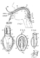
- Figs. 1 to 9 the invention is shown in application to an airway system comprising a laryngeal-mask unit 10 and its airway tube 11, installed through the mouth 12 of a patient.
- the mask unit 10 may be generally as described in any of the above-identified U.S. patents and therefore need not now be described in detail. It suffices to say that mask unit 10 comprises a body portion 13 having a lumen 14 through which the airway tube 11 can establish a free externally accessible ventilation passage, via the patient's mouth 12 and throat 15, and past the epiglottis 16 to the larynx 17.
- the body 13 of mask 10 may be of an elastomer such as silicone rubber and relatively stiff; and body 13 is surrounded by an inflatable ring 18 which is generally elliptical and which is circumferentially united to body 13 in essentially a single plane.
- the inflatable ring 18 may also be of silicone rubber, although preferably relatively soft and flexible compared to body 13.
- An externally accessible tube 19 is the means of supplying air to the inflatable ring 18 and of extracting air from (and therefore collapsing) ring 18 for purposes of insertion in or removal from the patient; check-valve means 21 in tube 19 will be understood to hold a given inflation or to hold a given deflation of ring 18.
- the projecting but blunted distal end 27 of ring 18 is shaped to conform with the base of the hypopharynx where it has established limited entry into the upper sphinctral region of the oesophagus 24.
- the back side of body 13 is covered by a thin flexible panel 25 (Fig. 2) which is peripherally bonded to the inflatable ring 18 (Fig. 1) to define an inflatable back cushion which assures referencing to the back wall of the pharynx and thus is able to load the mask unit forward for enhanced effectiveness of inflated-ring sealing engagement to the laryngeal inlet.
- the inflated ring thus-engaged to the laryngeal inlet, orients the distal-end of the airway tube 11 at an acute angle to the general plane of ring 18 and in substantial alignment with the axis of the laryngeal inlet, for direct airway communication only with the larynx 17.
- the laryngeal-mask unit 10 is of the GLM variety in which an evacuation tube 23 (Fig. 2) serves for extraction and external removal of gastric-discharge products from the oesophagus.
- Tube 23 follows the general course of the airway tube 11, with sealed entry alongside airway tube 11, beneath the back-cushion panel 25, and with passage through the interior of ring 18, near the distal end of the mask; in Fig. 3, the distally open end of the evacuation tube 23 is defined by a re-entrant tubular formation 26 integrally formed with the relatively soft material of ring 18.
- inflation-air supply to the back cushion may be the same (19) as for ring 18, or separate inflating means (not shown) may be provided for these separate inflatable means.
- the relatively softly compliant flexible components may be integrally formed in a single moulding operation, in which the moulded intermediate product is an inside-out version of what will become the finished more flexible part of the finished mask unit 10.
- the moulded intermediate product may thus have the appearance shown in Fig. 5, following the technique described in U.S. Patent 5,305,743, to which reference is made for detailed description. It suffices here to identify the inflation-air inlet formation 28, directed inwardly on a central axis 29 which also includes the outwardly directed distal-end formation of the evacuation tube 26; the central axis 29 may also be understood as identifying the equator plane (perpendicular to the drawing of Fig.
- the mask body 13 (Figs. 4 and 7) is a separately moulded component of relatively stiff nature as compared to the moulded intermediate product of Fig. 5. Stiffness vs . softness will be understood to be relative terms and not necessarily to imply that these components are formed from different materials.
- the body component 13 comprises essentially a moulded dome or bowl 34 having a concave inner surface which conforms to the convex moulded contour of the dome shape 35 of the relatively soft (i.e ., thin-walled) component of Fig. 5, these components being shown in Fig. 6 in assembled relation.
- Relative stiffness (thickness) in the bowl or dome 34 of Fig. 4 is generally in the range 2 to 5 mm, with gradually reducing thickness for greater flexibility in approach to the lower or distal end.
- the bowl or dome 34 has a peripheral edge which terminates in a single plane, for adhesively bonded seating to the ledge 33 of the relatively soft component of Fig. 5, after making the inside-out inversion.
- body 13 is greatest in the region of proximal-end seating to ledge 33, above which an inlet-air formation 36 is oriented on an axis 37 which is not only inclined at an acute angle ⁇ to the plane of seating to ledge 33, but is also laterally offset from the central longitudinal plane of symmetry of the mask, denoted 5-5 in Fig. 3.
- Relative stiffness of body 13 is also enhanced (i) by the fact that its distal half features a slot 38 of width less than the diameter of the re-entrant distal-end tube 26, (ii) by the fact that the re-entrant tube 26 is adhesively retained in cradled support by and between confronting edges of slot 38, and (iii) by the fact that the distal end of evacuation tube 23 is preferably preformed (as seen in Fig. 2) with a quarter-turn helical advance to track the course of slot 38 in the upper or proximal half of body 13.
- the evacuation tube 23 is preferably relatively stiff, e.g ., stiffness (thickness) in the order of magnitude of the material at the upper (proximal) half of body 13, and is seen in Fig. 2 to have telescoping fit to the proximally directed upper end of re-entrant tube 26; this is an adhesively sealed fit.
- the back-cushion panel 25 covers a substantial part of the posterior surface of the mask, being peripherally sealed around the generally elliptical course of inflatable ring 18, and also being centrally adhered to the re-entrant tube 26 for substantially the entire length of tube 26, as suggested by cross-hatching 39.
- the re-entrant tube 26 is adhesively sealed to the adjacent edges of tube-26 local passage through ring 18 at the distal location designated 40 in Fig. 3; for purposes of avoiding undue complexity in the drawings, this adhesively sealed region is not shown but will be understood to be along the line of tube-26 intercept with locally adjacent walls of inflatable ring 18. In Fig. 5, this intercept line is accounted for by a local cut-out 40' at the distal end of the skirt of the intermediate product of Fig. 5.
- FIG. 8 The simplified sectional diagram of Fig. 8 illustrates the functional cooperation of described component parts and features of the described gastro-laryngeal mask construction, in inflated condition, to account for diametrically opposite section cuts through right and left halves of the inflatable ring 18, spaced by body-13 sealed fit to the inner profile of ring 10.
- the back-cushion panel 25, being centrally adhered at 39 to the upper central region of re-entrant tube 26, provides a lifting force which is in the direction to hold open the evacuation tube and, therefore, not to collapse tube 26 when the back cushion is inflated; without this force, in opposition to a retaining force attributable to adhesive connection to body 13 (along edges of slot 38), there would be no tendency to hold a softly compliant tube 26 against collapse, in that the cushion panel would outwardly expand itself to a bowed shape 25' suggested by phantom outline in Fig. 2.
- the effective arcuate extent of_adhesive connection 39 is in the range 45° to 90° about the central axis of tube 26, as seen in Fig. 8.
- the adhesive connection of tube 26 along the straight edges of the distal half of slot 38 accounts for a corresponding range of support of tube 26 against collapse in the circumstance of back-cushion inflation.
- inflation of the ring 18 and back cushion 25 will assure developed vertical forces to hold the evacuation passage of re-entrant tube 26 in substantially open condition, but the transversely opposed arcuate regions (each of approximately 90° arcuate extent) between these adhesively connected regions are vulnerable to compressionally inward bowing, thus reducing the sectional area of tube 26 while the mask is inflated.
- the invention resolves this vulnerability by providing axially spaced stiffening ribs or ridges 42 as integral formations of the re-entrant tube 26, in the initially moulded intermediate product of Fig. 5. As shown, there are three mutually opposed pairs of ridges 42, at axial spacings which are in the order of the unstressed bore diameter of tube 26. For the indicated silicone-rubber material of the product of Fig. 5, the incremental local thickness at ridges 42 is suitably twice or three times the otherwise uniformly thin moulded product of Fig. 5, as seen in Fig. 5A.
- a section taken near the location of tube 26 connection to the more stiffly compliant evacuation tube 23 the inflated condition of the GLM mask of the invention is seen to have an overall "height" dimension H 1 , meaning front-to-back (i.e ., laryngeal inlet-to-pharynx back wall).
- H 1 front-to-back
- this dimension H 1 is seen to be reduced by approximately 50 percent, as shown at H 2 in Fig. 9 for the deflated condition of the same mask.
- the GLM device described thus far has an airway tube 11 that is of larger diameter than the evacuation tube 23; in this circumstance, the airway tube 11 is large enough to accommodate guided insertion of an endotracheal tube.
- the tubes 11, 23 enter the described laryngeal mask 10 in side-by-side relation and are preferably adhesively secured to each other in this side-by-side relation, and along their full longitudinal extent, in order to provide a measure of torsional resistance against twisting, thereby aiding a medically qualified person in quickly and correctly installing a fully deflated GLM in a patient, with assurance that, upon inflation of ring 18 and the back-cushion panel 25, an exclusive and sealed airway connection will be established to the laryngeal inlet, via lumen 14 and from the airway tube 11; concurrently, a similarly exclusive evacuation connection is established to the upper sphinctral region of the oesophagus, via the distal-end opening 43 of tube 26, through the evacuation tube 23, and to suitable waste-collection means (not shown
- the opening 43 When correctly shaped and in its deflated condition, and at the distal end of the GLM, the opening 43 will have been flattened, and this distal end merges with the peripheral lip 18' of the collapsed ring 18. Noting that the entire distal half of the mask is of relatively soft material, stiffened only by indicated adhesive connection, the distal end projects distally and at its upwardly flared merge with lip 18', for low acute-angle incidence to the posterior arcuate profile of the patient's throat passage.
- a medical technician need only make sure that upon inserting the mask via the patient's mouth and throat, the flattened distal end rides the outer (posterior) arcuate contour of the patient's airway, in that the softly flexible nature of the distally projecting and somewhat flattened distal end will be flexibly self-adapting to local irregularities (if any) in the course of passage into the pharynx; final insertional location is noted by an increase in encountered resistance, upon distal-end engagement of the GLM with the upper sphinctral region of the oesophagus.
- inflation air supplied via line 19 and retained by check-valve means 21 establishes (i) the described seal of ring 18 to the laryngeal inlet, (ii) back cushion (panel 25) contact with the back wall of the pharynx, and (iii) full opening of the evacuation tube 26 for maximum accommodation of a possible gastric discharge from the oesophagus.
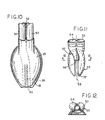
- Fig. 10 illustrates at phantom outline 26' that the flexible length of the re-entrant tube 26 may be of even greater length than the approximately half-mask length shown by the solid lines of Fig. 5.
- arcuate stiffener ridges as described at 42 will be preferred, as long as lateral support is needed to prevent side-wall collapse of the extended tube 26', in the inflated condition of the mask, i.e. , including inflation of back-cushion panel 25.
- Figs. 10 to 12 illustrate another GLM embodiment wherein an airway tube 50 and an evacuation tube 51 are of equal size, adhered (as suggested at 52) to each other in side-by-side relation for torsionally resistant and symmetrically positioned entry into corresponding side-by-side ports 53, 54 of the moulded backing plate 55 of Figs. 11 and 12.
- the backing plate 55 may be similar to plate 13 of Fig. 4, except that in Fig. 11 the somewhat helically arcuate conduit path from the inserted distal end of evacuation tube 51 to the point 56 of softly compliant re-entrant tube (26) connection is provided by an integral passage formation 57 of the backing plate 55.
- the somewhat helically arcuate conduit path from the inserted distal end of evacuation tube 51 to the point 56 of softly compliant re-entrant tube (26) connection is provided by an integral passage formation 57 of the backing plate 55.
- the formation 57 is seen to be in the central vertical plane 58 of symmetry of the bowl of backing plate 55 and in alignment for accepted proximal-end insertional accommodation of a re-entrant tube 26 of thin-walled material to which backing plate 55 is to be assembled, with edges of the straight slot 38' supporting tube 26 in the manner already described.
- an inlet-connection counterbore integrally formed with backing plate 55 for coupled connection of airway tube 50 to the laryngeally exposed side of the mask.
- the drainage tube 26 is integrally-moulded with the non-invertible ring (18), so that an inversion of tube 26 is necessary, to have it project re-entrantly, in the proximal direction, and the moulded product which is to become inflatable ring 18 must be cut away as at 40, to permit inverted tube 26 to "pass through” the inflatable ring, in order to develop a relationship which is suggested by Fig. 5.
- the reinforcement ribs 42 are preferably integrally formed as radially inward rib reinforcements or discontinuities in the moulded bore of tube 26. Inversion of tube 26 places these rib reinforcements on the outer surface of tube 26, so that the bore of tube 26 is inherently smooth.
Abstract
Description
- This invention relates to a laryngeal-mask airway (LMA) device, which is an artificial airway device designed to facilitate lung ventilation in an unconscious patient by forming a low-pressure seal around the laryngeal inlet. An inflatable-ring seal surrounds an appropriately shaped mask which fits into the lower pharynx and is attached to a tube which emerges from the mouth, as for connection to medical gas-supply tubing.
- More particularly, the invention relates to a variety of laryngeal masks, known as gastro-laryngeal masks (GLM), wherein provision is made for airway assurance to the patient who is at risk from vomiting or regurgitation of stomach contents while unconscious. U.S. Patent 5,241,956 deals with this problem by providing an evacuation tube which is open through the center of the inflatable seal of the laryngeal mask, thus utilizing the distal end of the inflatable ring as an inflatable-cuff formation which establishes peripherally sealed engagement to the upper sphinctral region of the oesophagus and centrally supports the distal end of the evacuation tube. In addition, said U.S. Patent 5,241,956 discloses a further inflatable cuff carried by the laryngeal mask and by the evacuation tube, for referencing inflation against the back wall of the pharynx, thus making it possible to establish the laryngeal-inlet seal with reduced inflation pressure, as compared with prior structures not having such an additional inflatable cuff.
- U.S. Patent 5,305,743 discloses moulding techniques for manufacture of a variety of laryngeal masks, including a gastro-laryngeal mask, wherein an inflatable back cushion provides such referencing inflation against the back wall of the pharynx as to widely distribute the back-wall reference, over substantially the full area of the laryngeal mask. Such a back-cushion construction has been found to be mechanically simple and highly effective, and U.S. Patent 5,355,879 discloses such a back cushion for each of several representative laryngeal-mask constructions.
- In practice, although a gastro-laryngeal-mask as described in said Patent 5,355,879 works well, it has the disadvantage that the gastric evacuation channel needs to be sufficiently stiff to prevent its collapse under the influence of the increased pressure within the back-cushion cuff, when it is inflated in the pharynx. A suitably stiff tube is readily provided, but the whole device is then more difficult to insert into the patient's throat, since insertion involves flexing the device around the angle at the back of the tongue. Provision of a pre-curved airway tube facilitates passage around the back of the tongue, but the advancing distal tip end of the device is then more likely to collide with the glottis (or entrance to the larynx), and indeed it may block the larynx by so doing, with consequent danger to the patient.
- The present invention seeks to provide a laryngeal mask construction that specifically avoids the problems and difficulties encountered with the devices of the above U.S. patents and especially of U.S. Patent 5,355,879 by allowing for ready compression and flexure of a gastric passage within a back-cushioned or cuffed gastro-laryngeal mask when the mask is in deflated condition for insertion into the patient's throat.
- Such a construction has been found to enable formation of a flattened flexible leading distal-end edge to self-adapt to and resiliently ride the outer limit of curvature of the patient's airway, throughout the insertional course of the deflated mask and into its locating engagement with the hypopharynx, and to provide for assurance of full patency of the gastric passage within the mask, when the mask has been inflated.
- These objectives are realized by utilizing two structural mechanisms, both of which are operative when the device is inflated; one of these mechanisms prevents lateral compression of the wall of the gastric tube, while the other prevents antero-posterior compression of the wall of the gastric tube. The result is to assure a substantially circular section within relatively soft portions of the evacuation passage as long as the device is inflated and in installed position.
- According to the invention, there is now provided a laryngeal mask airway device comprising
a generally elliptical inflatable ring of relatively thin and softly pliant molded elastomeric material, having an outer periphery adapted for sealed engagement to the laryngeal inlet and including within its inner periphery an apertured panel separating its pharyngeal and laryngeal sides, the ring extending longitudinally between proximal and distal ends and having an inflation port connection at its proximal end, the ring further including at its distal end an open tubular conduit for operative engagement and communication with the oesophageal inlet, the tubular conduit extending from its distally open end proximally on the pharyngeal side of the panel;
a domed backing-plate of relatively stiff material having a concave side terminating in a generally elliptical footing in a geometric plane and sealed around the aperture in the panel at the inner periphery of the elliptical ring and having a proximal airway-tube connector at an acute angle with the panel, the backing plate providing stability to the inner periphery of the elliptical ring and directional stability for the tubular conduit;
an airway tube connected to the connector,
a gastric-discharge tube connected to the tubular conduit; and
an inflatable back cushion comprising a panel of softly compliant material bonded peripherally to the pharyngeal side of the ring and extending over the tubular conduit;
characterized in that
the posterior aspect of the tubular conduit is bonded along its length to the back cushion panel;
the anterior aspect of the tubular conduit is bonded along its length to the backing plate; and
lateral aspects of the tubular conduit are reinforced with circumferentially arcuate ribs. - In a preferred embodiment of the invention, an artificial airway device to facilitate a patient's lung ventilation comprises an airway tube, an evacuation tube, and a laryngeal mask at one end of both tubes. The mask is of generally elliptical configuration and comprises a body or backplate of relatively stiffly compliant nature, and an inflatable annular cuff or ring of relatively softly compliant nature is connected to and surrounds the body or backplate. When inflated, the annular cuff adapts to and seals around the laryngeal inlet, and an inflatable cushion on the exterior of the inflated annulus bears against the back wall of the pharynx, to thereby forwardly load the inflated annulus into sealed relation with the laryngeal inlet, with the backplate dividing the mask between a laryngeal-chamber side and a pharyngeal-chamber side. The relatively stiff backplate is formed for connection to the airway tube for exclusive communication to the larynx through an opening in the backplate; and the backplate is also, configured to guide and support a relatively soft flexible evacuation tube within the pharyngeal-chamber side, from a distally open end for reception of gastric products, to a proximal end for connection to an externally discharging evacuation tube.
- It is a feature of the invention that along an aligning path for the flexible evacuation tube within the pharyngeal-chamber side of the mask, a first significant angular fraction of the periphery of the flexible tube is bonded to a stabilizing portion of the backplate, and that a second angular fraction of the periphery of the flexible tube is continuously bonded to the inner surface of the flexible back cushion, such that generally opposite unbonded further angular regions exist between the bonded regions. These unbonded further regions are provided with external stiffening ribs at a succession of axial intervals, to reinforce the unbonded regions against lateral compression when the back cushion and the inflatable ring are under inflation pressure. In this way, inflation of the annular laryngeal-inlet sealing ring and of the flexible back cushion will assure a maximally open evacuation passage within the mask in inflated condition, essentially without antero-posterior or lateral compression of the passage. And it is further assured that upon deflation of the mask, evacuation-passage compression will be essentially in the sense of achieving a squeezing and somewhat flattening deformation of the discharge passage against the formed back-plate area of evacuation-passage support; such flattening is maximal at the oesophageal end of the discharge passage, so that, when correctly deflated, the device forms a wedge shape for correct insertion.
- The invention will be illustratively described in detail for a presently preferred embodiment, and for certain other embodiments, all in conjunction with the accompanying drawings, in which:
- Fig. 1 is a simplified view, generally in side elevation, for the presently preferred embodiment of an artificial airway device, having at its distal end a laryngeal mask with a gastric-drainage feature of the invention, the same being shown in position for use in a patient;
- Fig. 2 is a fragmentary plan view, to an enlarged scale showing the back or pharynx-facing side of the mask of Fig. 1;
- Fig. 3 is a plan view to the scale of Fig. 2, showing a softly compliant moulded inflatable component of the mask, as seen from the aspect of Fig. 2;
- Fig. 4 is a plan view to the scale of Fig. 2, showing a relatively stiffly compliant rigidising or reinforcing back-plate component of the mask, as seen from the aspect of Fig. 2;
- Fig. 5 is a longitudinal section of the softly compliant component of Fig. 3, to the scale of Figs. 2 to 4 and taken generally in the vertical plane 5-5 of substantial symmetry, but prior to an inside-out deformation step, to create the appearance of Fig. 3;
- Fig. 6 is another view in longitudinal section, to the scale of Figs. 2 to 5 and in the vertical plane 5-5 of Fig. 3, showing the relatively stiff component of Fig. 4 in assembled relation to the softly compliant component of Fig. 3;
- Fig. 7 is a side perspective view, of the proximal end of the rigidising component of Fig. 4;
- Fig. 8 is a simplified cross-sectional view of the inflated mask of Fig. 2, taken at 8-8 in Fig. 2;
- Fig. 9 is a simplified cross-sectional view of the deflated mask of Fig. 2, taken at 8-8 in Fig. 2;
- Fig. 10 is a view similar to Fig. 2, to show a first modification;
- Fig. 11 is a view similar to Fig. 4, to show the back-plate component in the modification of Fig. 10; and
- Fig. 12 is a sectional view, taken at 12-12 in Fig. 11.
-
- Referring first to the preferred embodiment of Figs. 1 to 9, the invention is shown in application to an airway system comprising a laryngeal-
mask unit 10 and its airway tube 11, installed through themouth 12 of a patient. Themask unit 10 may be generally as described in any of the above-identified U.S. patents and therefore need not now be described in detail. It suffices to say thatmask unit 10 comprises abody portion 13 having alumen 14 through which the airway tube 11 can establish a free externally accessible ventilation passage, via the patient'smouth 12 andthroat 15, and past theepiglottis 16 to thelarynx 17. Thebody 13 ofmask 10 may be of an elastomer such as silicone rubber and relatively stiff; andbody 13 is surrounded by aninflatable ring 18 which is generally elliptical and which is circumferentially united tobody 13 in essentially a single plane. Theinflatable ring 18 may also be of silicone rubber, although preferably relatively soft and flexible compared tobody 13. An externallyaccessible tube 19 is the means of supplying air to theinflatable ring 18 and of extracting air from (and therefore collapsing)ring 18 for purposes of insertion in or removal from the patient; check-valve means 21 intube 19 will be understood to hold a given inflation or to hold a given deflation ofring 18. - In the installed position of Fig. 1, the projecting but blunted
distal end 27 ofring 18 is shaped to conform with the base of the hypopharynx where it has established limited entry into the upper sphinctral region of theoesophagus 24. The back side ofbody 13 is covered by a thin flexible panel 25 (Fig. 2) which is peripherally bonded to the inflatable ring 18 (Fig. 1) to define an inflatable back cushion which assures referencing to the back wall of the pharynx and thus is able to load the mask unit forward for enhanced effectiveness of inflated-ring sealing engagement to the laryngeal inlet. The inflated ring, thus-engaged to the laryngeal inlet, orients the distal-end of the airway tube 11 at an acute angle to the general plane ofring 18 and in substantial alignment with the axis of the laryngeal inlet, for direct airway communication only with thelarynx 17. - The laryngeal-
mask unit 10 is of the GLM variety in which an evacuation tube 23 (Fig. 2) serves for extraction and external removal of gastric-discharge products from the oesophagus. Tube 23 follows the general course of the airway tube 11, with sealed entry alongside airway tube 11, beneath the back-cushion panel 25, and with passage through the interior ofring 18, near the distal end of the mask; in Fig. 3, the distally open end of theevacuation tube 23 is defined by a re-entranttubular formation 26 integrally formed with the relatively soft material ofring 18. As explained in U.S. Patent 5,241,956, inflation-air supply to the back cushion may be the same (19) as forring 18, or separate inflating means (not shown) may be provided for these separate inflatable means. - More specifically, for the particular construction shown, the relatively softly compliant flexible components may be integrally formed in a single moulding operation, in which the moulded intermediate product is an inside-out version of what will become the finished more flexible part of the finished
mask unit 10. The moulded intermediate product may thus have the appearance shown in Fig. 5, following the technique described in U.S. Patent 5,305,743, to which reference is made for detailed description. It suffices here to identify the inflation-air inlet formation 28, directed inwardly on acentral axis 29 which also includes the outwardly directed distal-end formation of theevacuation tube 26; thecentral axis 29 may also be understood as identifying the equator plane (perpendicular to the drawing of Fig. 5) which applies to the inflatableannular ring 18, afterevacuation tube 26 has been swung upward (counterclockwise), in the sense suggested byarrow 30, and generally for 180° of rotation about anaxis 31, which (axis 31) is normal to the plane of the drawing of Fig. 5. This 180°rotation tucks tube 26 into the flanged relativelylarge edge 32 of the open skirt of the moulded intermediate product of Fig. 5 and makes it a simple matter to turn the remainder of the skirt inside-out, thus definingring 18, with theedge flange 32 seated on aledge 33 of the upper dome-shaped feature of the moulded intermediate product. - In the preferred form shown, the mask body 13 (Figs. 4 and 7) is a separately moulded component of relatively stiff nature as compared to the moulded intermediate product of Fig. 5. Stiffness vs. softness will be understood to be relative terms and not necessarily to imply that these components are formed from different materials.
- The
body component 13 comprises essentially a moulded dome orbowl 34 having a concave inner surface which conforms to the convex moulded contour of thedome shape 35 of the relatively soft (i.e., thin-walled) component of Fig. 5, these components being shown in Fig. 6 in assembled relation. Relative stiffness (thickness) in the bowl ordome 34 of Fig. 4 is generally in the range 2 to 5 mm, with gradually reducing thickness for greater flexibility in approach to the lower or distal end. The bowl ordome 34 has a peripheral edge which terminates in a single plane, for adhesively bonded seating to theledge 33 of the relatively soft component of Fig. 5, after making the inside-out inversion. - The stiffness of
body 13 is greatest in the region of proximal-end seating toledge 33, above which an inlet-air formation 36 is oriented on anaxis 37 which is not only inclined at an acute angle α to the plane of seating toledge 33, but is also laterally offset from the central longitudinal plane of symmetry of the mask, denoted 5-5 in Fig. 3. Relative stiffness ofbody 13 is also enhanced (i) by the fact that its distal half features aslot 38 of width less than the diameter of the re-entrant distal-end tube 26, (ii) by the fact that there-entrant tube 26 is adhesively retained in cradled support by and between confronting edges ofslot 38, and (iii) by the fact that the distal end ofevacuation tube 23 is preferably preformed (as seen in Fig. 2) with a quarter-turn helical advance to track the course ofslot 38 in the upper or proximal half ofbody 13. Theevacuation tube 23 is preferably relatively stiff, e.g., stiffness (thickness) in the order of magnitude of the material at the upper (proximal) half ofbody 13, and is seen in Fig. 2 to have telescoping fit to the proximally directed upper end ofre-entrant tube 26; this is an adhesively sealed fit. - As also seen in Fig. 2, the back-
cushion panel 25 covers a substantial part of the posterior surface of the mask, being peripherally sealed around the generally elliptical course ofinflatable ring 18, and also being centrally adhered to there-entrant tube 26 for substantially the entire length oftube 26, as suggested by cross-hatching 39. Finally, to assure integrity of theinflatable ring 18, there-entrant tube 26 is adhesively sealed to the adjacent edges of tube-26 local passage throughring 18 at the distal location designated 40 in Fig. 3; for purposes of avoiding undue complexity in the drawings, this adhesively sealed region is not shown but will be understood to be along the line of tube-26 intercept with locally adjacent walls ofinflatable ring 18. In Fig. 5, this intercept line is accounted for by a local cut-out 40' at the distal end of the skirt of the intermediate product of Fig. 5. - The simplified sectional diagram of Fig. 8 illustrates the functional cooperation of described component parts and features of the described gastro-laryngeal mask construction, in inflated condition, to account for diametrically opposite section cuts through right and left halves of the
inflatable ring 18, spaced by body-13 sealed fit to the inner profile ofring 10. The back-cushion panel 25, being centrally adhered at 39 to the upper central region ofre-entrant tube 26, provides a lifting force which is in the direction to hold open the evacuation tube and, therefore, not to collapsetube 26 when the back cushion is inflated; without this force, in opposition to a retaining force attributable to adhesive connection to body 13 (along edges of slot 38), there would be no tendency to hold a softlycompliant tube 26 against collapse, in that the cushion panel would outwardly expand itself to a bowed shape 25' suggested by phantom outline in Fig. 2. - Preferably, the effective arcuate
extent of_adhesive connection 39 is in the range 45° to 90° about the central axis oftube 26, as seen in Fig. 8. Preferably also, the adhesive connection oftube 26 along the straight edges of the distal half ofslot 38 accounts for a corresponding range of support oftube 26 against collapse in the circumstance of back-cushion inflation. In other words, inflation of thering 18 and backcushion 25 will assure developed vertical forces to hold the evacuation passage ofre-entrant tube 26 in substantially open condition, but the transversely opposed arcuate regions (each of approximately 90° arcuate extent) between these adhesively connected regions are vulnerable to compressionally inward bowing, thus reducing the sectional area oftube 26 while the mask is inflated. The invention resolves this vulnerability by providing axially spaced stiffening ribs orridges 42 as integral formations of there-entrant tube 26, in the initially moulded intermediate product of Fig. 5. As shown, there are three mutually opposed pairs ofridges 42, at axial spacings which are in the order of the unstressed bore diameter oftube 26. For the indicated silicone-rubber material of the product of Fig. 5, the incremental local thickness atridges 42 is suitably twice or three times the otherwise uniformly thin moulded product of Fig. 5, as seen in Fig. 5A. - In Fig. 8, a section taken near the location of
tube 26 connection to the more stifflycompliant evacuation tube 23, the inflated condition of the GLM mask of the invention is seen to have an overall "height" dimension H1, meaning front-to-back (i.e., laryngeal inlet-to-pharynx back wall). When the mask is deflated, this dimension H1 is seen to be reduced by approximately 50 percent, as shown at H2 in Fig. 9 for the deflated condition of the same mask. When deflated, as has been pointed out in U.S. Patent 5,297,547, thering 18 collapses into-flattened double walls (marked 18') which are upwardly dished; and although deflation does little to compresstube 26 other than at the region 39' of adhesion to the back-cushion panel 25, the overall deflated extent H2 is essentially unchanged from the dimension H2 which applies for collapse ofring 18. On the other hand, at the distal end of the mask, the collapse ofring 18 is operative upon the formed distal-end opening 43 oftube 26 to somewhat flatten theopening 43, into a generally shovel-shaped distal lip feature which merges smoothly into the adjacent upwardly dished double-wall shape 18' shown in the longitudinal mid-section of Fig. 9. - It will be appreciated that the GLM device described thus far has an airway tube 11 that is of larger diameter than the
evacuation tube 23; in this circumstance, the airway tube 11 is large enough to accommodate guided insertion of an endotracheal tube. Thetubes 11, 23 enter the describedlaryngeal mask 10 in side-by-side relation and are preferably adhesively secured to each other in this side-by-side relation, and along their full longitudinal extent, in order to provide a measure of torsional resistance against twisting, thereby aiding a medically qualified person in quickly and correctly installing a fully deflated GLM in a patient, with assurance that, upon inflation ofring 18 and the back-cushion panel 25, an exclusive and sealed airway connection will be established to the laryngeal inlet, vialumen 14 and from the airway tube 11; concurrently, a similarly exclusive evacuation connection is established to the upper sphinctral region of the oesophagus, via the distal-end opening 43 oftube 26, through theevacuation tube 23, and to suitable waste-collection means (not shown) external to the patient. - More specifically as to insertion of the fully deflated GLM device in a patient, it will be understood that a range of GLM sizes is available from which to select a sufficiently correct size for the patient. Deflation is accomplished via external means (not shown) and via check-valve means 21 to hold the deflated condition wherein the dome shape of
body 13 rises from within the dished peripheral lip 18' of thecollapsed ring 18. A skilled operator is quickly able to develop the desired appearance of the GLM in its deflated state; but for a uniformly correct deflated shaping, it is recommended to use a forming tool. - When correctly shaped and in its deflated condition, and at the distal end of the GLM, the
opening 43 will have been flattened, and this distal end merges with the peripheral lip 18' of thecollapsed ring 18. Noting that the entire distal half of the mask is of relatively soft material, stiffened only by indicated adhesive connection, the distal end projects distally and at its upwardly flared merge with lip 18', for low acute-angle incidence to the posterior arcuate profile of the patient's throat passage. That being the case, a medical technician need only make sure that upon inserting the mask via the patient's mouth and throat, the flattened distal end rides the outer (posterior) arcuate contour of the patient's airway, in that the softly flexible nature of the distally projecting and somewhat flattened distal end will be flexibly self-adapting to local irregularities (if any) in the course of passage into the pharynx; final insertional location is noted by an increase in encountered resistance, upon distal-end engagement of the GLM with the upper sphinctral region of the oesophagus. At this juncture, inflation air supplied vialine 19 and retained by check-valve means 21 establishes (i) the described seal ofring 18 to the laryngeal inlet, (ii) back cushion (panel 25) contact with the back wall of the pharynx, and (iii) full opening of theevacuation tube 26 for maximum accommodation of a possible gastric discharge from the oesophagus. - Beyond what has been described, Fig. 10 illustrates at phantom outline 26' that the flexible length of the
re-entrant tube 26 may be of even greater length than the approximately half-mask length shown by the solid lines of Fig. 5. In that event, arcuate stiffener ridges as described at 42 will be preferred, as long as lateral support is needed to prevent side-wall collapse of the extended tube 26', in the inflated condition of the mask, i.e., including inflation of back-cushion panel 25. - Figs. 10 to 12 illustrate another GLM embodiment wherein an
airway tube 50 and anevacuation tube 51 are of equal size, adhered (as suggested at 52) to each other in side-by-side relation for torsionally resistant and symmetrically positioned entry into corresponding side-by-side ports backing plate 55 of Figs. 11 and 12. Thebacking plate 55 may be similar toplate 13 of Fig. 4, except that in Fig. 11 the somewhat helically arcuate conduit path from the inserted distal end ofevacuation tube 51 to thepoint 56 of softly compliant re-entrant tube (26) connection is provided by anintegral passage formation 57 of thebacking plate 55. Atpoint 56 in Fig. 11, theformation 57 is seen to be in the centralvertical plane 58 of symmetry of the bowl ofbacking plate 55 and in alignment for accepted proximal-end insertional accommodation of are-entrant tube 26 of thin-walled material to whichbacking plate 55 is to be assembled, with edges of the straight slot 38' supportingtube 26 in the manner already described. Also integrally formed withbacking plate 55 is an inlet-connection counterbore for coupled connection ofairway tube 50 to the laryngeally exposed side of the mask. Features in Fig. 10, such as the back-cushion panel 25, theinflatable ring 18, and the adhesively bondedconnection 39 ofpanel 25 totube 26 are all as previously described. - It will be understood that the inside-out technique described in connection with Figs. 5 and 6 for initially moulding and then inverting the skirt of the moulded product, is but one illustration of a way to create the mask and its inflatable ring. In which case the flexible drainage conduit does not get inverted. That being the case, the
reinforcement ribs 42 are initially formed portions of the outer surface of the moulded product. On the other hand, another technique for forming the mask with its inflatable ring, involves moulding the mask bowl integrally with an elliptically configured product as shown in Fig. 13, wherein completion of inflatable-ring (18) integrity requires only an adhesively bonded completion of the ring peripherally around the inner substantially elliptical profile, where backing-plate (13) connection is also adhesively secured. In that case, thedrainage tube 26 is integrally-moulded with the non-invertible ring (18), so that an inversion oftube 26 is necessary, to have it project re-entrantly, in the proximal direction, and the moulded product which is to becomeinflatable ring 18 must be cut away as at 40, to permitinverted tube 26 to "pass through" the inflatable ring, in order to develop a relationship which is suggested by Fig. 5. Of course, iftube 26 is to be inverted, thereinforcement ribs 42 are preferably integrally formed as radially inward rib reinforcements or discontinuities in the moulded bore oftube 26. Inversion oftube 26 places these rib reinforcements on the outer surface oftube 26, so that the bore oftube 26 is inherently smooth.
Claims (10)
- A laryngeal mask airway device comprising:characterized in thata generally elliptical inflatable ring (18) of relatively thin and softly pliant molded elastomeric material, having an outer periphery adapted for sealed engagement to the laryngeal inlet and including within its inner periphery an apertured panel (33) separating its pharyngeal and laryngeal sides, the ring extending longitudinally between proximal and distal ends and having an inflation port connection (28) at its proximal end, the ring further including at its distal end an open tubular conduit (26) for operative engagement and communication with the oesophageal inlet, the tubular conduit extending from its distally open end proximally on the pharyngeal side of the panel;a domed backing-plate (34) of relatively stiff material having a concave side terminating in a generally elliptical footing in a geometric plane and sealed around the aperture in the panel (33) at the inner periphery of the elliptical ring and having a proximal airway-tube connector (36) at an acute angle with the panel, the backing plate providing stability to the inner periphery of the elliptical ring and directional stability for the tubular conduit;an airway tube (11) connected to the connector (36);a gastric-discharge tube (23) connected to the tubular conduit (26); andan inflatable back cushion (25) comprising a panel of softly compliant material bonded peripherally to the pharyngeal side of the ring (18) and extending over the tubular conduit (26);
the posterior aspect of the tubular conduit is bonded along its length to the back cushion panel;
the anterior aspect of the tubular conduit is bonded (39) along its length to the backing plate; and
lateral aspects of the tubular conduit are reinforced with circumferentially arcuate ribs (42). - A device according to claim 1, wherein the airway tube (11) and the gastric-discharge tube (23) are bonded together side-by-side.
- A device according to claim 1 or claim 2, wherein the tubular conduit (26) extends proximally up to 50 percent of the longitudinal extent of the inflatable ring.
- A device according to claim 1 or claim 2, wherein the tubular conduit (26) extends proximally more than 50 percent of the longitudinal extent of the inflatable ring.
- A device according to any one of claims 1 to 4, wherein the backing-plate (34) guides the tubular conduit (26) in a straight proximal direction for substantially the distal half of the longitudinal extent of the mask.
- A device according to claim 5, wherein the backing-plate member (34) guides the tubular-conduit (26) on a generally helical arc to a proximal location connecting with the gastric-discharge tube (23) alongside the airway tube (11).
- A device according to any one of claims 1 to 6, wherein the back cushion panel is tangentially bonded (39) to the tubular conduit.
- A device according to claim 7, wherein the back cushion bond (39) to the tubular conduit extends for substantially the distal half of the longitudinal extent of the inflatable ring.
- A device according to any one of claims 1 to 8, wherein the arcuate ribs (42) are axially spaced.
- A device according to claim 9, wherein the ribs (42) project radially outwardly of the tubular conduit.
Applications Claiming Priority (5)
| Application Number | Priority Date | Filing Date | Title |
|---|---|---|---|
| GB9520141 | 1995-10-03 | ||
| GBGB9520141.4A GB9520141D0 (en) | 1995-10-03 | 1995-10-03 | A gastro-laryngeal mask |
| US60952196A | 1996-03-01 | 1996-03-01 | |
| US609521 | 1996-03-01 | ||
| PCT/GB1996/002425 WO1997012640A1 (en) | 1995-10-03 | 1996-10-03 | Artificial airway device |
Publications (2)
| Publication Number | Publication Date |
|---|---|
| EP0794807A1 EP0794807A1 (en) | 1997-09-17 |
| EP0794807B1 true EP0794807B1 (en) | 2003-05-07 |
Family
ID=26307862
Family Applications (1)
| Application Number | Title | Priority Date | Filing Date |
|---|---|---|---|
| EP96932711A Expired - Lifetime EP0794807B1 (en) | 1995-10-03 | 1996-10-03 | Artificial airway device |
Country Status (12)
| Country | Link |
|---|---|
| EP (1) | EP0794807B1 (en) |
| JP (1) | JP3793927B2 (en) |
| CN (1) | CN1134274C (en) |
| AR (1) | AR003786A1 (en) |
| AU (1) | AU785497B2 (en) |
| BR (1) | BR9606675A (en) |
| CA (1) | CA2206438C (en) |
| DE (1) | DE69627981T2 (en) |
| ES (1) | ES2202473T3 (en) |
| MY (1) | MY138519A (en) |
| TR (1) | TR199700456T1 (en) |
| WO (1) | WO1997012640A1 (en) |
Cited By (9)
| Publication number | Priority date | Publication date | Assignee | Title |
|---|---|---|---|---|
| USD665254S1 (en) | 2011-06-08 | 2012-08-14 | Intersurgical Ag | Airway device packaging |
| US8485188B2 (en) | 2003-08-14 | 2013-07-16 | Muhammed Aslam Nasir | Airway device |
| USD688787S1 (en) | 2011-06-08 | 2013-08-27 | Intersurgical Ag | Airway device cap and strap holder |
| US8778248B2 (en) | 2002-08-14 | 2014-07-15 | Muhammed Aslam Nasir | Method of manufacturing an airway device |
| USD712244S1 (en) | 2011-09-23 | 2014-09-02 | Intersurgical Ag | Medical device package |
| US9265905B2 (en) | 2010-06-24 | 2016-02-23 | Ashkal Developments Limited | Stopper device |
| USD761952S1 (en) | 2012-07-27 | 2016-07-19 | Docsinnovent Limited | Airway device |
| US9592358B2 (en) | 2008-06-04 | 2017-03-14 | Intersurgical Ag | Respiratory interface devices |
| USD1025348S1 (en) | 2020-04-16 | 2024-04-30 | Intersurgical Ag | Airway device |
Families Citing this family (47)
| Publication number | Priority date | Publication date | Assignee | Title |
|---|---|---|---|---|
| GB9606012D0 (en) * | 1996-03-22 | 1996-05-22 | Brain Archibald Ian Jeremy | Laryngeal mask with gastric-drainage feature |
| GB2317830B (en) * | 1996-10-03 | 2000-03-29 | Smiths Industries Plc | Laryngeal mask airways and their manufacture |
| GB9620609D0 (en) * | 1996-10-03 | 1996-11-20 | Smiths Industries Plc | Laryngeal mask airways and their manufacture |
| US6427686B2 (en) | 1996-10-16 | 2002-08-06 | Augustine Medical, Inc. | Airway device with provision for coupling to an introducer |
| US6070581A (en) * | 1996-10-16 | 2000-06-06 | Augustine Medical, Inc. | Laryngeal airway device |
| US6830049B2 (en) | 1996-10-16 | 2004-12-14 | Arizant Healthcare Inc. | Airway device with provision for coupling to an introducer |
| US5937859A (en) * | 1996-10-16 | 1999-08-17 | Augustine Medical, Inc. | Laryngeal airway device |
| GB2318735B (en) * | 1996-11-02 | 2000-04-19 | Smiths Industries Plc | Laryngeal mask airways and their manufacture |
| GB2319478B (en) * | 1996-11-19 | 2000-04-19 | Smiths Industries Plc | Laryngeal mask airways and their manufacture |
| GB9624029D0 (en) * | 1996-11-19 | 1997-01-08 | Smiths Industries Ltd | Laryngeal mask airways and their manufacture |
| US6079409A (en) | 1997-07-25 | 2000-06-27 | Brain; Archibald Ian Jeremy | Intubating laryngeal mask |
| US6110143A (en) * | 1998-06-25 | 2000-08-29 | Kamen; Jack M. | Inflation/deflation medical device |
| GB9817537D0 (en) | 1998-08-13 | 1998-10-07 | Brain Archibald Ian Jeremy | A laryngear mask airway with mutually independant laterally-placed ultra-flexible eastric access/discharge and airway tubes |
| GB9821771D0 (en) | 1998-10-06 | 1998-12-02 | Brain Archibald Ian Jeremy | Improvements relating to laryngeal mask airway devices |
| AU2008230028B2 (en) * | 1998-10-06 | 2012-01-12 | The Laryngeal Mask Company Limited | Laryngeal mask airway device |
| US6119695A (en) * | 1998-11-25 | 2000-09-19 | Augustine Medical, Inc. | Airway device with provision for lateral alignment, depth positioning, and retention in an airway |
| US6705318B1 (en) | 1999-04-09 | 2004-03-16 | Archibald I. J. Brain | Disposable LMA |
| CA2813505C (en) † | 1999-04-09 | 2015-06-23 | The Laryngeal Mask Company Limited | Disposable laryngeal mask airway device |
| US6631720B1 (en) * | 1999-10-07 | 2003-10-14 | Archibald I. J. Brain | Laryngeal mask with large-bore gastric drainage |
| US7159589B2 (en) * | 2001-08-23 | 2007-01-09 | Indian Ocean Medical Inc. | Disposable laryngeal mask airway device |
| US6792948B2 (en) | 2003-01-22 | 2004-09-21 | Archibald I. J. Brain | Laryngeal mask airway device with airway tube having flattened outer circumference and elliptical inner airway passage |
| US7134431B2 (en) | 2003-09-08 | 2006-11-14 | Indian Ocean Medical Inc. | Laryngeal mask airway device with position controlling tab |
| GB0510951D0 (en) | 2005-05-27 | 2005-07-06 | Laryngeal Mask Company The Ltd | Laryngeal mask airway device |
| CN101057994B (en) * | 2006-06-26 | 2011-09-14 | 株式会社佐多商会 | Laryngeal mask with guiding tube used for inserting stomach tube |
| GB2444779A (en) | 2006-12-14 | 2008-06-18 | Archibald Ian Jeremy Brain | A laryngeal mask with with drug delivery means |
| GB0903654D0 (en) * | 2009-03-03 | 2009-04-15 | Laryngeal Mask Company The Ltd | Artificial airway device |
| AU2010269117B2 (en) | 2009-07-06 | 2014-07-10 | Teleflex Life Sciences Llc | Artificial airway |
| AU2010282221B2 (en) | 2009-08-13 | 2015-02-05 | Teleflex Life Sciences Llc | Pressure indicator |
| GB201014773D0 (en) * | 2010-09-06 | 2010-10-20 | Laryngeal Mask Company The Ltd | Laryngeal mask airway device |
| GB201016562D0 (en) | 2010-10-01 | 2010-11-17 | Laryngeal Mask Company The Ltd | Artificial airway device |
| JP5922135B2 (en) | 2010-10-15 | 2016-05-24 | ザ ラリンジアル マスク カンパニー リミテッド | Artificial airway device |
| ES2694800T3 (en) | 2010-11-12 | 2018-12-27 | Wolfe Tory Medical, Inc. | Sprayer for nasal therapy |
| DK201001052A (en) * | 2010-11-19 | 2011-11-10 | Ambu As | A tracheal intubation guide |
| JP6242687B2 (en) | 2011-02-02 | 2017-12-06 | ウメダス、リミテッドUmedaes Limited | Improved artificial airway |
| FR2971945B1 (en) | 2011-02-25 | 2014-05-09 | Pascal Lucchina | BUCCO-PHARYNGAL ROUTER |
| GB201120628D0 (en) | 2011-11-30 | 2012-01-11 | Laryngeal Mask Company The Ltd | Endoscopy device |
| GB201201438D0 (en) | 2012-01-27 | 2012-03-14 | Docsinnovent Ltd | Improved stopper device |
| US10149955B2 (en) | 2013-06-20 | 2018-12-11 | Ambu A/S | Laryngeal mask |
| EP3010571B1 (en) * | 2013-06-20 | 2016-10-05 | Ambu A/S | A laryngeal mask |
| GB201314631D0 (en) | 2013-08-15 | 2013-10-02 | Teleflex Life Sciences | Endoscopy device |
| GB201317596D0 (en) * | 2013-10-04 | 2013-11-20 | Teleflex Life Sciences | Biteblock |
| GB2522403B (en) * | 2013-12-17 | 2017-09-13 | Aslam Nasir Muhammed | Airway device with flexible divider |
| GB2555360B (en) | 2013-12-17 | 2018-10-10 | Intersurgical Ag | Intubating Airway Device |
| USD842456S1 (en) | 2015-12-15 | 2019-03-05 | Intersurgical Ag | Airway device |
| AU201714823S (en) | 2017-02-27 | 2017-10-12 | Teleflex Life Sciences Unlimited Co | Laryngeal mask airway device |
| GB201720733D0 (en) | 2017-12-13 | 2018-01-24 | Ashkal Development Ltd | Airway device |
| CN116747401A (en) * | 2023-06-26 | 2023-09-15 | 中国人民解放军总医院第一医学中心 | Novel high-flow humidifying therapeutic instrument joint |
Family Cites Families (5)
| Publication number | Priority date | Publication date | Assignee | Title |
|---|---|---|---|---|
| GB1399093A (en) * | 1971-06-11 | 1975-06-25 | Matburn Holdings Ltd | Nasal tracheal tubes |
| DK625174A (en) * | 1974-12-02 | 1976-06-03 | V N F Lomholt | RESPIRATORY CATHETER |
| GB9204754D0 (en) * | 1992-03-05 | 1992-04-15 | Brain Archibald Ian Jeremy | Mould for manufacture of a laryngeal mask |
| US5241956A (en) * | 1992-05-21 | 1993-09-07 | Brain Archibald Ian Jeremy | Laryngeal mask airway with concentric drainage of oesophagus discharge |
| US5355879A (en) * | 1992-09-28 | 1994-10-18 | Brain Archibald Ian Jeremy | Laryngeal-mask construction |
-
1996
- 1996-09-28 MY MYPI96004028A patent/MY138519A/en unknown
- 1996-10-03 DE DE69627981T patent/DE69627981T2/en not_active Expired - Lifetime
- 1996-10-03 ES ES96932711T patent/ES2202473T3/en not_active Expired - Lifetime
- 1996-10-03 AU AU71390/96A patent/AU785497B2/en not_active Expired
- 1996-10-03 EP EP96932711A patent/EP0794807B1/en not_active Expired - Lifetime
- 1996-10-03 AR ARP960104593A patent/AR003786A1/en unknown
- 1996-10-03 TR TR97/00456T patent/TR199700456T1/en unknown
- 1996-10-03 JP JP51407397A patent/JP3793927B2/en not_active Expired - Lifetime
- 1996-10-03 CN CNB961911670A patent/CN1134274C/en not_active Expired - Lifetime
- 1996-10-03 CA CA002206438A patent/CA2206438C/en not_active Expired - Lifetime
- 1996-10-03 BR BR9606675A patent/BR9606675A/en not_active IP Right Cessation
- 1996-10-03 WO PCT/GB1996/002425 patent/WO1997012640A1/en active IP Right Grant
Cited By (13)
| Publication number | Priority date | Publication date | Assignee | Title |
|---|---|---|---|---|
| US9266268B2 (en) | 2002-08-14 | 2016-02-23 | Muhammed Aslam Nasir | Method of manufacturing an airway device |
| US8778248B2 (en) | 2002-08-14 | 2014-07-15 | Muhammed Aslam Nasir | Method of manufacturing an airway device |
| US9475223B2 (en) | 2002-08-14 | 2016-10-25 | Muhammed Aslam Nasir | Method of manufacturing an airway device |
| US8485188B2 (en) | 2003-08-14 | 2013-07-16 | Muhammed Aslam Nasir | Airway device |
| US9592358B2 (en) | 2008-06-04 | 2017-03-14 | Intersurgical Ag | Respiratory interface devices |
| US9265905B2 (en) | 2010-06-24 | 2016-02-23 | Ashkal Developments Limited | Stopper device |
| USD688787S1 (en) | 2011-06-08 | 2013-08-27 | Intersurgical Ag | Airway device cap and strap holder |
| USD665254S1 (en) | 2011-06-08 | 2012-08-14 | Intersurgical Ag | Airway device packaging |
| USD712244S1 (en) | 2011-09-23 | 2014-09-02 | Intersurgical Ag | Medical device package |
| USD768846S1 (en) | 2012-01-27 | 2016-10-11 | Ashkal Developments Limited | Airway device |
| USD769442S1 (en) | 2012-01-27 | 2016-10-18 | Ashkal Developments Limited | Airway device |
| USD761952S1 (en) | 2012-07-27 | 2016-07-19 | Docsinnovent Limited | Airway device |
| USD1025348S1 (en) | 2020-04-16 | 2024-04-30 | Intersurgical Ag | Airway device |
Also Published As
| Publication number | Publication date |
|---|---|
| TR199700456T1 (en) | 1997-10-21 |
| DE69627981T2 (en) | 2004-02-19 |
| ES2202473T3 (en) | 2004-04-01 |
| AR003786A1 (en) | 1998-09-09 |
| DE69627981D1 (en) | 2003-06-12 |
| EP0794807A1 (en) | 1997-09-17 |
| AU785497B2 (en) | 2008-07-24 |
| AU7139096A (en) | 1997-04-28 |
| JPH10510462A (en) | 1998-10-13 |
| WO1997012640A1 (en) | 1997-04-10 |
| JP3793927B2 (en) | 2006-07-05 |
| MY138519A (en) | 2009-06-30 |
| CA2206438A1 (en) | 1997-04-10 |
| CN1166138A (en) | 1997-11-26 |
| BR9606675A (en) | 1997-10-21 |
| CA2206438C (en) | 2007-09-18 |
| CN1134274C (en) | 2004-01-14 |
Similar Documents
| Publication | Publication Date | Title |
|---|---|---|
| EP0794807B1 (en) | Artificial airway device | |
| US5878745A (en) | Gastro-laryngeal mask | |
| US5871012A (en) | Laryngeal mask airways and their manufacture | |
| US5355879A (en) | Laryngeal-mask construction | |
| US6012452A (en) | Laryngeal mask assemblies | |
| US6631720B1 (en) | Laryngeal mask with large-bore gastric drainage | |
| US5241956A (en) | Laryngeal mask airway with concentric drainage of oesophagus discharge | |
| AU733952B2 (en) | Laryngeal mask assemblies | |
| US7097802B2 (en) | Disposable LMA | |
| JP5150851B2 (en) | Disposable laryngeal mask device | |
| PL198866B1 (en) | Laryngeal mask airway device | |
| JPH10314308A (en) | Mask assembly for larynx part | |
| CN103189090A (en) | Artificial airway device | |
| GB2317830A (en) | Laryngeal mask assembly | |
| GB2324737A (en) | Laryngeal mask assembly | |
| CA2100998C (en) | Laryngeal mask airway with concentric drainage of oesophagus discharge |
Legal Events
| Date | Code | Title | Description |
|---|---|---|---|
| PUAI | Public reference made under article 153(3) epc to a published international application that has entered the european phase |
Free format text: ORIGINAL CODE: 0009012 |
|
| AK | Designated contracting states |
Kind code of ref document: A1 Designated state(s): DE ES FR GB IT NL |
|
| 17P | Request for examination filed |
Effective date: 19970917 |
|
| 17Q | First examination report despatched |
Effective date: 20000329 |
|
| GRAH | Despatch of communication of intention to grant a patent |
Free format text: ORIGINAL CODE: EPIDOS IGRA |
|
| GRAH | Despatch of communication of intention to grant a patent |
Free format text: ORIGINAL CODE: EPIDOS IGRA |
|
| GRAA | (expected) grant |
Free format text: ORIGINAL CODE: 0009210 |
|
| AK | Designated contracting states |
Designated state(s): DE ES FR GB IT NL |
|
| REG | Reference to a national code |
Ref country code: GB Ref legal event code: FG4D |
|
| REF | Corresponds to: |
Ref document number: 69627981 Country of ref document: DE Date of ref document: 20030612 Kind code of ref document: P |
|
| ET | Fr: translation filed | ||
| PLBE | No opposition filed within time limit |
Free format text: ORIGINAL CODE: 0009261 |
|
| STAA | Information on the status of an ep patent application or granted ep patent |
Free format text: STATUS: NO OPPOSITION FILED WITHIN TIME LIMIT |
|
| REG | Reference to a national code |
Ref country code: ES Ref legal event code: FG2A Ref document number: 2202473 Country of ref document: ES Kind code of ref document: T3 |
|
| 26N | No opposition filed |
Effective date: 20040210 |
|
| NLS | Nl: assignments of ep-patents |
Owner name: INDIAN OCEAN MEDICAL INC. |
|
| REG | Reference to a national code |
Ref country code: FR Ref legal event code: CA |
|
| REG | Reference to a national code |
Ref country code: FR Ref legal event code: TP |
|
| REG | Reference to a national code |
Ref country code: FR Ref legal event code: TP |
|
| REG | Reference to a national code |
Ref country code: GB Ref legal event code: 732E Free format text: REGISTERED BETWEEN 20101111 AND 20101117 |
|
| REG | Reference to a national code |
Ref country code: ES Ref legal event code: PC2A Owner name: THE LARYNGEAL MASK COMPANY LTD. Effective date: 20110419 |
|
| REG | Reference to a national code |
Ref country code: NL Ref legal event code: SD Effective date: 20130104 |
|
| REG | Reference to a national code |
Ref country code: GB Ref legal event code: 732E Free format text: REGISTERED BETWEEN 20131121 AND 20131127 |
|
| REG | Reference to a national code |
Ref country code: FR Ref legal event code: PLFP Year of fee payment: 20 |
|
| PGFP | Annual fee paid to national office [announced via postgrant information from national office to epo] |
Ref country code: GB Payment date: 20150930 Year of fee payment: 20 Ref country code: ES Payment date: 20150915 Year of fee payment: 20 |
|
| PGFP | Annual fee paid to national office [announced via postgrant information from national office to epo] |
Ref country code: FR Payment date: 20150923 Year of fee payment: 20 |
|
| PGFP | Annual fee paid to national office [announced via postgrant information from national office to epo] |
Ref country code: IT Payment date: 20151026 Year of fee payment: 20 Ref country code: DE Payment date: 20150929 Year of fee payment: 20 |
|
| PGFP | Annual fee paid to national office [announced via postgrant information from national office to epo] |
Ref country code: NL Payment date: 20151012 Year of fee payment: 20 |
|
| REG | Reference to a national code |
Ref country code: DE Ref legal event code: R071 Ref document number: 69627981 Country of ref document: DE |
|
| REG | Reference to a national code |
Ref country code: NL Ref legal event code: MK Effective date: 20161002 |
|
| REG | Reference to a national code |
Ref country code: GB Ref legal event code: PE20 Expiry date: 20161002 |
|
| PG25 | Lapsed in a contracting state [announced via postgrant information from national office to epo] |
Ref country code: GB Free format text: LAPSE BECAUSE OF EXPIRATION OF PROTECTION Effective date: 20161002 |
|
| REG | Reference to a national code |
Ref country code: ES Ref legal event code: FD2A Effective date: 20170126 |
|
| PG25 | Lapsed in a contracting state [announced via postgrant information from national office to epo] |
Ref country code: ES Free format text: LAPSE BECAUSE OF EXPIRATION OF PROTECTION Effective date: 20161004 |