EP0794359A2 - Motor structure - Google Patents
Motor structure Download PDFInfo
- Publication number
- EP0794359A2 EP0794359A2 EP97300821A EP97300821A EP0794359A2 EP 0794359 A2 EP0794359 A2 EP 0794359A2 EP 97300821 A EP97300821 A EP 97300821A EP 97300821 A EP97300821 A EP 97300821A EP 0794359 A2 EP0794359 A2 EP 0794359A2
- Authority
- EP
- European Patent Office
- Prior art keywords
- output shaft
- motor structure
- rotor
- nitride layer
- screw part
- Prior art date
- Legal status (The legal status is an assumption and is not a legal conclusion. Google has not performed a legal analysis and makes no representation as to the accuracy of the status listed.)
- Granted
Links
Images


Classifications
-
- F—MECHANICAL ENGINEERING; LIGHTING; HEATING; WEAPONS; BLASTING
- F16—ENGINEERING ELEMENTS AND UNITS; GENERAL MEASURES FOR PRODUCING AND MAINTAINING EFFECTIVE FUNCTIONING OF MACHINES OR INSTALLATIONS; THERMAL INSULATION IN GENERAL
- F16H—GEARING
- F16H25/00—Gearings comprising primarily only cams, cam-followers and screw-and-nut mechanisms
- F16H25/18—Gearings comprising primarily only cams, cam-followers and screw-and-nut mechanisms for conveying or interconverting oscillating or reciprocating motions
- F16H25/20—Screw mechanisms
- F16H2025/2062—Arrangements for driving the actuator
- F16H2025/2075—Coaxial drive motors
-
- F—MECHANICAL ENGINEERING; LIGHTING; HEATING; WEAPONS; BLASTING
- F16—ENGINEERING ELEMENTS AND UNITS; GENERAL MEASURES FOR PRODUCING AND MAINTAINING EFFECTIVE FUNCTIONING OF MACHINES OR INSTALLATIONS; THERMAL INSULATION IN GENERAL
- F16H—GEARING
- F16H25/00—Gearings comprising primarily only cams, cam-followers and screw-and-nut mechanisms
- F16H25/18—Gearings comprising primarily only cams, cam-followers and screw-and-nut mechanisms for conveying or interconverting oscillating or reciprocating motions
- F16H25/20—Screw mechanisms
- F16H25/24—Elements essential to such mechanisms, e.g. screws, nuts
- F16H2025/249—Special materials or coatings for screws or nuts
-
- F—MECHANICAL ENGINEERING; LIGHTING; HEATING; WEAPONS; BLASTING
- F16—ENGINEERING ELEMENTS AND UNITS; GENERAL MEASURES FOR PRODUCING AND MAINTAINING EFFECTIVE FUNCTIONING OF MACHINES OR INSTALLATIONS; THERMAL INSULATION IN GENERAL
- F16H—GEARING
- F16H25/00—Gearings comprising primarily only cams, cam-followers and screw-and-nut mechanisms
- F16H25/18—Gearings comprising primarily only cams, cam-followers and screw-and-nut mechanisms for conveying or interconverting oscillating or reciprocating motions
- F16H25/20—Screw mechanisms
- F16H25/22—Screw mechanisms with balls, rollers, or similar members between the co-operating parts; Elements essential to the use of such members
- F16H25/2204—Screw mechanisms with balls, rollers, or similar members between the co-operating parts; Elements essential to the use of such members with balls
Definitions
- This invention relates to a motor structure usable as a driving source to cause a linear movement such as a head actuator of a floppy disc driving device (hereinafter referred to as an FDD), and more particularly, to a motor structure where a pair of sliding parts engage each other to convey a driving force, and further to a motor structure equipped with means for preventing its linearly moving output shaft from rotating.
- a motor structure usable as a driving source to cause a linear movement such as a head actuator of a floppy disc driving device (hereinafter referred to as an FDD)
- FDD floppy disc driving device
- a linear actuator using a two-phase synchronous motor such as an actuator of an FDD
- screw means to convert a moving direction in a linear actuator.
- a screw structure using ball is employed to reduce a frictional loss caused therein and attain high output and high efficiency, as disclosed in Japanese Utility Model Laid-Open No. 62-3080. Therefore, such an actuator structure is expensive because of installing balls, and so it may be applied only in a limited technical field.
- a screw structure without balls is inexpensive, but it is remarkably inferior in conversion efficiency due to a large frictional loss. Additionally, it is remarkably inferior in durability because of a large abrasion loss of resin of the screw, and then it is far from an actual use.
- This invention is presented to overcome the above problems, and it has an object to provide a motor structure having sliding parts which are highly durable even when it is subject to a wide temperature range, and another object to provide a motor structure wherein the above sliding parts are provided as a rotation preventing mechanism for output shaft, and further object to provide a motor structure wherein the above sliding parts are provided as a screw structure to transfer a driving force to an output shaft.
- this invention provides a motor structure having at least two sliding parts engaged with each other through which a driving force is transferred, wherein a surface material of one sliding part is of polyphenylene sulfide (PPS) resin and a surface material of the other sliding part is of a nitride layer.
- PPS polyphenylene sulfide
- this invention provides a motor structure having an output screw shaft with a screw portion engaged with a screw part provided on the center of a rotor rotated by electromagnetic interaction to move the output shaft in its axial direction by the rotation of the rotor, either one of sliding contact parts being formed of PPS resin, the other being formed of metal, on the surface on which a nitride layer is formed.
- the above sliding contact parts compose the screw part between the center portion of the rotor and the output shaft, and another sliding contact parts compose the output shaft and a through-hole part for the output shaft provided on a stator housing.
- the female screw is formed of PPS resin having a high heat resistance and a small linear expansion coefficient so as to minimize the friction resistance between the female screw and the male screw, metal is used for the male screw formed an outer surface of the output shaft.
- the other sliding part on the output shaft is formed in such a way that a longitudinal portion of the output shaft having a D-shaped cross section is cut away to form a plain surface thereon in order to prevent a rotation of the output shaft.
- the surface of the output shaft which is forced to move in longitudinal direction surface is subjected to nitriding, whereby the friction is further reduced, and the durability is also improved.
- a linear actuator highly durable with a simple structure and usable within a wide temperature range can be obtained.
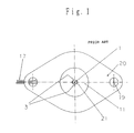
- Fig. 1 shows a plane view showing one embodiment of this invention.
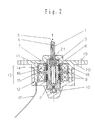
- Fig. 2 is a vertical section view showing one embodiment of this invention.
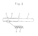
- Fig. 3 is a section view of an output shaft.
- Fig. 4 is a characteristic curve showing a change of a force depending on the presence of a surface treatment in an endurance test of one embodiment of this invention.
- Fig. 5 is a comparative characteristic curve showing the relation between the surface treatment and the wear loss of the output shaft in one embodiment of this invention.
- Fig. 6 is a partial section view showing another embodiment of this invention.
- Fig. 7 is a partial section view showing a further embodiment of this invention.
- Fig. 1 is a plane view showing one embodiment of the invention
- Fig. 2 is a vertical section view of the same.
- denoted at numeral 1 is an output shaft, which has a male screw part 2 made of stainless steel, a pair of rotation preventing D-cut parts 3 (as illustrated later in details) provided in order to prevent the rotation of the output shaft 1, and plain surfaces 4 formed on the D-cut parts 3.
- a nitride layer 5 is formed on the surface of the output shaft 1, particularly, on the surface of the male screw part 2 so as to reduce the frictional resistance and improve the durability.
- the nitride layer 5 is a ceramic thin layer, for example, consisting of a nitride such as silicon nitride, which can be formed on the surface of the output shaft 1 by a known method such as PVD or CVD, and this nitriding can be also performed by a treatment for generating a compound such as iron nitride, that is, a TUFFTRIDE treatment (salt bath method) or sulfunite (PVD method). Otherwise, a polycarboxysilane solution or organic silicon polymer may be applied to the surface of the output shaft 1 subject to metal working, followed by baking in an ammonia atmosphere to form a thin nitride film.
- the nitride layer 5 is about 10 micrometers in thickness.
- the nitride layer 5 may be provided on a whole surface of the output shaft 1, or only on a whole surface part of the male screw part 2.
- a rotor sleeve 6 Denoted at a numeral 6 is a rotor sleeve formed of PPS resin, which has on its bore side a female screw part 7 engaged with the male screw part 2 of the output shaft 1, and a rotor magnet part 8 of permanent magnet fitted and adhered to the outer circumference.
- the rotor sleeve 6 is made of the PPS resin, whereby the heat resistant temperature is increased, compared with polyacetal resin most frequently used as a sliding material in the past, so that the using environment can be set widely.
- the rotor sleeve 6 has bearings 9, 10 on both the ends, and the rotor sleeve 6 is rotatably held by both of the bearing 9 in a stator housing 11 and the bearing 10 in a cover 12.
- a stator assembly 13 is composed of stator yokes 14, 15 and a coil 16.
- this embodiment is related to a two-phase synchronous motor having a stator consisting of a stator yoke formed by three-dimensionally bending a steel plate of a soft magnetic material and a coil formed by winding a wire consisting of a polyurethane resin-covered conductor on a bobbin; and a rotor having a screw type motion conversion mechanism for converting a rotary motion to a linear motion on the inner circumference of a rotor magnet consisting of a field permanent magnet provided so as to be opposite, with a fine space, to the outer circumference of an armature consisting of a permanent magnet opposed to the pole teeth of the stator through a cavity, and having a linearly moving output shaft, and it has the same structure as the stator of a so-called 2 phase claw pole type stepping motor.
- Denoted at 17 is the lead wires of the coils 16.
- the rotor magnet 8 and the stator assembly 13 are concentrically arranged with a fine space, and the stator assembly 13 is housed in the stator housing 11.
- the cover 12 is centered with the stator housing 11 by means of a fitting part 18.
- a flange 20 having a motor mounting holes 19 is integrated to the stator housing 11.
- this through-hole 21 further has a flat part to be fitted to the flat part of the rotation preventing D-cut part 3 of the output shaft 1, the output shaft 1 can not rotate.
- the output shaft 1 is moved, for example, upward as designated by the arrow because of a working of the screw structure in which the male screw part 2 is screwed to the female screw part 7.
- the rotor sleeve 6 is rotated in the opposite direction to the above, the output shaft 1 is moved downward according to the arrow.
- the female screw part 7 is formed of PPS resin
- the male screw part 2 has a structure in which the surface of metal is covered with the nitride layer, and the contact surfaces of the screws thus substantially consist of the PPS resin and the nitride.
- This combination in the contact surface minimizes the abrasion loss of the PPS resin part with the lapse of time. Therefore, the positional precision of the output shaft 1 is held more precisely than in a conventional one even in case of a long-time contact, and the positional precision of a data read and write head provided on a floppy disk which is a memory device for a computer, for example, can be held long.
- Figs. 4 and 5 are characteristic curves for backing up these effects, in which Fig. 4 is a characteristic curve showing a change of a force depending on the presence of the surface treatment in an endurance test, and Fig. 5 is a comparative characteristic curve showing the relation between the surface treatment of the output shaft which is the most important in this invention and the wear loss.
- Fig. 4 is a characteristic curve showing a change of a force depending on the presence of the surface treatment in an endurance test
- Fig. 5 is a comparative characteristic curve showing the relation between the surface treatment of the output shaft which is the most important in this invention and the wear loss.
- the wear of the screw part, particularly, the PPS resin part in the conventional example shown by the dotted line also becomes conspicuous from when about 10 hours passed after use, compared with that in this invention, and the wear loss is increased more beyond comparison with that in this invention when it exceeds 1000 hours. It is found from these drawings that a remarkable difference comes out in the force of the output shaft 1 and the wear loss of the screw with the lapse of time depending on the presence of the surface treatment.
- the output shaft 1 is formed of metal
- the rotor sleeve 6 is formed of PPS resin
- a structure such that the output shaft 1 is formed of PPS resin, the screw on the inner circumference of the rotor sleeve 6 is formed of metal, and the nitride layer is formed on its surface may be employed.
- FIG. 6 is a partial section view showing the state where an output shaft 100 passes through a stator housing 101.
- the output shaft 100 is formed of PPS resin.
- the stator housing 101 is formed of metal such as steel.
- the output shaft 100 passes through a through-hole 102 bored in the stator housing 101, and vertically moved in the arrowed direction by a two-phase synchronous motor in the same manner as the embodiment described above.
- a nitride layer 103 is formed on an inner edge of the through-hole 102 bored in the stator housing 101.
- the nitride layer 103 may be formed by applying a polycarboxysilane solution or organic silicon polymer to the circumferential surface of the through-hole 102, followed by baking in an ammonia atmosphere.
- FIG. 7 is a partial section view showing the state where an output shaft 200 passes through a stator housing 201.
- the output shaft 200 is formed of metal
- the stator housing 201 is also formed of metal.
- the stator housing 201 has a holding hole 202, and a bearing ring 203 formed of PPS resin is fitted to the holding hole 202.
- the center hole of the bearing ring 203 has the same form as the cross sectional form of the output shaft 200.
- a nitride layer 204 is formed on the surface of the output shaft 200.
- the output shaft 200 in this embodiment is vertically moved in the arrowed direction by a two-phase synchronous motor in the same manner as the above embodiment.
- either one of the sliding contact parts is formed of PPS resin, and the other is formed of metal, on the surface of which a nitride layer is formed, in the motor structure having an output shaft with a screw screwed to a screw part provided in the center of a rotor rotated by electromagnetic interaction to move the output shaft in the axial direction by the rotation of the rotor, the wear resistance in the contact part of the motor structure is improved, the frictional resistance of the sliding contact part is never increased over a long time, compared with a conventional one, and many effects of invention such that the positional control of the head, when applied to a floppy disc driving device for a computer, can be precisely executed over a long time are provided.
Abstract
Description
- This invention relates to a motor structure usable as a driving source to cause a linear movement such as a head actuator of a floppy disc driving device (hereinafter referred to as an FDD), and more particularly, to a motor structure where a pair of sliding parts engage each other to convey a driving force, and further to a motor structure equipped with means for preventing its linearly moving output shaft from rotating.
- In a linear actuator using a two-phase synchronous motor such as an actuator of an FDD, it is well known to use screw means to convert a moving direction in a linear actuator. A screw structure using ball is employed to reduce a frictional loss caused therein and attain high output and high efficiency, as disclosed in Japanese Utility Model Laid-Open No. 62-3080. Therefore, such an actuator structure is expensive because of installing balls, and so it may be applied only in a limited technical field. On the other hand, a screw structure without balls is inexpensive, but it is remarkably inferior in conversion efficiency due to a large frictional loss. Additionally, it is remarkably inferior in durability because of a large abrasion loss of resin of the screw, and then it is far from an actual use. Such abrasion occurs markedly, in particular, when a range of working temperature becomes wide. Referring to another problem in this prior art, means for preventing an output shaft from rotating is installed in a device receiving an output from a motor so that the device requires a mounting space therefor. It is not preferable to downsizing of an equipment. Further, since it results in controlling an output shaft movement precisely by using two or more regulating parts, such control is too complicated.
- Although it is generally known that a preferable result such as reduction in abrasion loss can be obtained by using resin for a female screw and metal for a male screw in a motion conversion mechanism with a screw, it can be barely proved, in substance, that the so-called scuffing or seizure of the sliding parts is hardly caused to stabilize the sliding parts by selecting, as the materials for the sliding parts, those differed in hardness so as to minimize the friction as much as possible; and the fact is that each determines after examination to which part the resin is used, or which resin is suitable therefor according to the purpose of use. Since the output shaft is provided with many sliding parts, and is apt to hit itself against a bench or another part at handling. Consequently, the output shaft must be formed of a strong material enough to hold, preferably formed of a metal.
- This invention is presented to overcome the above problems, and it has an object to provide a motor structure having sliding parts which are highly durable even when it is subject to a wide temperature range, and another object to provide a motor structure wherein the above sliding parts are provided as a rotation preventing mechanism for output shaft, and further object to provide a motor structure wherein the above sliding parts are provided as a screw structure to transfer a driving force to an output shaft.
- To solve the problems as described above, this invention provides a motor structure having at least two sliding parts engaged with each other through which a driving force is transferred, wherein a surface material of one sliding part is of polyphenylene sulfide (PPS) resin and a surface material of the other sliding part is of a nitride layer. In addition, this invention provides a motor structure having an output screw shaft with a screw portion engaged with a screw part provided on the center of a rotor rotated by electromagnetic interaction to move the output shaft in its axial direction by the rotation of the rotor, either one of sliding contact parts being formed of PPS resin, the other being formed of metal, on the surface on which a nitride layer is formed. The above sliding contact parts compose the screw part between the center portion of the rotor and the output shaft, and another sliding contact parts compose the output shaft and a through-hole part for the output shaft provided on a stator housing. As a piece of specific examples, the female screw is formed of PPS resin having a high heat resistance and a small linear expansion coefficient so as to minimize the friction resistance between the female screw and the male screw, metal is used for the male screw formed an outer surface of the output shaft. The other sliding part on the output shaft is formed in such a way that a longitudinal portion of the output shaft having a D-shaped cross section is cut away to form a plain surface thereon in order to prevent a rotation of the output shaft. The surface of the output shaft which is forced to move in longitudinal direction surface is subjected to nitriding, whereby the friction is further reduced, and the durability is also improved. Thus, a linear actuator highly durable with a simple structure and usable within a wide temperature range can be obtained.
- In the accompanying drawings:
- Fig. 1 shows a plane view showing one embodiment of this invention.
- Fig. 2 is a vertical section view showing one embodiment of this invention.
- Fig. 3 is a section view of an output shaft.
- Fig. 4 is a characteristic curve showing a change of a force depending on the presence of a surface treatment in an endurance test of one embodiment of this invention.
- Fig. 5 is a comparative characteristic curve showing the relation between the surface treatment and the wear loss of the output shaft in one embodiment of this invention.
- Fig. 6 is a partial section view showing another embodiment of this invention.
- Fig. 7 is a partial section view showing a further embodiment of this invention.
- One embodiment of this invention is illustrated in detail in reference to the accompanying drawings. Fig. 1 is a plane view showing one embodiment of the invention, and Fig. 2 is a vertical section view of the same. In these drawings, denoted at
numeral 1 is an output shaft, which has amale screw part 2 made of stainless steel, a pair of rotation preventing D-cut parts 3 (as illustrated later in details) provided in order to prevent the rotation of theoutput shaft 1, and plain surfaces 4 formed on the D-cut parts 3. As shown in Fig. 3, anitride layer 5 is formed on the surface of theoutput shaft 1, particularly, on the surface of themale screw part 2 so as to reduce the frictional resistance and improve the durability. Thenitride layer 5 is a ceramic thin layer, for example, consisting of a nitride such as silicon nitride, which can be formed on the surface of theoutput shaft 1 by a known method such as PVD or CVD, and this nitriding can be also performed by a treatment for generating a compound such as iron nitride, that is, a TUFFTRIDE treatment (salt bath method) or sulfunite (PVD method). Otherwise, a polycarboxysilane solution or organic silicon polymer may be applied to the surface of theoutput shaft 1 subject to metal working, followed by baking in an ammonia atmosphere to form a thin nitride film. Thenitride layer 5 is about 10 micrometers in thickness. Thenitride layer 5 may be provided on a whole surface of theoutput shaft 1, or only on a whole surface part of themale screw part 2. - Denoted at a numeral 6 is a rotor sleeve formed of PPS resin, which has on its bore side a
female screw part 7 engaged with themale screw part 2 of theoutput shaft 1, and arotor magnet part 8 of permanent magnet fitted and adhered to the outer circumference. The rotor sleeve 6 is made of the PPS resin, whereby the heat resistant temperature is increased, compared with polyacetal resin most frequently used as a sliding material in the past, so that the using environment can be set widely. - The rotor sleeve 6 has
bearings 9, 10 on both the ends, and the rotor sleeve 6 is rotatably held by both of the bearing 9 in astator housing 11 and thebearing 10 in acover 12. Astator assembly 13 is composed ofstator yokes coil 16. More specifically, this embodiment is related to a two-phase synchronous motor having a stator consisting of a stator yoke formed by three-dimensionally bending a steel plate of a soft magnetic material and a coil formed by winding a wire consisting of a polyurethane resin-covered conductor on a bobbin; and a rotor having a screw type motion conversion mechanism for converting a rotary motion to a linear motion on the inner circumference of a rotor magnet consisting of a field permanent magnet provided so as to be opposite, with a fine space, to the outer circumference of an armature consisting of a permanent magnet opposed to the pole teeth of the stator through a cavity, and having a linearly moving output shaft, and it has the same structure as the stator of a so-called 2 phase claw pole type stepping motor. Denoted at 17 is the lead wires of thecoils 16. - The
rotor magnet 8 and thestator assembly 13 are concentrically arranged with a fine space, and thestator assembly 13 is housed in thestator housing 11. Thecover 12 is centered with thestator housing 11 by means of afitting part 18. Aflange 20 having amotor mounting holes 19 is integrated to thestator housing 11. - The operation of this invention is further illustrated. When a prescribed pulse driving voltage is applied to the
lead wires 17 of thecoils 16 in the state shown in Fig. 2, the rotor sleeve 6 starts to rotate, for example, clockwise by the interaction between the magnetic flux generated from thecoils 16 and the magnetic flux generated from therotor magnets 8. Theoutput shaft 1 screwed to the inside of the rotor sleeve 6 also is forced to rotate together with it by the rotation of the rotor sleeve 6. However, the rotation preventing D-cutpart 3 is formed on the upper part of theoutput shaft 1, and this part passes through a through-hole 21 bored in thestator housing 11. Since this through-hole 21 further has a flat part to be fitted to the flat part of the rotation preventing D-cutpart 3 of theoutput shaft 1, theoutput shaft 1 can not rotate. Thus, theoutput shaft 1 is moved, for example, upward as designated by the arrow because of a working of the screw structure in which themale screw part 2 is screwed to thefemale screw part 7. When the rotor sleeve 6 is rotated in the opposite direction to the above, theoutput shaft 1 is moved downward according to the arrow. - As described above for the constitution, the
female screw part 7 is formed of PPS resin, themale screw part 2 has a structure in which the surface of metal is covered with the nitride layer, and the contact surfaces of the screws thus substantially consist of the PPS resin and the nitride. This combination in the contact surface minimizes the abrasion loss of the PPS resin part with the lapse of time. Therefore, the positional precision of theoutput shaft 1 is held more precisely than in a conventional one even in case of a long-time contact, and the positional precision of a data read and write head provided on a floppy disk which is a memory device for a computer, for example, can be held long. - Figs. 4 and 5 are characteristic curves for backing up these effects, in which Fig. 4 is a characteristic curve showing a change of a force depending on the presence of the surface treatment in an endurance test, and Fig. 5 is a comparative characteristic curve showing the relation between the surface treatment of the output shaft which is the most important in this invention and the wear loss. As is apparent from Fig. 4, the reduction of the force in a conventional example shown by a dotted line becomes conspicuous, compared with that in this invention, from when about 10 hours passed after use, and the force in the conventional example is more conspicuously reduced beyond comparison with that in this invention when it exceeds 1000 hours.
- As apparent from Fig. 5, the wear of the screw part, particularly, the PPS resin part in the conventional example shown by the dotted line also becomes conspicuous from when about 10 hours passed after use, compared with that in this invention, and the wear loss is increased more beyond comparison with that in this invention when it exceeds 1000 hours. It is found from these drawings that a remarkable difference comes out in the force of the
output shaft 1 and the wear loss of the screw with the lapse of time depending on the presence of the surface treatment. - In the above embodiment, the
output shaft 1 is formed of metal, and the rotor sleeve 6 is formed of PPS resin. However, a structure such that theoutput shaft 1 is formed of PPS resin, the screw on the inner circumference of the rotor sleeve 6 is formed of metal, and the nitride layer is formed on its surface may be employed. - Another preferred embodiment of this invention is then described in reference to the drawings. In this embodiment, the contact structure between PPS resin and a nitride layer formed on the surface of metal, which is the essential part of this invention, is applied to the contact part between an output shaft and a through-hole for passing it. Fig. 6 is a partial section view showing the state where an
output shaft 100 passes through astator housing 101. In this embodiment, theoutput shaft 100 is formed of PPS resin. Thestator housing 101 is formed of metal such as steel. Theoutput shaft 100 passes through a through-hole 102 bored in thestator housing 101, and vertically moved in the arrowed direction by a two-phase synchronous motor in the same manner as the embodiment described above. Anitride layer 103 is formed on an inner edge of the through-hole 102 bored in thestator housing 101. Thenitride layer 103 may be formed by applying a polycarboxysilane solution or organic silicon polymer to the circumferential surface of the through-hole 102, followed by baking in an ammonia atmosphere. - A further preferred embodiment of this invention is illustrated in detail in reference to the drawing(Fig.7). In this embodiment, the sliding contact structure between PPS resin and a nitride layer formed on the surface of metal, which is the essential part of this invention similarly to the above, is applied to the sliding contact part between an output shaft and a through-hole for passing it. Fig. 7 is a partial section view showing the state where an
output shaft 200 passes through astator housing 201. In this embodiment, theoutput shaft 200 is formed of metal, and thestator housing 201 is also formed of metal. Thestator housing 201 has a holdinghole 202, and abearing ring 203 formed of PPS resin is fitted to the holdinghole 202. The center hole of thebearing ring 203 has the same form as the cross sectional form of theoutput shaft 200. Anitride layer 204 is formed on the surface of theoutput shaft 200. Theoutput shaft 200 in this embodiment is vertically moved in the arrowed direction by a two-phase synchronous motor in the same manner as the above embodiment. - As described in detail above, since either one of the sliding contact parts is formed of PPS resin, and the other is formed of metal, on the surface of which a nitride layer is formed, in the motor structure having an output shaft with a screw screwed to a screw part provided in the center of a rotor rotated by electromagnetic interaction to move the output shaft in the axial direction by the rotation of the rotor, the wear resistance in the contact part of the motor structure is improved, the frictional resistance of the sliding contact part is never increased over a long time, compared with a conventional one, and many effects of invention such that the positional control of the head, when applied to a floppy disc driving device for a computer, can be precisely executed over a long time are provided.
Claims (9)
- A motor structure having a pair of sliding parts engaged with each other through which a driving force is transferred, wherein a surface material of one sliding part is of polyphenylene sulfide (PPS) resin and a surface material of the other sliding part is of a nitride layer.
- A motor structure having an output shaft with a screw part engaged with a screw part provided on a center portion of a rotor rotated by electromagnetic interaction to move the output shaft in its axial direction by rotation of the rotor, characterized in that either one of sliding contact parts is formed of polyphenylene sulfide (PPS) resin, and the other is formed of metal, on the surface on which a nitride layer is formed.
- A motor structure according to claim 2 wherein the sliding contact parts consist of the screw part of the rotor and the screw part of the output shaft, either one of the screw part of the output shaft and the screw part provided on the center portion of the rotor is formed of polyphenylene sulfide (PPS) resin, and the other screw part is formed of metal, on the surface on which the nitride layer is formed.
- A motor structure according to claim 3 wherein the screw part of the output shaft is formed of metal, on the surface on which the nitride layer is formed, and the screw part provided on the center portion of the rotor is formed of polyphenylene sulfide (PPS) resin.
- A motor structure according to claim 3 wherein the screw part of the output shaft is formed of polyphenylene sulfide (PPS) resin, and the screw part provided on the center portion of the rotor is formed of metal, on the surface on which the nitride layer is formed.
- A motor structure according to claim 2 wherein the sliding contact parts consist of the contact parts of the output shaft and a rotation preventing part for the output shaft, either one of the output shaft and the rotation preventing part is formed of polyphenylene sulfide (PPS) resin, and the other is formed of metal, on the surface on which the nitride layer is formed.
- A motor structure according to claim 6 wherein the output shaft is formed of metal, on the surface on which the nitride layer is formed, and the rotation preventing part is formed of polyphenylene sulfide (PPS) resin.
- A motor structure according to claim 6 wherein the output shaft is formed of polyphenylene sulfide (PPS) resin, and the rotation preventing part has a structure in which the nitride layer is formed on the surface of metal.
- A motor structure according to claim 3 or 6 wherein the motor structure is of a claw pole type two-phase synchronous motor, and a rotation preventing structure for the output shaft is provided on a stator housing forming a part of the motor structure.
Applications Claiming Priority (3)
| Application Number | Priority Date | Filing Date | Title |
|---|---|---|---|
| JP8088796 | 1996-03-08 | ||
| JP8080887A JPH09247919A (en) | 1996-03-08 | 1996-03-08 | Structure of motor |
| JP80887/96 | 1996-03-08 |
Publications (3)
| Publication Number | Publication Date |
|---|---|
| EP0794359A2 true EP0794359A2 (en) | 1997-09-10 |
| EP0794359A3 EP0794359A3 (en) | 1998-06-17 |
| EP0794359B1 EP0794359B1 (en) | 2001-11-07 |
Family
ID=13730866
Family Applications (1)
| Application Number | Title | Priority Date | Filing Date |
|---|---|---|---|
| EP97300821A Expired - Lifetime EP0794359B1 (en) | 1996-03-08 | 1997-02-07 | Motor structure |
Country Status (4)
| Country | Link |
|---|---|
| US (1) | US6049151A (en) |
| EP (1) | EP0794359B1 (en) |
| JP (1) | JPH09247919A (en) |
| DE (1) | DE69707943T2 (en) |
Cited By (1)
| Publication number | Priority date | Publication date | Assignee | Title |
|---|---|---|---|---|
| EP0933565A2 (en) * | 1998-01-30 | 1999-08-04 | Mitsubishi Denki Kabushiki Kaisha | Actuator for operating speed change controlling valve of an automatic speed changer |
Families Citing this family (8)
| Publication number | Priority date | Publication date | Assignee | Title |
|---|---|---|---|---|
| JP4388203B2 (en) * | 2000-05-23 | 2009-12-24 | ミネベア株式会社 | Combined electromagnetic actuator device |
| JP3968751B2 (en) * | 2002-08-22 | 2007-08-29 | 株式会社ケーヒン | Lead screw type step motor |
| DE10321966A1 (en) * | 2003-05-15 | 2004-12-16 | Minebea Co., Ltd. | Electric motor with linear drive |
| JP2005253138A (en) * | 2004-03-01 | 2005-09-15 | Mitsubishi Material Cmi Kk | Motor |
| DE102005055868B4 (en) * | 2005-11-23 | 2008-06-12 | Minebea Co., Ltd. | Screw drive for a linear actuator and linear actuator |
| WO2007083491A1 (en) | 2006-01-19 | 2007-07-26 | Ntn Corporation | Shaft member for dynamic pressure bearing device |
| JP5193438B2 (en) * | 2006-05-31 | 2013-05-08 | 株式会社日立産機システム | Multiphase claw pole type motor |
| JP5338196B2 (en) * | 2008-08-21 | 2013-11-13 | 株式会社島津製作所 | Plunger pump |
Citations (1)
| Publication number | Priority date | Publication date | Assignee | Title |
|---|---|---|---|---|
| JPS623080U (en) | 1985-06-24 | 1987-01-09 |
Family Cites Families (13)
| Publication number | Priority date | Publication date | Assignee | Title |
|---|---|---|---|---|
| US4098515A (en) * | 1976-11-05 | 1978-07-04 | Riken Piston Ring Kogyo Kabushiki Kaisha | Abrasion resisting material and use of the same |
| US4286180A (en) * | 1978-07-20 | 1981-08-25 | Kollmorgen Technologies Corporation | Variable reluctance stepper motor |
| US5137374A (en) * | 1981-04-20 | 1992-08-11 | Kamatics Corporation | Titanium bearing surface |
| US4432883A (en) * | 1981-12-09 | 1984-02-21 | Resistic Materials Inc. | Seal with teflon or rubber |
| US4582368A (en) * | 1985-05-06 | 1986-04-15 | Ndc Company, Ltd. | Dry bearing |
| US4693580A (en) * | 1985-12-31 | 1987-09-15 | Canon Kabushiki Kaisha | Motor |
| JPH071837B2 (en) * | 1987-09-04 | 1995-01-11 | 宇部興産株式会社 | Electromagnetic wave absorber |
| JP2636958B2 (en) * | 1990-09-27 | 1997-08-06 | マブチモーター 株式会社 | Small motor with worm reducer |
| US5254892A (en) * | 1991-12-30 | 1993-10-19 | North American Philips Corporation | Stepper motor with integrated assembly |
| JPH0559029U (en) * | 1992-01-16 | 1993-08-03 | 日本精工株式会社 | Reciprocating drive device such as plunger |
| US5289067A (en) * | 1992-01-31 | 1994-02-22 | Nsk Ltd. | Bearing device |
| US5462362A (en) * | 1993-04-30 | 1995-10-31 | Nsk Ltd. | Wear resisting slide member |
| JPH099567A (en) * | 1995-06-14 | 1997-01-10 | Matsushita Electric Ind Co Ltd | Resin lead screw shaft |
-
1996
- 1996-03-08 JP JP8080887A patent/JPH09247919A/en active Pending
-
1997
- 1997-02-06 US US08/797,508 patent/US6049151A/en not_active Expired - Fee Related
- 1997-02-07 DE DE69707943T patent/DE69707943T2/en not_active Expired - Fee Related
- 1997-02-07 EP EP97300821A patent/EP0794359B1/en not_active Expired - Lifetime
Patent Citations (1)
| Publication number | Priority date | Publication date | Assignee | Title |
|---|---|---|---|---|
| JPS623080U (en) | 1985-06-24 | 1987-01-09 |
Cited By (2)
| Publication number | Priority date | Publication date | Assignee | Title |
|---|---|---|---|---|
| EP0933565A2 (en) * | 1998-01-30 | 1999-08-04 | Mitsubishi Denki Kabushiki Kaisha | Actuator for operating speed change controlling valve of an automatic speed changer |
| EP0933565A3 (en) * | 1998-01-30 | 2001-05-23 | Mitsubishi Denki Kabushiki Kaisha | Actuator for operating speed change controlling valve of an automatic speed changer |
Also Published As
| Publication number | Publication date |
|---|---|
| EP0794359A3 (en) | 1998-06-17 |
| EP0794359B1 (en) | 2001-11-07 |
| JPH09247919A (en) | 1997-09-19 |
| DE69707943T2 (en) | 2002-06-20 |
| US6049151A (en) | 2000-04-11 |
| DE69707943D1 (en) | 2001-12-13 |
Similar Documents
| Publication | Publication Date | Title |
|---|---|---|
| US4851731A (en) | Structure of a flat-type brushless DC motor | |
| JP4940254B2 (en) | Apparatus comprising a hydrodynamic bearing with a coating | |
| EP0794359B1 (en) | Motor structure | |
| US20060273676A1 (en) | Axial gap motor | |
| JPS62124378A (en) | Flow control valve device | |
| US5512871A (en) | Rotatable single-phase electromagnetic actuator | |
| JPH0417865Y2 (en) | ||
| US20160301291A1 (en) | Coreless motor for throttle controlling device, method for manufacturing coreless motor for throttle controlling device, and throttle controlling device | |
| JPH06504901A (en) | Rotary single phase electromagnetic actuator | |
| US20030020341A1 (en) | Spindle motor | |
| KR20030077206A (en) | Stepping motor | |
| US20220278598A1 (en) | Motor | |
| US10692636B2 (en) | Electromagnetic actuator device and system comprising same | |
| EP0493843A1 (en) | Device for interrupting a material flow | |
| JPS5959059A (en) | Flat stationary armature implanted with cylindrical bearing | |
| JPH08320017A (en) | Radial ball bearing | |
| JP4041813B2 (en) | Brake device for shaft type linear motor | |
| JPH0246572A (en) | Supporting mechanism for lead screw shaft of motor for driving magnetic head of magnetic recorder | |
| CN218415945U (en) | Rotor assembly for electric control valve and electric control valve | |
| JPH07231601A (en) | Motor | |
| JP4151601B2 (en) | solenoid valve | |
| JPH05103442A (en) | Hysteresis brake and motor fitted with brake | |
| JP2003120780A (en) | Magnetic screw carrying mechanism | |
| JP2008253080A (en) | Brushless motor | |
| JPWO2008096495A1 (en) | DC motor |
Legal Events
| Date | Code | Title | Description |
|---|---|---|---|
| PUAI | Public reference made under article 153(3) epc to a published international application that has entered the european phase |
Free format text: ORIGINAL CODE: 0009012 |
|
| AK | Designated contracting states |
Kind code of ref document: A2 Designated state(s): DE FR GB IT |
|
| PUAL | Search report despatched |
Free format text: ORIGINAL CODE: 0009013 |
|
| AK | Designated contracting states |
Kind code of ref document: A3 Designated state(s): DE FR GB IT |
|
| 17P | Request for examination filed |
Effective date: 19981127 |
|
| GRAG | Despatch of communication of intention to grant |
Free format text: ORIGINAL CODE: EPIDOS AGRA |
|
| 17Q | First examination report despatched |
Effective date: 20001107 |
|
| GRAG | Despatch of communication of intention to grant |
Free format text: ORIGINAL CODE: EPIDOS AGRA |
|
| GRAH | Despatch of communication of intention to grant a patent |
Free format text: ORIGINAL CODE: EPIDOS IGRA |
|
| GRAH | Despatch of communication of intention to grant a patent |
Free format text: ORIGINAL CODE: EPIDOS IGRA |
|
| GRAA | (expected) grant |
Free format text: ORIGINAL CODE: 0009210 |
|
| AK | Designated contracting states |
Kind code of ref document: B1 Designated state(s): DE FR GB IT |
|
| REF | Corresponds to: |
Ref document number: 69707943 Country of ref document: DE Date of ref document: 20011213 |
|
| REG | Reference to a national code |
Ref country code: GB Ref legal event code: IF02 |
|
| ET | Fr: translation filed | ||
| PLBE | No opposition filed within time limit |
Free format text: ORIGINAL CODE: 0009261 |
|
| STAA | Information on the status of an ep patent application or granted ep patent |
Free format text: STATUS: NO OPPOSITION FILED WITHIN TIME LIMIT |
|
| 26N | No opposition filed | ||
| PGFP | Annual fee paid to national office [announced via postgrant information from national office to epo] |
Ref country code: IT Payment date: 20080227 Year of fee payment: 12 Ref country code: GB Payment date: 20080206 Year of fee payment: 12 |
|
| PGFP | Annual fee paid to national office [announced via postgrant information from national office to epo] |
Ref country code: DE Payment date: 20090206 Year of fee payment: 13 |
|
| PGFP | Annual fee paid to national office [announced via postgrant information from national office to epo] |
Ref country code: FR Payment date: 20090417 Year of fee payment: 13 |
|
| GBPC | Gb: european patent ceased through non-payment of renewal fee |
Effective date: 20090207 |
|
| PG25 | Lapsed in a contracting state [announced via postgrant information from national office to epo] |
Ref country code: GB Free format text: LAPSE BECAUSE OF NON-PAYMENT OF DUE FEES Effective date: 20090207 |
|
| REG | Reference to a national code |
Ref country code: FR Ref legal event code: ST Effective date: 20101029 |
|
| PG25 | Lapsed in a contracting state [announced via postgrant information from national office to epo] |
Ref country code: FR Free format text: LAPSE BECAUSE OF NON-PAYMENT OF DUE FEES Effective date: 20100301 |
|
| PG25 | Lapsed in a contracting state [announced via postgrant information from national office to epo] |
Ref country code: DE Free format text: LAPSE BECAUSE OF NON-PAYMENT OF DUE FEES Effective date: 20100901 |
|
| PG25 | Lapsed in a contracting state [announced via postgrant information from national office to epo] |
Ref country code: IT Free format text: LAPSE BECAUSE OF NON-PAYMENT OF DUE FEES Effective date: 20090207 |