EP0794325A1 - Abgas-Fluidik-Gerät - Google Patents
Abgas-Fluidik-Gerät Download PDFInfo
- Publication number
- EP0794325A1 EP0794325A1 EP97103206A EP97103206A EP0794325A1 EP 0794325 A1 EP0794325 A1 EP 0794325A1 EP 97103206 A EP97103206 A EP 97103206A EP 97103206 A EP97103206 A EP 97103206A EP 0794325 A1 EP0794325 A1 EP 0794325A1
- Authority
- EP
- European Patent Office
- Prior art keywords
- flow
- region
- exhaust
- exhaust system
- exhaust gas
- Prior art date
- Legal status (The legal status is an assumption and is not a legal conclusion. Google has not performed a legal analysis and makes no representation as to the accuracy of the status listed.)
- Ceased
Links
Images


Classifications
-
- F—MECHANICAL ENGINEERING; LIGHTING; HEATING; WEAPONS; BLASTING
- F01—MACHINES OR ENGINES IN GENERAL; ENGINE PLANTS IN GENERAL; STEAM ENGINES
- F01N—GAS-FLOW SILENCERS OR EXHAUST APPARATUS FOR MACHINES OR ENGINES IN GENERAL; GAS-FLOW SILENCERS OR EXHAUST APPARATUS FOR INTERNAL COMBUSTION ENGINES
- F01N13/00—Exhaust or silencing apparatus characterised by constructional features ; Exhaust or silencing apparatus, or parts thereof, having pertinent characteristics not provided for in, or of interest apart from, groups F01N1/00 - F01N5/00, F01N9/00, F01N11/00
- F01N13/001—Gas flow channels or gas chambers being at least partly formed in the structural parts of the engine or machine
-
- F—MECHANICAL ENGINEERING; LIGHTING; HEATING; WEAPONS; BLASTING
- F01—MACHINES OR ENGINES IN GENERAL; ENGINE PLANTS IN GENERAL; STEAM ENGINES
- F01N—GAS-FLOW SILENCERS OR EXHAUST APPARATUS FOR MACHINES OR ENGINES IN GENERAL; GAS-FLOW SILENCERS OR EXHAUST APPARATUS FOR INTERNAL COMBUSTION ENGINES
- F01N3/00—Exhaust or silencing apparatus having means for purifying, rendering innocuous, or otherwise treating exhaust
- F01N3/08—Exhaust or silencing apparatus having means for purifying, rendering innocuous, or otherwise treating exhaust for rendering innocuous
- F01N3/0807—Exhaust or silencing apparatus having means for purifying, rendering innocuous, or otherwise treating exhaust for rendering innocuous by using absorbents or adsorbents
- F01N3/0828—Exhaust or silencing apparatus having means for purifying, rendering innocuous, or otherwise treating exhaust for rendering innocuous by using absorbents or adsorbents characterised by the absorbed or adsorbed substances
- F01N3/0835—Hydrocarbons
-
- F—MECHANICAL ENGINEERING; LIGHTING; HEATING; WEAPONS; BLASTING
- F01—MACHINES OR ENGINES IN GENERAL; ENGINE PLANTS IN GENERAL; STEAM ENGINES
- F01N—GAS-FLOW SILENCERS OR EXHAUST APPARATUS FOR MACHINES OR ENGINES IN GENERAL; GAS-FLOW SILENCERS OR EXHAUST APPARATUS FOR INTERNAL COMBUSTION ENGINES
- F01N3/00—Exhaust or silencing apparatus having means for purifying, rendering innocuous, or otherwise treating exhaust
- F01N3/08—Exhaust or silencing apparatus having means for purifying, rendering innocuous, or otherwise treating exhaust for rendering innocuous
- F01N3/0807—Exhaust or silencing apparatus having means for purifying, rendering innocuous, or otherwise treating exhaust for rendering innocuous by using absorbents or adsorbents
- F01N3/0814—Exhaust or silencing apparatus having means for purifying, rendering innocuous, or otherwise treating exhaust for rendering innocuous by using absorbents or adsorbents combined with catalytic converters, e.g. NOx absorption/storage reduction catalysts
-
- F—MECHANICAL ENGINEERING; LIGHTING; HEATING; WEAPONS; BLASTING
- F01—MACHINES OR ENGINES IN GENERAL; ENGINE PLANTS IN GENERAL; STEAM ENGINES
- F01N—GAS-FLOW SILENCERS OR EXHAUST APPARATUS FOR MACHINES OR ENGINES IN GENERAL; GAS-FLOW SILENCERS OR EXHAUST APPARATUS FOR INTERNAL COMBUSTION ENGINES
- F01N3/00—Exhaust or silencing apparatus having means for purifying, rendering innocuous, or otherwise treating exhaust
- F01N3/08—Exhaust or silencing apparatus having means for purifying, rendering innocuous, or otherwise treating exhaust for rendering innocuous
- F01N3/0807—Exhaust or silencing apparatus having means for purifying, rendering innocuous, or otherwise treating exhaust for rendering innocuous by using absorbents or adsorbents
- F01N3/0871—Regulation of absorbents or adsorbents, e.g. purging
- F01N3/0878—Bypassing absorbents or adsorbents
-
- F—MECHANICAL ENGINEERING; LIGHTING; HEATING; WEAPONS; BLASTING
- F01—MACHINES OR ENGINES IN GENERAL; ENGINE PLANTS IN GENERAL; STEAM ENGINES
- F01N—GAS-FLOW SILENCERS OR EXHAUST APPARATUS FOR MACHINES OR ENGINES IN GENERAL; GAS-FLOW SILENCERS OR EXHAUST APPARATUS FOR INTERNAL COMBUSTION ENGINES
- F01N3/00—Exhaust or silencing apparatus having means for purifying, rendering innocuous, or otherwise treating exhaust
- F01N3/08—Exhaust or silencing apparatus having means for purifying, rendering innocuous, or otherwise treating exhaust for rendering innocuous
- F01N3/10—Exhaust or silencing apparatus having means for purifying, rendering innocuous, or otherwise treating exhaust for rendering innocuous by thermal or catalytic conversion of noxious components of exhaust
- F01N3/24—Exhaust or silencing apparatus having means for purifying, rendering innocuous, or otherwise treating exhaust for rendering innocuous by thermal or catalytic conversion of noxious components of exhaust characterised by constructional aspects of converting apparatus
- F01N3/28—Construction of catalytic reactors
- F01N3/2892—Exhaust flow directors or the like, e.g. upstream of catalytic device
-
- F—MECHANICAL ENGINEERING; LIGHTING; HEATING; WEAPONS; BLASTING
- F01—MACHINES OR ENGINES IN GENERAL; ENGINE PLANTS IN GENERAL; STEAM ENGINES
- F01N—GAS-FLOW SILENCERS OR EXHAUST APPARATUS FOR MACHINES OR ENGINES IN GENERAL; GAS-FLOW SILENCERS OR EXHAUST APPARATUS FOR INTERNAL COMBUSTION ENGINES
- F01N3/00—Exhaust or silencing apparatus having means for purifying, rendering innocuous, or otherwise treating exhaust
- F01N3/08—Exhaust or silencing apparatus having means for purifying, rendering innocuous, or otherwise treating exhaust for rendering innocuous
- F01N3/10—Exhaust or silencing apparatus having means for purifying, rendering innocuous, or otherwise treating exhaust for rendering innocuous by thermal or catalytic conversion of noxious components of exhaust
- F01N3/24—Exhaust or silencing apparatus having means for purifying, rendering innocuous, or otherwise treating exhaust for rendering innocuous by thermal or catalytic conversion of noxious components of exhaust characterised by constructional aspects of converting apparatus
- F01N3/30—Arrangements for supply of additional air
- F01N3/32—Arrangements for supply of additional air using air pump
-
- F—MECHANICAL ENGINEERING; LIGHTING; HEATING; WEAPONS; BLASTING
- F01—MACHINES OR ENGINES IN GENERAL; ENGINE PLANTS IN GENERAL; STEAM ENGINES
- F01N—GAS-FLOW SILENCERS OR EXHAUST APPARATUS FOR MACHINES OR ENGINES IN GENERAL; GAS-FLOW SILENCERS OR EXHAUST APPARATUS FOR INTERNAL COMBUSTION ENGINES
- F01N13/00—Exhaust or silencing apparatus characterised by constructional features ; Exhaust or silencing apparatus, or parts thereof, having pertinent characteristics not provided for in, or of interest apart from, groups F01N1/00 - F01N5/00, F01N9/00, F01N11/00
- F01N13/16—Selection of particular materials
-
- F—MECHANICAL ENGINEERING; LIGHTING; HEATING; WEAPONS; BLASTING
- F01—MACHINES OR ENGINES IN GENERAL; ENGINE PLANTS IN GENERAL; STEAM ENGINES
- F01N—GAS-FLOW SILENCERS OR EXHAUST APPARATUS FOR MACHINES OR ENGINES IN GENERAL; GAS-FLOW SILENCERS OR EXHAUST APPARATUS FOR INTERNAL COMBUSTION ENGINES
- F01N2240/00—Combination or association of two or more different exhaust treating devices, or of at least one such device with an auxiliary device, not covered by indexing codes F01N2230/00 or F01N2250/00, one of the devices being
- F01N2240/20—Combination or association of two or more different exhaust treating devices, or of at least one such device with an auxiliary device, not covered by indexing codes F01N2230/00 or F01N2250/00, one of the devices being a flow director or deflector
-
- F—MECHANICAL ENGINEERING; LIGHTING; HEATING; WEAPONS; BLASTING
- F01—MACHINES OR ENGINES IN GENERAL; ENGINE PLANTS IN GENERAL; STEAM ENGINES
- F01N—GAS-FLOW SILENCERS OR EXHAUST APPARATUS FOR MACHINES OR ENGINES IN GENERAL; GAS-FLOW SILENCERS OR EXHAUST APPARATUS FOR INTERNAL COMBUSTION ENGINES
- F01N2250/00—Combinations of different methods of purification
- F01N2250/12—Combinations of different methods of purification absorption or adsorption, and catalytic conversion
-
- F—MECHANICAL ENGINEERING; LIGHTING; HEATING; WEAPONS; BLASTING
- F01—MACHINES OR ENGINES IN GENERAL; ENGINE PLANTS IN GENERAL; STEAM ENGINES
- F01N—GAS-FLOW SILENCERS OR EXHAUST APPARATUS FOR MACHINES OR ENGINES IN GENERAL; GAS-FLOW SILENCERS OR EXHAUST APPARATUS FOR INTERNAL COMBUSTION ENGINES
- F01N2260/00—Exhaust treating devices having provisions not otherwise provided for
- F01N2260/14—Exhaust treating devices having provisions not otherwise provided for for modifying or adapting flow area or back-pressure
-
- F—MECHANICAL ENGINEERING; LIGHTING; HEATING; WEAPONS; BLASTING
- F01—MACHINES OR ENGINES IN GENERAL; ENGINE PLANTS IN GENERAL; STEAM ENGINES
- F01N—GAS-FLOW SILENCERS OR EXHAUST APPARATUS FOR MACHINES OR ENGINES IN GENERAL; GAS-FLOW SILENCERS OR EXHAUST APPARATUS FOR INTERNAL COMBUSTION ENGINES
- F01N2410/00—By-passing, at least partially, exhaust from inlet to outlet of apparatus, to atmosphere or to other device
- F01N2410/12—By-passing, at least partially, exhaust from inlet to outlet of apparatus, to atmosphere or to other device in case of absorption, adsorption or desorption of exhaust gas constituents
Definitions
- This invention relates to an improved engine exhaust system, and more particularly to an exhaust system comprised of a honeycomb structure having a first substantially unobstructed flow region and a second more obstructed flow region adjacent to the first region, and a fluidics apparatus having an exhaust gas divergent device.
- catalytic converters are well known for reducing oxides of nitrogen (NOx), and oxidizing hydrocarbons and carbon monoxide from automobile exhaust, these reactions typically take place after the catalyst has attained its light-off temperature, at which point the catalyst begins to convert the hydrocarbons to harmless gases.
- the typical catalytic light-off time for most internal combustion engine systems is around 50 to 120 seconds (generally in the temperature range of 200 - 350°C), with the actual catalytic light-off time for any system depending on a number of factors; including, the position of the catalyst relative to the engine, the aging of the catalyst, washcoat technology, as well as the noble metal loading.
- an in-line exhaust system having a main catalyst, a housing downstream of the main catalyst having an inlet and an outlet end, and having disposed therein a molecular sieve structure for adsorbing hydrocarbons.
- the molecular sieve structure exhibits: (1) a first region forming an unobstructed or substantially unobstructed flow path for exhaust gases of an exhaust stream; and, (2) a second, more restricted flow path or region adjacent the first region.
- the exhaust system includes a burn-off catalyst disposed downstream from the adsorber having a light-off temperature.
- the system also includes a diverting means disposed in the housing for passing secondary air into the housing; the flow pattern of the secondary air directs a portion of the exhaust gases of the exhaust stream through the second region of the adsorber prior to the main catalyst attaining its light-off temperature.
- the fluidics apparatus of Brown includes a source of a diversion fluid, typically air, and a diverter body for diverting the diversion fluid, both of which combine to result in a negative flow zone which aids in diverting the exhaust gas away from the first flow region toward the second flow region.
- a source of a diversion fluid typically air
- a diverter body for diverting the diversion fluid both of which combine to result in a negative flow zone which aids in diverting the exhaust gas away from the first flow region toward the second flow region.
- an exhaust system exhibiting an increased flow uniformity under diversion conditions comprising: (1) a honeycomb structure having an inlet and outlet end disposed in a housing located in an exhaust gas stream and downstream from an engine, and having a first substantially unobstructed flow region, and a second more obstructed flow region adjacent the first region, both providing a flow path for the exhaust gases in the exhaust gas stream; and, (2) a fluidics apparatus disposed in the exhaust stream comprising a diverter body located proximate to the first region, a diversion fluid source, a conduit for directing the diversion fluid toward the diverter body and an exhaust flow divergent device.
- this fluidics diverted exhaust system can be incorporated into an overall in-line exhaust system wherein the honeycomb structure is an adsorber and the inventive exhaust system is located in an exhaust stream between a lightoff catalyst and a burnoff catalyst.
- the increase in uniformity of the exhaust flow in the peripheral portion of honeycomb structure created by the utilization of the exhaust gas divergent device in the fluidics apparatus allows for a more complete use of the adsorptive surfaces of the adsorber, thereby enhancing adsorption and ultimately reducing hydrocarbon emissions.
- more uniform distribution, and a more compete utilization of adsorptive surfaces, i.e., a better utilization of the zeolites and the honeycomb allows for the use of more compact exhaust systems.
- the flow patterns of exhaust gases which result when a diverter system is operational are described in the copending Brown and Hertl applications.
- the exhaust gases are directed towards the honeycomb structure whereupon a fluidics apparatus located proximate to the inlet of the low flow resistance region, diverts the exhaust gases.
- the operation of the fluidics apparatus specifically involves directing a diversion fluid toward and into contact with a diverter body, thereby causing the diversion fluid to exhibit a flow component transverse to the flow direction in the central or first flow region; i.e., radially diverting the diversion fluid.
- this diversion fluid is diverted into the path of the exhaust gas to direct at least a portion of the exhaust gas into the second flow or peripheral flow region.
- FIGS. 1 and 2 depicted therein are the typical flow patterns of exhaust gas under undiverted conditions ("diverter-off”) and the typical flow patterns of exhaust gases and diversion fluid under diverted conditions (“diverter-on”); the flow arrows indicating the exhaust flow patterns.
- FIG. 1 schematically illustrates the undiverted flow pattern typical of exhaust gas; e.g., during normal, hot engine operation, for a system containing an adsorber and a non-operating fluidics apparatus.
- the undiverted exhaust gas which enters the housing 10 flows mostly through the central hole 11, bypassing the peripheral surfaces 12 of the honeycomb substrate 13.
- the exhaust gases tend to exhibit a higher volume flow through the low flow resistance region 11, centrally positioned in this embodiment, than through the peripheral regions 12.
- FIG. 2 illustrates the resulting flow pattern of the exhaust gas when the diverter system is operational, e.g., during cold start (diverter-on conditions), in systems where a fluidics apparatus in the exhaust stream diverts the gas flow radially outward to flow through an adsorber honeycomb.
- the exhaust gases flowing from an engine enter the housing 10 and continue towards the honeycomb structure 13 whereupon the fluidics apparatus 14, located proximate to the inlet of a low flow resistance or central hole region 11, functions to divert the exhaust gases.
- the operation of the fluidics apparatus 14 specifically involves introducing into the housing 10 and directing towards and into contact with a diverter body 15, a diversion fluid 16 via a diversion fluid conduit 17, thereby radially diverting the fluid into the path of the exhaust gas; i.e., imparting a flow component to the diversion fluid which is transverse to the direction of exhaust gas flow entering the housing.
- This diversion, or change in flow pattern, of the diversion air essentially results in the formation of a fluid shield (arrow pair 18) in front of the central flow region 11 which redirects a portion of the exhaust gases away from the first or central flow region 11 and toward the second or peripheral flow region 12.
- FIG 3 Illustrated in FIG 3 is a typical non-uniform diverter-on flow profile exhibited by a round substrate (the round substrate and low-flow resistance region image are seen superimposed on the flow profile) possessing a fluidics apparatus comprising a round diverter body, i.e., a non-uniform exhaust flow profile which is typical of systems and flows like those schematically illustrated above in FIG. 2.
- FIG. 3 illustrates an high average flow volume through the cells nearest the central or low resistance flow region and a decreasing flow volume as the cells approach the periphery; a non-uniform "diverter-on" flow pattern.
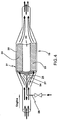
- FIG. 4 depicts an engine exhaust system 19 comprising a honeycomb structure 20 having an inlet and outlet end disposed in a housing 21 and located in an exhaust gas stream downstream from an engine (not shown).
- the honeycomb structure 20 possesses a first substantially unobstructed flow region 22, and a second more obstructed flow region 23 adjacent the first region, the first region being disposed to provide a substantially unobstructed flow path for the exhaust gases in the exhaust gas stream.
- the honeycomb structure is a substantially cellular structure having an open region running longitudinally parallel between the inlet and outlet ends of the structure and a peripheral region adjacent the open region, the peripheral region having a plurality of cells running longitudinally parallel between the inlet and the outlet ends of the structure.
- the honeycomb structure is centrally disposed in the housing and exhibits a central, open-core first region and a peripheral, cellular second region; preferably, the central region occupying an area in the range of 0.5 to 50% of the frontal area of the honeycomb structure.
- honeycomb structure utilized in this exhaust system could also be comprised of a variable cell honeycomb structure wherein the first region has a first group of cells and a second region has a second group of cells whose cell sizes are smaller than the first group of cells.
- the system further includes a fluidics apparatus 24, disposed in the exhaust stream comprised of the following elements: (1) a diverter body 25; (2) a diversion fluid source (not shown); (3) a conduit 26 for directing the diversion fluid toward the diverter body 25; and (4) an exhaust flow divergent device 27.
- the diverter body 25 is located proximate to inlet of the first or low flow resistance region 22.
- Each of these exhaust flow divergent devices, 28, 29 and 30, serve to direct the incoming flow of exhaust gases toward the peripheral or higher flow resistance region, thereby increasing the uniformity of the exhaust gas which enters the peripheral region of the honeycomb substrate.
- the divergent devices 28, 29 and 30, as illustrated, possesses a small diameter upstream portion 31, a large diameter downstream portion 32, and a side surface 33 connecting the two portions.
- the diameter of the larger portion should be smaller than the diameter exhibited by the low-flow resistance region; this allows for a more efficient and workable flow volume (> ⁇ 60%) through the low flow resistance or hole region under diverter-off conditions.
- the side surfaces exhibit a divergent angle ( ⁇ ), defined as the angle formed between the side surface and a reference plane perpendicular to the direction of the exhaust flow, of between about 45 and 75°; more preferably between about 60 to 75°.
- the fluidics apparatus 24 depicted therein is comprised of a round flat plate diverter body 25, a conduit 26 for directing a diversion fluid (not shown) toward the diverter body 25, with the conduit and diverter combining to form a slot 34 through which the diversion fluid is directed. Additionally, the fluidics apparatus 24 includes a cone-shaped exhaust flow divergent device 28.
- the fluidics apparatus embodiment depicted therein is again comprised of a round flat plate diverter body 25 and a conduit 26 for directing a diversion fluid (not shown) toward the diverter body 25; the conduit and diverter combining to form slot 28 through which the diversion fluid may be directed.
- the exhaust flow divergent device in this embodiment is comprised of trumpet-like shaped exhaust flow divergent device 29.
- the fluidics apparatus embodiment depicted therein is again comprised of a round flat plate diverter body 25, a conduit 26 for directing a diversion fluid (not shown) toward the diverter body 25; the conduit and diverter configured to form slot 28.
- the exhaust flow divergent device in this further embodiment is comprised of bell-shaped exhaust flow divergent device 30. It should be noted that the sides of the bell-shaped divergent device depicted herein are modified to include channels 35 which result in an increased flow volume through the low-flow resistance region under diverter-off conditions; a feature which may be added to either the cone or trumpet-shaped devices as well.
- this exhaust system configuration possesses other desirable attributes as follows: (1) a resultant, more effective use of the honeycomb surface area, e.g., in those applications wherein the substrate is a catalyst, more catalyst surface area is effectively utilized resulting in more efficient catalyzation; (2) a negative flow, or low positive flow of less than about 20% of total exhaust, in the low flow resistance region, during "diverter on” conditions; (3) a "diverter-off” flow through the low-flow resistance region of approximately greater than about 60% of the total exhaust flow volume; (4) a fluidics apparatus configuration, comprised of the diversion body and the divergent device, which produces minimum back pressure in the system.
- this fluidics apparatus described above and shown in examples below has utility as part of an overall in-line exhaust system like that disclosed in the aforementioned Hertl et al. reference, i.e., the honeycomb substrate disclosed hereinabove would be comprised of a molecular sieve or hydrocarbon adsorber.
- this in-line exhaust system includes the following:
- this "in-line" system is configured such that, during “diverter-on” operation, the diverter body, the diversion air and the exhaust gas divergent device combine to divert most of the exhaust through the honeycomb periphery containing the molecular sieves; either a uniformly distributed flow or a flow profile such that the higher flow occurs through the cells away from the low-flow resistance region.
- the system is configured to provide maximum adsorption of hydrocarbons; i.e., a negative flow or low positive flow of less than 20% of total exhaust should pass through the center hole.
- this "in-line” system achieves a better utilization of the entire adsorptive surface; i.e., better hydrocarbon adsorption.
- a more uniform or increased peripheral flow in those adsorber applications helps to avoid premature desorption by causing more adsorption to occur away from the low-flow resistance or hole region; since the regions closer to the central region typically heat up faster than those peripheral regions more distant from the center, they tend to desorb faster, sometimes prior than the lightoff of the burn-off catalyst.
- a “molecular sieve” as used herein refers to crystalline substances or structures having pore sizes suitable for adsorbing molecules. In general, this term is used to a class of materials that exhibit selective absorption properties; i.e., they separate components of a mixture on the basis of molecular size and shape differences. Such materials include silicates, the metallosilicates, metalloaluminates, the AlPO 4 s, silico- and metalloaluminophosphates, zeolites and the like. Furthermore, the terms “adsorber” and “adsorption” as used herein are intended to encompass both adsorption and absorption; it is contemplated that both processes may occur in the molecular sieve structure of the invention.
- the honeycomb substrate comprises a molecular sieve structure
- it preferably, comprises zeolites supported on the honeycomb structure, with the zeolites selected from the group consisting of ZSM-5, USY, Mordenite, Beta zeolites and combinations of these.
- the molecular sieve structure may comprise an extruded zeolite selected from the same zeolite group .
- the exhaust system configurations were comprised of the following components: (1) a cylindrical 400 cell per square inch (cpsi) honeycomb structure exhibiting a 11.85 cm diameter and a 3.81 cm diameter central hole region; and, (2) a fluidics apparatus comprised of the following: (a) a straight tube conduit positioned proximate to the honeycomb substrate's hole region, exhibiting a minimum outside diameter of 1.59 cm., for delivering the diversion fluid; and, (b) either a cone or trumpet-shaped exhaust flow divergent device having a variable divergent angle ( ⁇ x ), a 1.27 cm.
- a cylindrical 400 cell per square inch (cpsi) honeycomb structure exhibiting a 11.85 cm diameter and a 3.81 cm diameter central hole region
- a fluidics apparatus comprised of the following: (a) a straight tube conduit positioned proximate to the honeycomb substrate's hole region, exhibiting a minimum outside diameter of 1.59 cm., for delivering the diversion fluid; and, (b) either a cone or trumpet
- FIG. 11 illustrated therein is graphical representation of the simulated "diverter-on" exhaust flow profile exhibited by the Example 6 exhaust system configuration (60° cone-shaped exhaust gas divergent device); the honeycomb substrate and low-flow resistance region images are seen superimposed on the flow profile.
- This flow profile is representative of the typical uniformly distributed flow achieved through the utilization of a cone-shaped exhaust gas divergent device; a negative flow in the first or central flow region and a uniformly distributed, positive flow volume in the peripheral cells.
- FIG. 12 illustrated therein is graphical representation of simulated "diverter-on" exhaust gas flow profile exhibited by Example 2 exhaust system configuration (45° trumpet-shaped exhaust gas divergent device); the honeycomb substrate and low-flow resistance region images are again seen superimposed on the profile.
- This flow profile is representative of the typical, uniformly distributed flow achieved through the utilization of a trumpet-shaped exhaust gas divergent device; a negative flow in the first or central flow region and a high, uniformly distributed positive flow volume in the peripheral cells.
- this comparison exhaust system configuration was comprised of the following: (1) an 11.83 cm. diameter, 400 cell per square inch (cpsi) cylindrical honeycomb structure possessing a 3.81 cm. diameter centrally-located round first or low flow resistance region and, (2) a fluidics apparatus comprised of a 19 mm diameter round diverter body positioned proximate to the honeycomb substrate's hole region approximately 9 mm upstream of the inlet face of the honeycomb substrate and approximately 1 mm.
- FIG. 3 illustrated therein is a graphical representation of the simulated "diverter-on" exhaust flow profile exhibited by the comparison exhaust gas system configuration of Example 9; as above, the honeycomb substrate and low-flow resistance region images superimposed on the profile.
- This flow profile is representative of the non-uniform flow achieved without the use of an exhaust gas divergent device; a negative flow in the central or first flow region and a high, though non-uniformly distributed flow volume in the periphery (highest flow in the cells nearest the central region).
- the present invention has utility in a variety of systems for treating gas or other fluid streams, including any system wherein the handling of gas flows without the use of mechanical valves or other mechanical means of flow control is required.
- the systems of most immediate interest for such use are those involving the treatment of exhaust emissions from engines or other combustion exhaust gas sources. Accordingly, the preceding detailed description of the invention focused principally on such emissions control applications even though the use of the invention is not limited thereto.
- the invention has been described with respect to the above illustrated description and examples, it may be subjected to various modifications and changes without departing from the scope of the invention.
- the examples have utilized only square cell channels, the invention can be extended to a variety of cell shapes for the honeycomb, (triangular, hexagonal, rectangular, flexible cells etc.).
- the above description describes the exhaust system as comprised of circular honeycombs it is appreciated that by suitably contouring the maximum diameter of the diverter body, the diversion fluid can be spread unevenly to direct exhaust gas through honeycombs of non circular cross-section, such as elliptical substrates.
Landscapes
- Engineering & Computer Science (AREA)
- Chemical & Material Sciences (AREA)
- Combustion & Propulsion (AREA)
- Mechanical Engineering (AREA)
- General Engineering & Computer Science (AREA)
- Chemical Kinetics & Catalysis (AREA)
- Health & Medical Sciences (AREA)
- Toxicology (AREA)
- Exhaust Gas After Treatment (AREA)
- Exhaust Gas Treatment By Means Of Catalyst (AREA)
- Exhaust Silencers (AREA)
Applications Claiming Priority (2)
| Application Number | Priority Date | Filing Date | Title |
|---|---|---|---|
| US1301596P | 1996-03-07 | 1996-03-07 | |
| US13015 | 1996-03-07 |
Publications (1)
| Publication Number | Publication Date |
|---|---|
| EP0794325A1 true EP0794325A1 (de) | 1997-09-10 |
Family
ID=21757880
Family Applications (1)
| Application Number | Title | Priority Date | Filing Date |
|---|---|---|---|
| EP97103206A Ceased EP0794325A1 (de) | 1996-03-07 | 1997-02-27 | Abgas-Fluidik-Gerät |
Country Status (4)
| Country | Link |
|---|---|
| EP (1) | EP0794325A1 (de) |
| JP (1) | JPH102218A (de) |
| KR (1) | KR970065985A (de) |
| BR (1) | BR9701216A (de) |
Cited By (3)
| Publication number | Priority date | Publication date | Assignee | Title |
|---|---|---|---|---|
| EP1857172A1 (de) * | 2006-05-15 | 2007-11-21 | Sulzer Chemtech AG | Statikmischer |
| EP2130603A3 (de) * | 2008-05-20 | 2010-02-24 | Ibiden Co., Ltd. | Wabenstruktur |
| US8061890B2 (en) | 2006-05-15 | 2011-11-22 | Sulzer Chemtech Ag | Static mixer |
Citations (5)
| Publication number | Priority date | Publication date | Assignee | Title |
|---|---|---|---|---|
| DE3803917A1 (de) * | 1988-02-09 | 1989-08-17 | Interatom | Wabenfoermiger katalysator-traegerkoerper mit vergleichmaessigter anstroemung |
| DE3913343A1 (de) * | 1989-04-22 | 1990-10-25 | Kugelfischer G Schaefer & Co | Haltehilfshuelse fuer rollen- und nadellager |
| EP0661098A2 (de) * | 1993-12-28 | 1995-07-05 | Ngk Insulators, Ltd. | Abgasreinigung |
| WO1995018292A1 (en) * | 1993-12-30 | 1995-07-06 | Ab Volvo | An exhaust gas purification device |
| EP0697505A1 (de) * | 1994-08-02 | 1996-02-21 | Corning Incorporated | Adsorptionsvorrichtung in Reihe |
-
1997
- 1997-02-27 EP EP97103206A patent/EP0794325A1/de not_active Ceased
- 1997-03-06 JP JP9051739A patent/JPH102218A/ja not_active Withdrawn
- 1997-03-06 KR KR1019970007457A patent/KR970065985A/ko not_active Application Discontinuation
- 1997-03-06 BR BR9701216A patent/BR9701216A/pt not_active Application Discontinuation
Patent Citations (5)
| Publication number | Priority date | Publication date | Assignee | Title |
|---|---|---|---|---|
| DE3803917A1 (de) * | 1988-02-09 | 1989-08-17 | Interatom | Wabenfoermiger katalysator-traegerkoerper mit vergleichmaessigter anstroemung |
| DE3913343A1 (de) * | 1989-04-22 | 1990-10-25 | Kugelfischer G Schaefer & Co | Haltehilfshuelse fuer rollen- und nadellager |
| EP0661098A2 (de) * | 1993-12-28 | 1995-07-05 | Ngk Insulators, Ltd. | Abgasreinigung |
| WO1995018292A1 (en) * | 1993-12-30 | 1995-07-06 | Ab Volvo | An exhaust gas purification device |
| EP0697505A1 (de) * | 1994-08-02 | 1996-02-21 | Corning Incorporated | Adsorptionsvorrichtung in Reihe |
Cited By (3)
| Publication number | Priority date | Publication date | Assignee | Title |
|---|---|---|---|---|
| EP1857172A1 (de) * | 2006-05-15 | 2007-11-21 | Sulzer Chemtech AG | Statikmischer |
| US8061890B2 (en) | 2006-05-15 | 2011-11-22 | Sulzer Chemtech Ag | Static mixer |
| EP2130603A3 (de) * | 2008-05-20 | 2010-02-24 | Ibiden Co., Ltd. | Wabenstruktur |
Also Published As
| Publication number | Publication date |
|---|---|
| JPH102218A (ja) | 1998-01-06 |
| KR970065985A (ko) | 1997-10-13 |
| BR9701216A (pt) | 1999-02-09 |
Similar Documents
| Publication | Publication Date | Title |
|---|---|---|
| US5941068A (en) | Automotive hydrocarbon adsorber system | |
| EP0781903A1 (de) | Abgasströmungsvorrichtung | |
| US5916133A (en) | Automotive hydrocarbon adsorber system | |
| EP1969214B1 (de) | Abgassystem umfassend einen in zonen unterteilten oxidationskatalysator | |
| EP0585572B1 (de) | Vorrichtung und Verfahren zur Änderung einer Gasmischung | |
| EP3081777B1 (de) | Abgasreinigungsmaterial | |
| US5771684A (en) | Gas treatment systems | |
| US6274106B1 (en) | Oxide gas absorbing arrangement and method | |
| EP0661098A2 (de) | Abgasreinigung | |
| CA2054462A1 (en) | Heater and Catalytic Converter | |
| GB2342055A (en) | Exhaust treatment device with varying cell density | |
| US6641785B1 (en) | Catalytic converter and method for cleaning exhaust gas | |
| US20030012707A1 (en) | Exhaust gas purifying system | |
| US6808686B1 (en) | Spark-ignited internal combustion engine oxide gas absorbing arrangement and method | |
| US5619853A (en) | Exhaust system with a fluidics apparatus diverter body having extensions | |
| JP2005120909A (ja) | 内燃機関の排気浄化装置 | |
| US5850734A (en) | Close-coupled catalytic converter system | |
| EP0780549A1 (de) | Abgassystem mit einer Unterdruckströmungsvorrichtung | |
| US5890361A (en) | Exhaust gas fluidics apparatus | |
| EP0794325A1 (de) | Abgas-Fluidik-Gerät | |
| JP4042903B2 (ja) | ガスフローの触媒処理装置 | |
| US6171557B1 (en) | System for exhaust gas purification | |
| JP2007218177A (ja) | 排ガス浄化システム | |
| JP3304678B2 (ja) | 内燃機関の排気浄化装置 | |
| CN209586472U (zh) | 载体、集成颗粒物捕集的三元催化器以及车辆 |
Legal Events
| Date | Code | Title | Description |
|---|---|---|---|
| PUAI | Public reference made under article 153(3) epc to a published international application that has entered the european phase |
Free format text: ORIGINAL CODE: 0009012 |
|
| AK | Designated contracting states |
Kind code of ref document: A1 Designated state(s): DE FR GB IT |
|
| 17P | Request for examination filed |
Effective date: 19980128 |
|
| 17Q | First examination report despatched |
Effective date: 19991201 |
|
| GRAG | Despatch of communication of intention to grant |
Free format text: ORIGINAL CODE: EPIDOS AGRA |
|
| STAA | Information on the status of an ep patent application or granted ep patent |
Free format text: STATUS: THE APPLICATION HAS BEEN REFUSED |
|
| 18R | Application refused |
Effective date: 20011203 |