EP0794084A2 - Vehicle traction with variable throttle gain - Google Patents
Vehicle traction with variable throttle gain Download PDFInfo
- Publication number
- EP0794084A2 EP0794084A2 EP96309352A EP96309352A EP0794084A2 EP 0794084 A2 EP0794084 A2 EP 0794084A2 EP 96309352 A EP96309352 A EP 96309352A EP 96309352 A EP96309352 A EP 96309352A EP 0794084 A2 EP0794084 A2 EP 0794084A2
- Authority
- EP
- European Patent Office
- Prior art keywords
- throttle angle
- angle position
- wheel slip
- transfer function
- commanded
- Prior art date
- Legal status (The legal status is an assumption and is not a legal conclusion. Google has not performed a legal analysis and makes no representation as to the accuracy of the status listed.)
- Withdrawn
Links
- 230000007704 transition Effects 0.000 claims abstract description 7
- 238000012546 transfer Methods 0.000 claims description 20
- 238000000034 method Methods 0.000 claims description 10
- 238000002485 combustion reaction Methods 0.000 claims description 4
- 230000003068 static effect Effects 0.000 claims description 4
- 230000005540 biological transmission Effects 0.000 claims description 3
- 230000000295 complement effect Effects 0.000 claims description 3
- 230000000694 effects Effects 0.000 abstract description 3
- 230000009467 reduction Effects 0.000 abstract description 2
- 238000010586 diagram Methods 0.000 description 3
- 208000033986 Device capturing issue Diseases 0.000 description 2
- 239000010426 asphalt Substances 0.000 description 2
- 238000012360 testing method Methods 0.000 description 2
- 238000013459 approach Methods 0.000 description 1
- 230000008859 change Effects 0.000 description 1
- 238000006243 chemical reaction Methods 0.000 description 1
- 239000000446 fuel Substances 0.000 description 1
- 238000002347 injection Methods 0.000 description 1
- 239000007924 injection Substances 0.000 description 1
- 238000013507 mapping Methods 0.000 description 1
- 238000012986 modification Methods 0.000 description 1
- 230000004048 modification Effects 0.000 description 1
- 230000004044 response Effects 0.000 description 1
- 238000004088 simulation Methods 0.000 description 1
Images


Classifications
-
- B—PERFORMING OPERATIONS; TRANSPORTING
- B60—VEHICLES IN GENERAL
- B60K—ARRANGEMENT OR MOUNTING OF PROPULSION UNITS OR OF TRANSMISSIONS IN VEHICLES; ARRANGEMENT OR MOUNTING OF PLURAL DIVERSE PRIME-MOVERS IN VEHICLES; AUXILIARY DRIVES FOR VEHICLES; INSTRUMENTATION OR DASHBOARDS FOR VEHICLES; ARRANGEMENTS IN CONNECTION WITH COOLING, AIR INTAKE, GAS EXHAUST OR FUEL SUPPLY OF PROPULSION UNITS IN VEHICLES
- B60K28/00—Safety devices for propulsion-unit control, specially adapted for, or arranged in, vehicles, e.g. preventing fuel supply or ignition in the event of potentially dangerous conditions
- B60K28/10—Safety devices for propulsion-unit control, specially adapted for, or arranged in, vehicles, e.g. preventing fuel supply or ignition in the event of potentially dangerous conditions responsive to conditions relating to the vehicle
- B60K28/16—Safety devices for propulsion-unit control, specially adapted for, or arranged in, vehicles, e.g. preventing fuel supply or ignition in the event of potentially dangerous conditions responsive to conditions relating to the vehicle responsive to, or preventing, spinning or skidding of wheels
-
- B—PERFORMING OPERATIONS; TRANSPORTING
- B60—VEHICLES IN GENERAL
- B60W—CONJOINT CONTROL OF VEHICLE SUB-UNITS OF DIFFERENT TYPE OR DIFFERENT FUNCTION; CONTROL SYSTEMS SPECIALLY ADAPTED FOR HYBRID VEHICLES; ROAD VEHICLE DRIVE CONTROL SYSTEMS FOR PURPOSES NOT RELATED TO THE CONTROL OF A PARTICULAR SUB-UNIT
- B60W50/00—Details of control systems for road vehicle drive control not related to the control of a particular sub-unit, e.g. process diagnostic or vehicle driver interfaces
- B60W2050/0001—Details of the control system
- B60W2050/0002—Automatic control, details of type of controller or control system architecture
- B60W2050/0008—Feedback, closed loop systems or details of feedback error signal
- B60W2050/0011—Proportional Integral Differential [PID] controller
-
- B—PERFORMING OPERATIONS; TRANSPORTING
- B60—VEHICLES IN GENERAL
- B60W—CONJOINT CONTROL OF VEHICLE SUB-UNITS OF DIFFERENT TYPE OR DIFFERENT FUNCTION; CONTROL SYSTEMS SPECIALLY ADAPTED FOR HYBRID VEHICLES; ROAD VEHICLE DRIVE CONTROL SYSTEMS FOR PURPOSES NOT RELATED TO THE CONTROL OF A PARTICULAR SUB-UNIT
- B60W50/00—Details of control systems for road vehicle drive control not related to the control of a particular sub-unit, e.g. process diagnostic or vehicle driver interfaces
- B60W2050/0001—Details of the control system
- B60W2050/0019—Control system elements or transfer functions
- B60W2050/0022—Gains, weighting coefficients or weighting functions
Definitions
- This invention relates to a method of controlling traction for a vehicle.
- Traction control of various types is known. For example, it is known to reduce the power applied to the driving wheels through various combinations of controlling engine operating parameters such as spark advance, fuel injection, and throttle control. Braking may also be used to control driving wheel rotation.
- a method of controlling traction for a vehicle having an internal combustion engine including the step of linearising the relationship between powertrain torque versus throttle angle position in order to improve traction control by reducing spin during a dry road to ice transition when the traction control is initiated already on dry road or other similar large road friction changes.
- An embodiment of this invention uses simple empirically or simulation generated engine and powertrain torque measured, for example, at the driving wheel versus throttle angle position data to in effect linearise the relationship.
- the results are improved traction control through substantial reduction, by factor 2 or 3, of a spin during, for example, dry road to ice transition when the traction control is initiated already on the dry road.
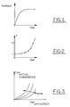
- FIG. 1 A typical, steady-state relations between engine or powertrain torque and throttle angle position (TAP) for a given rpm is shown in Fig. 1. It can be seen that for larger TAP's, above some mid-region, large TAP changes are needed for a given delta torque change.
- Fig. 4A the time versus wheel speed of a vehicle including an embodiment of this invention is shown and in Fig. 4B a graphic presentation of time versus throttle angle position is shown.
- a method for improved throttle control through an effective static linearisation starts at a start block 30.
- Object flow from block 30 goes to block 31 where there is calculated a throttle angle position from slip error based algorithm.
- Logic flow from block 31 goes to a block 32 wherein there is Performed a static linearisation in accordance with the embodiment of this invention and a calculated commanded throttle angle position as calculated.
- Logic flow from block 32 goes to a decision block 33 wherein it is asked if the throttle angle position commanded is less than or equal to the throttle angle position minimum. If yes, then the throttle command is clipped at throttle minimum opening at block 34.
- Logic flow from block 34 goes to a decision from block 35. Also, if at decision block 33 the answer is no, logic flow goes to decision block 35.
- a summer 40 receives an input from desired slip coefficient in percent slip or, alternatively, in an equivalent rpm wheel speed, and receives a negative input of actual slip.
- An error output from summer 40 is applied to a proportional - integral- derivative (PID) controller 41 which then applies an output signal to a filter 42 to produce a calculated throttle angle position.
- PID proportional - integral- derivative
- Such calculated throttle angle position is applied to a transfer function 43 which then generates a commanded throttle angle position that can be applied to the engine.
- Transfer function 43 can be a table which is experimentally obtained as a steady-state relation between wheel torque and the throttle position where the wheel torque includes engine, torque conversion for automatic transmission and driveline transfer functions.
- Engine revolutions per minute can also be used as a parameter so as to develop a transfer function curve for each rpm.
- the transfer function is selected to be an inverse complement of the transfer function of the engine and the powertrain being controlled.
- the control system linearisation block 43 and engine combination has linear operation. Such linear operation is advantageous because it is easier to control.
- the transfer function connection shown in Fig. 7 can also include wheel slip.
- a block 44 has as inputs the output of block 43 and an indication of slip.
- the output of block 43 is used to control the throttle angle position and the operation of the powertrain plant.
- the transfer function of block 44 relates slip to throttle angle position.
- the combination of the transfer functions of block 43 and 44 can be considered to linearise the total powertrain transfer function of a vehicle including the engine, transmission, axle and wheels.
- the desired slip in the actual slip were applied to a summer 50 then applied to a PID controller 51 and then applied to a filter 52.
- the output of the filter 52 was the calculatable command at throttle angle position.
- the prior art did not include anything corresponding to block 43 and block 44 wherein the transfer function between the effective throttle angle position and the actual commanded throttle angle position is arrived at based on aforementioned empirical data.
Landscapes
- Engineering & Computer Science (AREA)
- Chemical & Material Sciences (AREA)
- Combustion & Propulsion (AREA)
- Transportation (AREA)
- Mechanical Engineering (AREA)
- Control Of Vehicle Engines Or Engines For Specific Uses (AREA)
- Electrical Control Of Air Or Fuel Supplied To Internal-Combustion Engine (AREA)
Abstract
Description
- This invention relates to a method of controlling traction for a vehicle.
- Traction control of various types is known. For example, it is known to reduce the power applied to the driving wheels through various combinations of controlling engine operating parameters such as spark advance, fuel injection, and throttle control. Braking may also be used to control driving wheel rotation.
- Even though such control of the driving wheels is known, there still is a need to improve the performance of traction control in various operating environments. Conditions such as sudden transition from large coefficient of friction to low coefficient of friction surfaces are addressed by this invention.
- According to the present invention, there is provided a method of controlling traction for a vehicle having an internal combustion engine including the step of linearising the relationship between powertrain torque versus throttle angle position in order to improve traction control by reducing spin during a dry road to ice transition when the traction control is initiated already on dry road or other similar large road friction changes.
- An embodiment of this invention uses simple empirically or simulation generated engine and powertrain torque measured, for example, at the driving wheel versus throttle angle position data to in effect linearise the relationship. The results are improved traction control through substantial reduction, by
factor - Application of the embodiment of this invention can lead to a substantially shorter and improved system response for situations where the spin has been initiated already on the dry road which subsequently changes to ice. Originally, without the proposed feature, the dry to ice spin duration was about 2 or 3 seconds. However, in accordance with this invention, the spin has been reduced to around 1 second.
- The invention will now be described further, by way of example, with reference to the accompanying drawings, in which:
- Fig. 1 is a graphic representation of throttle angle position versus powertrain torque;
- Fig. 2 is a graphic representation of throttle angle position versus a throttle gain factor;
- Fig. 3 is a graphic representation of effective throttle angle position versus throttle angle position which is actual and commanded, as a function of engine rpm;
- Fig. 4A and 4B are graphic representations of time versus wheel speed and time versus throttle angle position during a dry asphalt to ice transition test in accordance with an embodiment of this invention;
- Figs. 5A and 5B are graphic representations of time versus wheel speed and time versus throttle angle position during a dry asphalt to ice transition test in accordance with the prior art;
- Fig. 6 is a logic flow diagram in accordance with an embodiment of this invention;
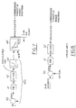
- Fig. 7 is a block diagram in accordance with an embodiment of this invention; and
- Fig. 8 is a block diagram in accordance with the prior art of a traction control system.
- A typical, steady-state relations between engine or powertrain torque and throttle angle position (TAP) for a given rpm is shown in Fig. 1. It can be seen that for larger TAP's, above some mid-region, large TAP changes are needed for a given delta torque change.
- To linearise the above relationship statically one can proceed as follows:
- (a) Introduce a variable gain factor f(Fig. 2) that will multiply the incremental control signal (ΔMK).
- (b) Use the concept of "effective TAP" as illustrated in Fig. 3. Essentially, one uses an inverse mapping for Fig. 1. If desired, this can be refined by rpm dependence.
- (c) When either approach (a) or (b) are used, with the series throttle implementation, then ideally the resulting TP actual/commanded should be further translated into corresponding secondary throttle as per our previous invention disclosure.
- Referring to Fig. 4A, the time versus wheel speed of a vehicle including an embodiment of this invention is shown and in Fig. 4B a graphic presentation of time versus throttle angle position is shown.
- Referring to Figs. 5A and 5B, in accordance with the prior art, the time versus wheel speed and the time versus throttle angle position is shown.
- In summary, note from Figs. 4A and 5A that while the initial spin, on dry road, was about the same for both implementations, the subsequent spin on ice, around time=2 sec., was much shorter with the present invention. This is the consequence of the fact that the throttle has been much more aggressively closed with the proposed method as it can be seen from Fig. 4B (compare with Fig. 5B).
- Referring to Fig. 6, a method for improved throttle control through an effective static linearisation starts at a
start block 30. Object flow fromblock 30 goes toblock 31 where there is calculated a throttle angle position from slip error based algorithm. Logic flow fromblock 31 goes to ablock 32 wherein there is Performed a static linearisation in accordance with the embodiment of this invention and a calculated commanded throttle angle position as calculated. Logic flow fromblock 32 goes to adecision block 33 wherein it is asked if the throttle angle position commanded is less than or equal to the throttle angle position minimum. If yes, then the throttle command is clipped at throttle minimum opening atblock 34. Logic flow fromblock 34 goes to a decision fromblock 35. Also, if atdecision block 33 the answer is no, logic flow goes todecision block 35. Atdecision block 35 it is asked if the commanded throttle angle position is greater than or equal than the maximum throttle angle position. If yes, logic flow goes to ablock 36 wherein the commanded throttle angle position is set equal to the maximum angle position. Logic flow then goes to anexit block 37. If atdecision block 35 the answer is no, logic flow goes toexit block 37. - Referring to Fig. 7, a
summer 40 receives an input from desired slip coefficient in percent slip or, alternatively, in an equivalent rpm wheel speed, and receives a negative input of actual slip. An error output fromsummer 40 is applied to a proportional - integral- derivative (PID)controller 41 which then applies an output signal to afilter 42 to produce a calculated throttle angle position. Such calculated throttle angle position is applied to atransfer function 43 which then generates a commanded throttle angle position that can be applied to the engine.Transfer function 43 can be a table which is experimentally obtained as a steady-state relation between wheel torque and the throttle position where the wheel torque includes engine, torque conversion for automatic transmission and driveline transfer functions. Engine revolutions per minute (rpm) can also be used as a parameter so as to develop a transfer function curve for each rpm. The transfer function is selected to be an inverse complement of the transfer function of the engine and the powertrain being controlled. As a result, during operation of traction control, the controlsystem linearisation block 43 and engine combination has linear operation. Such linear operation is advantageous because it is easier to control. - If desired the transfer function connection shown in Fig. 7 can also include wheel slip. As shown, a
block 44 has as inputs the output ofblock 43 and an indication of slip. The output ofblock 43 is used to control the throttle angle position and the operation of the powertrain plant. The transfer function ofblock 44 relates slip to throttle angle position. The combination of the transfer functions ofblock - Instead of the inverse relations, of
block 43, one could use the non-linear gain functions, f, shown in Fig. 2, which is derived based on a slope or derivative to the throttle torque curve of Fig. 1. Similar gain function, ft, could also be used to effectively linearise the tire slip versus force or torque relationship. This is shown asblock 44 in Fig. 7. - Referring to Fig. 8, in accordance with the prior art, the desired slip in the actual slip were applied to a
summer 50 then applied to aPID controller 51 and then applied to afilter 52. The output of thefilter 52 was the calculatable command at throttle angle position. Or specifically, the prior art did not include anything corresponding to block 43 and block 44 wherein the transfer function between the effective throttle angle position and the actual commanded throttle angle position is arrived at based on aforementioned empirical data. - Various modifications and variations, including possible alternatives for the above PID controller, will no doubt occur to those skilled in the arts to which this invention pertains. Such variations including non-linear inverse dynamic effects which rely upon the teachings through which disclosure has advanced the art are properly considered within the scope of these claims.
Claims (6)
- A method of controlling traction for a vehicle having an internal combustion engine including the step of linearising the relationship between powertrain torque versus throttle angle position in order to improve traction control by reducing spin during a dry road to ice transition when the traction control is initiated already on dry road or other similar large road friction changes.
- A method of controlling traction as claimed in claim 1, wherein the step of linearising the relationship between powertrain torque versus throttle angle includes adding a transfer function having an inverse complementary characteristic to such relationship so as to linearise the transfer function for developing throttle angle position as a function of wheel slip in excess of a predetermined amount of slip.
- A method of controlling traction as claimed in claim 1, wherein the step of linearising the relationship between powertrain torque versus throttle angle includes adding a transfer function having an inverse complementary characteristic to a transfer function characterising wheel slip versus throttle angle position.
- A method of controlling traction for a vehicle having an internal combustion engine with electronically controlled operating parameters, including the steps of:determining wheel slip error;calculating throttle angle position based on wheel slip error;performing static linearisation of a throttle angle position to torque transfer function in view of the engine and powertrain non-linearities;calculating commanded throttle angle position;establishing a predetermined minimum throttle angle position and a predetermined maximum throttle angle position;determining if the commanded throttle angle position is less than the predetermined minimum throttle angle position;if yes, setting commanded throttle angle position equal to the predetermined minimum throttle angle;if no, determining if the commanded throttle angle position is greater than the predetermined maximum throttle angle position; andif the commanded throttle angle position is greater than the predetermined maximum throttle angle position, then setting the commanded throttle angle position equal to the predetermined maximum throttle angle position.
- A method of controlling traction as claimed in claim 4, wherein the step of performing static linearisation of a throttle angle position transfer function includes developing a table for each of a plurality of engine speeds, and in the use of automatic transmissions, torque converter speed ratios, said table relating powertrain torque and throttle angle so that the total transfer function of the table and the internal combustion engine and powertrain is a linear transfer function, thus making traction control easier.
- A method of controlling traction as claimed in claim 5, further comprising the steps of:establishing a desired amount of wheel slip;detecting actual wheel slip;determining an error wheel slip by comparing the actual and desired amount of wheel slip;processing the error wheel slip using a proportional - integral - derivative controller and a filter to develop a processed error wheel slip signal; andapplying the throttle angle position transfer function to the processed error wheel slip signal.
Applications Claiming Priority (2)
| Application Number | Priority Date | Filing Date | Title |
|---|---|---|---|
| US08/610,939 US5749428A (en) | 1996-03-05 | 1996-03-05 | Traction control through an effective static linearization |
| US610939 | 1996-03-05 |
Publications (2)
| Publication Number | Publication Date |
|---|---|
| EP0794084A2 true EP0794084A2 (en) | 1997-09-10 |
| EP0794084A3 EP0794084A3 (en) | 1999-01-13 |
Family
ID=24447006
Family Applications (1)
| Application Number | Title | Priority Date | Filing Date |
|---|---|---|---|
| EP96309352A Withdrawn EP0794084A3 (en) | 1996-03-05 | 1996-12-20 | Vehicle traction with variable throttle gain |
Country Status (2)
| Country | Link |
|---|---|
| US (1) | US5749428A (en) |
| EP (1) | EP0794084A3 (en) |
Family Cites Families (7)
| Publication number | Priority date | Publication date | Assignee | Title |
|---|---|---|---|---|
| DE3019562A1 (en) * | 1980-05-22 | 1981-11-26 | Daimler-Benz Ag, 7000 Stuttgart | DEVICE FOR CONTROLLING AN INTERNAL COMBUSTION ENGINE |
| DE3417089A1 (en) * | 1984-05-09 | 1985-11-14 | Robert Bosch Gmbh, 7000 Stuttgart | DRIVE CONTROL DEVICE |
| JPH0749786B2 (en) * | 1987-12-25 | 1995-05-31 | 日産自動車株式会社 | Vehicle drive force control device |
| GB2222702B (en) * | 1988-07-25 | 1993-03-10 | Nissan Motor | Wheel slippage suppresive throttle control system for automotive internal combustion engine |
| US5137105A (en) * | 1990-01-19 | 1992-08-11 | Honda Giken Kogyo Kabushiki Kaisha | System and method for controlling torque of driving wheel |
| GB9100224D0 (en) * | 1991-01-05 | 1991-02-20 | Lucas Ind Plc | Method of and apparatus for controlling wheel spin |
| DE4315885C1 (en) * | 1993-05-12 | 1994-11-03 | Daimler Benz Ag | Torque adjustment procedure |
-
1996
- 1996-03-05 US US08/610,939 patent/US5749428A/en not_active Expired - Fee Related
- 1996-12-20 EP EP96309352A patent/EP0794084A3/en not_active Withdrawn
Non-Patent Citations (1)
| Title |
|---|
| None |
Also Published As
| Publication number | Publication date |
|---|---|
| EP0794084A3 (en) | 1999-01-13 |
| US5749428A (en) | 1998-05-12 |
Similar Documents
| Publication | Publication Date | Title |
|---|---|---|
| US5403250A (en) | Arrangement for adjusting the clutch slip of a friction clutch arranged on the output side of a motor vehicle engine | |
| US8010272B2 (en) | Control device for internal combustion engine | |
| CN100422601C (en) | Lock-up control of torque converter | |
| US5628706A (en) | Method and arrangement for controlling the output power of a drive unit of a motor vehicle | |
| KR960013764A (en) | Power Train Control | |
| US4622865A (en) | Apparatus for controlling continuously variable transmission when accelerating from low speeds | |
| US4936405A (en) | Multiple feedback loop control method and system for controlling wheel slip | |
| US6460647B1 (en) | Slip control system | |
| JPH0327791B2 (en) | ||
| JP2000130239A (en) | Method and apparatus for controlling drag torque of internal combustion engine | |
| US5020622A (en) | Multiple feedback loop control method and system for controlling wheel slip | |
| US6418907B1 (en) | Method and device for the operation of a drive unit on a vehicle | |
| EP0794082B1 (en) | Method of operating a traction system for a vehicle | |
| US5107429A (en) | Adaptive throttle controller for vehicle traction control | |
| US6732036B2 (en) | Method and apparatus for controlling a drive unit | |
| US5749428A (en) | Traction control through an effective static linearization | |
| US5781876A (en) | Cruise control road speed control device, especially for a diesel-powered vehicle | |
| JP3709715B2 (en) | Vehicle driving force control device | |
| JP4488643B2 (en) | Method and apparatus for controlling vehicle drive unit | |
| CN116480773B (en) | Vehicle control devices | |
| JP3498579B2 (en) | System control unit | |
| JPH08145165A (en) | Control device for automatic transmission for vehicle | |
| JP2805061B2 (en) | Control system for vehicle drive train | |
| JP4082700B2 (en) | Slip control device for torque converter | |
| JP2001208193A (en) | Slip control device for torque converter |
Legal Events
| Date | Code | Title | Description |
|---|---|---|---|
| PUAI | Public reference made under article 153(3) epc to a published international application that has entered the european phase |
Free format text: ORIGINAL CODE: 0009012 |
|
| AK | Designated contracting states |
Kind code of ref document: A2 Designated state(s): AT DE FR GB |
|
| PUAL | Search report despatched |
Free format text: ORIGINAL CODE: 0009013 |
|
| AK | Designated contracting states |
Kind code of ref document: A3 Designated state(s): AT DE FR GB |
|
| 17P | Request for examination filed |
Effective date: 19990525 |
|
| 17Q | First examination report despatched |
Effective date: 20020614 |
|
| STAA | Information on the status of an ep patent application or granted ep patent |
Free format text: STATUS: THE APPLICATION IS DEEMED TO BE WITHDRAWN |
|
| 18D | Application deemed to be withdrawn |
Effective date: 20021025 |