EP0793988A2 - Filter for a motorized sweeper and related machine - Google Patents
Filter for a motorized sweeper and related machine Download PDFInfo
- Publication number
- EP0793988A2 EP0793988A2 EP97103007A EP97103007A EP0793988A2 EP 0793988 A2 EP0793988 A2 EP 0793988A2 EP 97103007 A EP97103007 A EP 97103007A EP 97103007 A EP97103007 A EP 97103007A EP 0793988 A2 EP0793988 A2 EP 0793988A2
- Authority
- EP
- European Patent Office
- Prior art keywords
- filter
- filtering element
- motor
- fins
- rotation
- Prior art date
- Legal status (The legal status is an assumption and is not a legal conclusion. Google has not performed a legal analysis and makes no representation as to the accuracy of the status listed.)
- Granted
Links
Images
Classifications
-
- A—HUMAN NECESSITIES
- A47—FURNITURE; DOMESTIC ARTICLES OR APPLIANCES; COFFEE MILLS; SPICE MILLS; SUCTION CLEANERS IN GENERAL
- A47L—DOMESTIC WASHING OR CLEANING; SUCTION CLEANERS IN GENERAL
- A47L9/00—Details or accessories of suction cleaners, e.g. mechanical means for controlling the suction or for effecting pulsating action; Storing devices specially adapted to suction cleaners or parts thereof; Carrying-vehicles specially adapted for suction cleaners
- A47L9/20—Means for cleaning filters
-
- A—HUMAN NECESSITIES
- A47—FURNITURE; DOMESTIC ARTICLES OR APPLIANCES; COFFEE MILLS; SPICE MILLS; SUCTION CLEANERS IN GENERAL
- A47L—DOMESTIC WASHING OR CLEANING; SUCTION CLEANERS IN GENERAL
- A47L9/00—Details or accessories of suction cleaners, e.g. mechanical means for controlling the suction or for effecting pulsating action; Storing devices specially adapted to suction cleaners or parts thereof; Carrying-vehicles specially adapted for suction cleaners
- A47L9/10—Filters; Dust separators; Dust removal; Automatic exchange of filters
- A47L9/12—Dry filters
- A47L9/127—Dry filters tube- or sleeve-shaped
-
- B—PERFORMING OPERATIONS; TRANSPORTING
- B01—PHYSICAL OR CHEMICAL PROCESSES OR APPARATUS IN GENERAL
- B01D—SEPARATION
- B01D46/00—Filters or filtering processes specially modified for separating dispersed particles from gases or vapours
- B01D46/24—Particle separators, e.g. dust precipitators, using rigid hollow filter bodies
- B01D46/2403—Particle separators, e.g. dust precipitators, using rigid hollow filter bodies characterised by the physical shape or structure of the filtering element
- B01D46/2411—Filter cartridges
-
- B—PERFORMING OPERATIONS; TRANSPORTING
- B01—PHYSICAL OR CHEMICAL PROCESSES OR APPARATUS IN GENERAL
- B01D—SEPARATION
- B01D46/00—Filters or filtering processes specially modified for separating dispersed particles from gases or vapours
- B01D46/24—Particle separators, e.g. dust precipitators, using rigid hollow filter bodies
- B01D46/26—Particle separators, e.g. dust precipitators, using rigid hollow filter bodies rotatable
-
- B—PERFORMING OPERATIONS; TRANSPORTING
- B01—PHYSICAL OR CHEMICAL PROCESSES OR APPARATUS IN GENERAL
- B01D—SEPARATION
- B01D46/00—Filters or filtering processes specially modified for separating dispersed particles from gases or vapours
- B01D46/52—Particle separators, e.g. dust precipitators, using filters embodying folded corrugated or wound sheet material
- B01D46/521—Particle separators, e.g. dust precipitators, using filters embodying folded corrugated or wound sheet material using folded, pleated material
-
- B—PERFORMING OPERATIONS; TRANSPORTING
- B01—PHYSICAL OR CHEMICAL PROCESSES OR APPARATUS IN GENERAL
- B01D—SEPARATION
- B01D46/00—Filters or filtering processes specially modified for separating dispersed particles from gases or vapours
- B01D46/66—Regeneration of the filtering material or filter elements inside the filter
- B01D46/68—Regeneration of the filtering material or filter elements inside the filter by means acting on the cake side involving movement with regard to the filter elements
- B01D46/681—Regeneration of the filtering material or filter elements inside the filter by means acting on the cake side involving movement with regard to the filter elements by scrapers, brushes or the like
-
- B—PERFORMING OPERATIONS; TRANSPORTING
- B01—PHYSICAL OR CHEMICAL PROCESSES OR APPARATUS IN GENERAL
- B01D—SEPARATION
- B01D46/00—Filters or filtering processes specially modified for separating dispersed particles from gases or vapours
- B01D46/66—Regeneration of the filtering material or filter elements inside the filter
- B01D46/74—Regeneration of the filtering material or filter elements inside the filter by forces created by movement of the filter element
- B01D46/76—Regeneration of the filtering material or filter elements inside the filter by forces created by movement of the filter element involving vibrations
-
- E—FIXED CONSTRUCTIONS
- E01—CONSTRUCTION OF ROADS, RAILWAYS, OR BRIDGES
- E01H—STREET CLEANING; CLEANING OF PERMANENT WAYS; CLEANING BEACHES; DISPERSING OR PREVENTING FOG IN GENERAL CLEANING STREET OR RAILWAY FURNITURE OR TUNNEL WALLS
- E01H1/00—Removing undesirable matter from roads or like surfaces, with or without moistening of the surface
- E01H1/08—Pneumatically dislodging or taking-up undesirable matter or small objects; Drying by heat only or by streams of gas; Cleaning by projecting abrasive particles
- E01H1/0827—Dislodging by suction; Mechanical dislodging-cleaning apparatus with independent or dependent exhaust, e.g. dislodging-sweeping machines with independent suction nozzles ; Mechanical loosening devices working under vacuum
-
- B—PERFORMING OPERATIONS; TRANSPORTING
- B01—PHYSICAL OR CHEMICAL PROCESSES OR APPARATUS IN GENERAL
- B01D—SEPARATION
- B01D2273/00—Operation of filters specially adapted for separating dispersed particles from gases or vapours
- B01D2273/30—Means for generating a circulation of a fluid in a filtration system, e.g. using a pump or a fan
Definitions
- the present invention relates to a filter for motorized sweepers, as well as to a machine with improved characteristics derived from the employment of the aforesaid filter.
- the motorized sweepers are used, for instance, for the cleaning of the road mantle, of the flooring in public buildings, factories, railways stations, etc.
- These machines generally comprise one or more rotating elements in contact with the ground, a system of dust aspiration, a filtration system and a chamber to collect the dust.
- a first type of filter consists of one or more panels of paper which are folded like an accordion to increase the filtering surface.
- a second type consists of bags containing filter material, and a third type comprises vertically disposed cylindrical cartridges inside of which is arranged an accordion-folded filtering element.
- a first problem of the known filters is their excessive encumbrance.
- a second problem is cleaning the filter efficiently. Cleaning is effected by jolting the same filter by hand or by machine. For instance, in the case of the vertical cylindrical cartridges filter a system is used that involves striking repeatedly the cartridge with a hammer or vibrator. This method presents however the problem that the dirt tends to stay in the lower parts of the filter, causing a reduction of efficiency of up to 2/3 in a short time.
- a further system for cleaning a panel filter for motorized sweeper by hand, using one or more combs attached to a frame, which are manually run along the surface of the panel.
- the purpose of the present invention is to resolve the aforementioned problems by means of a filter for motorized sweepers that is of limited encumbrance and is easy to clean.
- a further purpose of the present invention is to produce a motorized sweeper equipped with the aforesaid filter which would be less polluting, quieter, and more comfortable for the operator to use.
- a filter for motorized sweepers comprising a filter element, substantially cylindrical in shape and folded like an accordion to form a multiplicity of fins, an aspirator and a low pressure chamber to store the dust collected, characterized by providing a motor that sets said fins of said filtering element in relative movement with respect to at least one striker or a rigid or semirigid comb interfering with the fins, to effect the separation of the dust from the said filtering element through the flexing and elastic return to position of the same fins.
- the said filtering element has its axis of rotation in a substantially horizontal position and is set in rotation by the said motor so that the fins of the filtering element knock against at least one fixed rigid or semirigid comb.
- the said fins of the filtering element present themselves divergent and turned toward the refuse container, facilitating in this way the separation and collection of the dust.
- the present invention relates further to a motorized sweeper equipped with a filter according to any of the preceding claims, characterized by providing at least one corridor, terminating at the rear with respect to the driving position, for the disposal of the hot gases produced by the motor.
- the invention presents different advantages compared to the present state of the art. Above all, knocking the fins of the filtering element against the combs allows the dust to be shaken from the same filter in a more efficient way compared to the known technique, with total elimination of the dust and without risk of partial clogging of the filter. That allows, as a consequence, the production of a filter with less encumbrance and, therefore, the production a motorized sweeper of smaller dimensions, and the endowment of the said machine of at least one corridor for disposal of the hot air produced by the motor, which vents in a position to the rear of the driving position or, in any case, far from it, making the vehicle more comfortable and silent; that further allows the provision of more space for the motor reducing the problems of overheating. Furthermore, the hot gases are released into the environment at a lower temperature and farther from the driving position, in a direction opposite to that of advancement of the machine, thus reducing the problems of heat and acoustic pollution.
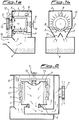
- the figure 1.a shows a filter 15 for motorized sweepers, according to a preferred embodiment of the invention, seen in side section.
- the filtering element 1 comprises a surface of material apt to absorb the dust, folded like an accordion and substantially cylindrical in shape.
- the element 1 could be set in rotation by a motor 8, around a substantially horizontal axis, with the aid of supporting rollers 5.
- the element 1 is contained inside a upper low pressure chamber 3 set above the lower low pressure chamber 4, suited to the collection of dust; it is furthermore maintained in position by a pivot 10 and could be set in rotation manually if necessary, or removed from the machine, with the aid of the handle 9.
- an external aspirator 2 On a side of the chamber 3 is arranged an external aspirator 2 and above this is fitted a low pressure sensor 12.
- Figure 1.a also shows a rigid comb 7 and the sealing gaskets 6 of the filtering element.
- Figure 1.b shows the filter 15 in frontal section, demonstrating the presence of one or more combs 7, of support rollers 5 and of a separator wall 11.
- the fan 2 is in operation and sucks in air which enters the lower chamber 4 through a nozzle 16. In the larger part of the chamber 4 the speed of the air is reduced and the heavy particles contained in it are deposited on the bottom, while the light parts are retained by the filter. Finally the air exits through the fan 2. (The course followed by the air in the various embodiments of the present invention is shown by the arrows in the figures 1.a, 1.b, 2 and 3).
- the fan 2 When it is necessary to clean the filter, the fan 2 is stopped, or the flow of aspiration is diverted and the filtering element 1 is set in rotation by the motor 8, or alternatively, manually using the handle 9. While the filtering element 1 rotates, the fins knock against the combs 7 and vibrate in such a way that the dust on them is flicked off and is deposited on the bottom of the chamber 4.
- the motor 8 can also be set in rotation automatically by means of the low-pressure sensor 12 which removes any possible clogging of the filter. Also in this case, during the rotation of the element 1, the fan 2 is stopped or the flow of aspiration is diverted. Furthermore, it is possible to provide a device to interrupt the relative rotation of said filtering element and of said comb in a position mutually different from the initial one, so that the filter is worn uniformly.
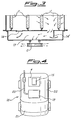
- Figure 2 shows a side view in section of an alternative embodiment of the filter according to the present invention, in which the cylindrical filtering element 1 has substantially vertical axis.
- the element 1 stays in fixed position during the operations of cleaning the filter, while the motor sets in rotation a frame 13 on which are solidly fitted the rigid or semirigid combs 7.
- the combs 7 knock against the fins of the element 1 and they provoke the separation of the dust retained in them.
- the rotation of the frame 13 can also be effected manually by means of the handle 9, which can also be used for the removal of the frame 13 and of the element 1.
- An alternative embodiment of the present invention provides for the employment of two or more filters in parallel, each endowed with its own low-pressure chamber and with its own fan. Naturally, when the cleaning of a filter is proceeded to, the aspiration of the corresponding fan is excluded.
- Figure 3 shows a partial view from the top in section of a further embodiment of the filter according to the present invention, analogous to that just described, comprising two filtering elements 1 and 1' equipped with a common aspirator 2.
- the shutter 14 is set in the closed position shown in figure 3, and the element 1 is set in rotation automatically and cleaned following the procedures previously described, while the fan 2 remains operating and the element 1' continues its filtering action since the shutter 14' stays open.
- Figure 4 shows a schematic view from the top of a motorized sweeper 18 equipped with a motor 19 and the related trunking 20 for the exhaust gases; provision is also made for a filter 15 according to the invention.
- the system of cleaning previously described allows maintenance of a high level of efficiency of the filter 15 over the course of time, thus making it possible to fit a filter 15 of reduced dimensions on the machine 18.
- the reduced area of the filter 15 and of its low-pressure chamber 4, allows a corresponding reduction in the dimensions of the motorized sweeper 18.
- the motorized sweeper 18 it is possible to lodge said motor 19 and said filter 15 inside a single bay 22.
- the filter 15 it is possible to arrange the filter 15 on the outside of the aforesaid bay, in as much as it has its own independent chamber which could be connected with the aspirator and the dust unloaded by means of suitable conduits.
- Both these solutions allow more space to house the motor 19 and its own cooling needs and they offer the possibility of positioning the motor 19 farther from the driving position 21 of the motorized sweeper 18, with consequent benefits in terms of reduced noise and increased driving comfort.
- the reduced dimensions of the filter finally allow a corridor for the disposal of the hot air from the motor, whose outflow is favoured also by the free spaces inside the filtering system.
- the air is therefore introduced into the environment at a lower temperature and in a farther position from the driver.
- the terminal part of the body of the vehicle has the form substantially of a truncated-cone, with the larger part disposed in correspondence of the rear part of the machine.
Landscapes
- Chemical & Material Sciences (AREA)
- Chemical Kinetics & Catalysis (AREA)
- Engineering & Computer Science (AREA)
- Mechanical Engineering (AREA)
- Architecture (AREA)
- Civil Engineering (AREA)
- Structural Engineering (AREA)
- Physics & Mathematics (AREA)
- Geometry (AREA)
- Filtering Of Dispersed Particles In Gases (AREA)
- Control Of Electric Motors In General (AREA)
Abstract
Description
- The present invention relates to a filter for motorized sweepers, as well as to a machine with improved characteristics derived from the employment of the aforesaid filter. The motorized sweepers are used, for instance, for the cleaning of the road mantle, of the flooring in public buildings, factories, railways stations, etc.
- These machines generally comprise one or more rotating elements in contact with the ground, a system of dust aspiration, a filtration system and a chamber to collect the dust.
- Various types of filters for motorized sweepers are known in the art. A first type of filter consists of one or more panels of paper which are folded like an accordion to increase the filtering surface. A second type consists of bags containing filter material, and a third type comprises vertically disposed cylindrical cartridges inside of which is arranged an accordion-folded filtering element.
- A first problem of the known filters is their excessive encumbrance. This results in the present motorized sweepers necessarily comprising a large bay to house the filter. This bay occupies a large part of the volume of the machine, and almost completely separates the front part from the back part of the machine, in a such a way as to make it difficult to arrange other components and, in particular, the trunking for the exhaust gases produced by the motor. Furthermore, this results in the motor being necessarily lodged in a bay of reduced dimensions, behind the driving place with consequent heating and noise problems.
- A second problem is cleaning the filter efficiently. Cleaning is effected by jolting the same filter by hand or by machine. For instance, in the case of the vertical cylindrical cartridges filter a system is used that involves striking repeatedly the cartridge with a hammer or vibrator. This method presents however the problem that the dirt tends to stay in the lower parts of the filter, causing a reduction of efficiency of up to 2/3 in a short time.
- A further system is known for cleaning a panel filter for motorized sweeper by hand, using one or more combs attached to a frame, which are manually run along the surface of the panel.
- The purpose of the present invention is to resolve the aforementioned problems by means of a filter for motorized sweepers that is of limited encumbrance and is easy to clean.
- A further purpose of the present invention is to produce a motorized sweeper equipped with the aforesaid filter which would be less polluting, quieter, and more comfortable for the operator to use.
- Such purpose is achieved by the present invention, which relates to a filter for motorized sweepers comprising a filter element, substantially cylindrical in shape and folded like an accordion to form a multiplicity of fins, an aspirator and a low pressure chamber to store the dust collected, characterized by providing a motor that sets said fins of said filtering element in relative movement with respect to at least one striker or a rigid or semirigid comb interfering with the fins, to effect the separation of the dust from the said filtering element through the flexing and elastic return to position of the same fins.
- According to a preferred embodiment of the present invention, the said filtering element has its axis of rotation in a substantially horizontal position and is set in rotation by the said motor so that the fins of the filtering element knock against at least one fixed rigid or semirigid comb. In the cleaning phase, the said fins of the filtering element present themselves divergent and turned toward the refuse container, facilitating in this way the separation and collection of the dust.
- The present invention relates further to a motorized sweeper equipped with a filter according to any of the preceding claims, characterized by providing at least one corridor, terminating at the rear with respect to the driving position, for the disposal of the hot gases produced by the motor.
- The invention presents different advantages compared to the present state of the art. Above all, knocking the fins of the filtering element against the combs allows the dust to be shaken from the same filter in a more efficient way compared to the known technique, with total elimination of the dust and without risk of partial clogging of the filter. That allows, as a consequence, the production of a filter with less encumbrance and, therefore, the production a motorized sweeper of smaller dimensions, and the endowment of the said machine of at least one corridor for disposal of the hot air produced by the motor, which vents in a position to the rear of the driving position or, in any case, far from it, making the vehicle more comfortable and silent; that further allows the provision of more space for the motor reducing the problems of overheating. Furthermore, the hot gases are released into the environment at a lower temperature and farther from the driving position, in a direction opposite to that of advancement of the machine, thus reducing the problems of heat and acoustic pollution.
- The invention will now be described in more detail with reference to the drawings enclosed which are of an illustrative and not limitative nature, in which:
- figures 1.a and 1.b are respectively a side view and a frontal view, in section, of a preferred embodiment of the filter according to the present invention;
- figure 2 is a side view in section of an alternative embodiment of the filter according to the present invention;
- figure 3 is a partial view from the top in section of an another embodiment of a filter according to the invention comprising two elements equipped with filters and a common aspirator, and
- figure 4 is a schematic view from the top of a motorized sweeper using the filter according to the present invention.
- The figure 1.a shows a
filter 15 for motorized sweepers, according to a preferred embodiment of the invention, seen in side section. The filtering element 1 comprises a surface of material apt to absorb the dust, folded like an accordion and substantially cylindrical in shape. The element 1 could be set in rotation by a motor 8, around a substantially horizontal axis, with the aid of supportingrollers 5. The element 1 is contained inside a upper low pressure chamber 3 set above the lower low pressure chamber 4, suited to the collection of dust; it is furthermore maintained in position by apivot 10 and could be set in rotation manually if necessary, or removed from the machine, with the aid of the handle 9. On a side of the chamber 3 is arranged an external aspirator 2 and above this is fitted alow pressure sensor 12. Figure 1.a also shows arigid comb 7 and the sealing gaskets 6 of the filtering element. - Figure 1.b shows the
filter 15 in frontal section, demonstrating the presence of one ormore combs 7, ofsupport rollers 5 and of aseparator wall 11. - During normal operation of the motorized sweeper, the fan 2 is in operation and sucks in air which enters the lower chamber 4 through a
nozzle 16. In the larger part of the chamber 4 the speed of the air is reduced and the heavy particles contained in it are deposited on the bottom, while the light parts are retained by the filter. Finally the air exits through the fan 2. (The course followed by the air in the various embodiments of the present invention is shown by the arrows in the figures 1.a, 1.b, 2 and 3). - When it is necessary to clean the filter, the fan 2 is stopped, or the flow of aspiration is diverted and the filtering element 1 is set in rotation by the motor 8, or alternatively, manually using the handle 9. While the filtering element 1 rotates, the fins knock against the
combs 7 and vibrate in such a way that the dust on them is flicked off and is deposited on the bottom of the chamber 4. The motor 8 can also be set in rotation automatically by means of the low-pressure sensor 12 which removes any possible clogging of the filter. Also in this case, during the rotation of the element 1, the fan 2 is stopped or the flow of aspiration is diverted. Furthermore, it is possible to provide a device to interrupt the relative rotation of said filtering element and of said comb in a position mutually different from the initial one, so that the filter is worn uniformly. - It is moreover possible to set in rotation the filtering element 1 at pre-set intervals of time while the machine is operating, actuating the motor 8 by means of a timer (not shown). The rotation of the filtering element 1 is then stopped after it has made a suitable number of fractions of rotation, expecially to arrive at a final position different to the initial one.
- The cleaning of the filter, after the end of the utilization of the motorized sweeper, is then made by means of the motor 8, or manually, with the handle 9.
- Figure 2 shows a side view in section of an alternative embodiment of the filter according to the present invention, in which the cylindrical filtering element 1 has substantially vertical axis. Opposite to the embodiment previously described, the element 1 stays in fixed position during the operations of cleaning the filter, while the motor sets in rotation a
frame 13 on which are solidly fitted the rigid orsemirigid combs 7. Thecombs 7 knock against the fins of the element 1 and they provoke the separation of the dust retained in them. The rotation of theframe 13 can also be effected manually by means of the handle 9, which can also be used for the removal of theframe 13 and of the element 1. - An alternative embodiment of the present invention (not shown) provides for the employment of two or more filters in parallel, each endowed with its own low-pressure chamber and with its own fan. Naturally, when the cleaning of a filter is proceeded to, the aspiration of the corresponding fan is excluded.
- Figure 3 shows a partial view from the top in section of a further embodiment of the filter according to the present invention, analogous to that just described, comprising two filtering elements 1 and 1' equipped with a common aspirator 2. In this case there is only one
chamber 17 which allows the fluid communication between the elements 1 and 1' and there areshutters 14 and 14' that serve to isolate alternatively one of the two filtering elements 1 and 1', from the flow of inhaled air. Wherever for instance, it is necessary to clean the element 1, theshutter 14 is set in the closed position shown in figure 3, and the element 1 is set in rotation automatically and cleaned following the procedures previously described, while the fan 2 remains operating and the element 1' continues its filtering action since the shutter 14' stays open. - In the aforementioned cases in which two (or more) filtering elements in parallel are present, it is possible, with the aim of automatically clean the filtering elements during the utilization of the motorized sweeper, to set in rotation at pre-set intervals of time one of the filtering elements, by means of a starting signal from a timer, while at the same time the corresponding fan is stopped (or, as in the case of figure 3, while the shutter, corresponding to the filtering element which is set in motion, is closed). During the aforementioned cleaning operations relative to one of the filtering elements, the other element (or possibly the others, if present) continues to perform its filtering action.
- Figure 4 shows a schematic view from the top of a motorized
sweeper 18 equipped with amotor 19 and therelated trunking 20 for the exhaust gases; provision is also made for afilter 15 according to the invention. The system of cleaning previously described allows maintenance of a high level of efficiency of thefilter 15 over the course of time, thus making it possible to fit afilter 15 of reduced dimensions on themachine 18. The reduced area of thefilter 15 and of its low-pressure chamber 4, allows a corresponding reduction in the dimensions of themotorized sweeper 18. - Furthermore, in the motorized
sweeper 18 according to the invention it is possible to lodge saidmotor 19 and saidfilter 15 inside asingle bay 22. Alternatively, it is possible to arrange thefilter 15 on the outside of the aforesaid bay, in as much as it has its own independent chamber which could be connected with the aspirator and the dust unloaded by means of suitable conduits. Both these solutions allow more space to house themotor 19 and its own cooling needs and they offer the possibility of positioning themotor 19 farther from the drivingposition 21 of themotorized sweeper 18, with consequent benefits in terms of reduced noise and increased driving comfort. The reduced dimensions of the filter finally allow a corridor for the disposal of the hot air from the motor, whose outflow is favoured also by the free spaces inside the filtering system. The air is therefore introduced into the environment at a lower temperature and in a farther position from the driver. To favor further the aforesaid rear outflow of the air, in a direction opposite to that of the progress of the vehicle, it is provided that the terminal part of the body of the vehicle has the form substantially of a truncated-cone, with the larger part disposed in correspondence of the rear part of the machine.
Claims (12)
- Filter for motorized sweepers comprising a filtering element, substantially cylindrical in shape and folded like an accordion to form a multiplicity of fins, an aspirator and a low-pressure chamber for the collection of dust, characterized by providing a motor that sets said fins of said filtering element in relative movement with respect to at least one striker or a rigid or semirigid comb which interfere with the fins, to effect the separation of the dust from said filtering element through flexing and elastic return to position of the same fins.
- Filter according to claim 1, characterized by said filtering element having an axis of rotation in a substantially horizontal position and being set in rotation by the said motor so that the fins of the filtering element knock against at least one rigid or semirigid fixed comb.
- Filter according to claim 2, characterized by said filtering element being connected to a handle that enables manual rotation and extraction from the machine.
- Filter according to claim 1, characterized by said cylindrical filtering element having an axis substantially vertical and being in fixed position while said motor sets in rotation a frame on which are fitted solidly at least two rigid or semirigid combs.
- Filter according to claim 4, characterized by said available frame in rotation being connected to a handle for manual rotation and the extraction of the group composed of said frame and said cylindrical filtering element.
- Filter according to any of the preceding claims, characterized by comprising two filtering elements arranged in parallel and being equipped with a common aspirator and with a means of alternatively isolating from the aspired air flow one of the two filtering elements
- Filter according to any of the preceding claims, characterized by comprising a low-pressure sensor to furnish a starting signal to said motor and a simultaneous stop signal of the flow of air for said aspirator.
- Filter according to claims 1, 2, 3, 6 o 7, characterized by providing a device to interrupt the relative rotation of said filtering element and said comb in a final position mutually different from the initial one.
- Filter according to claim 8, characterized by comprising a timer to send a starting signal to said motor during the filtering operation for a pre-set number of fractions of rotation.
- Motorized sweeper equipped with a filter according to any of the preceding claims, characterized by providing at least one corridor, terminating to the rear with respect to driving position, for the disposal of the hot air produced by the motor.
- Motorized sweeper according to claim 9, characterized by lodging said motor and said filter inside a single bay.
- Motorized sweeper according to claim 9, characterized by lodging said filter outside of said bay.
Priority Applications (1)
| Application Number | Priority Date | Filing Date | Title |
|---|---|---|---|
| DK97103007T DK0793988T3 (en) | 1996-03-06 | 1997-02-25 | Filter for a motorized sweeper and related machine |
Applications Claiming Priority (2)
| Application Number | Priority Date | Filing Date | Title |
|---|---|---|---|
| ITMI960430 | 1996-03-06 | ||
| IT96MI000430A IT1283193B1 (en) | 1996-03-06 | 1996-03-06 | FILTER FOR MOTOR SWEEPER MACHINE |
Publications (3)
| Publication Number | Publication Date |
|---|---|
| EP0793988A2 true EP0793988A2 (en) | 1997-09-10 |
| EP0793988A3 EP0793988A3 (en) | 1997-09-17 |
| EP0793988B1 EP0793988B1 (en) | 2004-09-15 |
Family
ID=11373511
Family Applications (1)
| Application Number | Title | Priority Date | Filing Date |
|---|---|---|---|
| EP97103007A Expired - Lifetime EP0793988B1 (en) | 1996-03-06 | 1997-02-25 | Motorized sweeper |
Country Status (3)
| Country | Link |
|---|---|
| EP (1) | EP0793988B1 (en) |
| DK (1) | DK0793988T3 (en) |
| IT (1) | IT1283193B1 (en) |
Cited By (13)
| Publication number | Priority date | Publication date | Assignee | Title |
|---|---|---|---|---|
| DE19851666C1 (en) * | 1998-11-10 | 2000-09-21 | Wap Reinigungssysteme | Ride-on sweeper with front engine |
| EP1122365A3 (en) * | 2000-02-01 | 2003-02-05 | Tennant Company | Filter system for mobile debris collection machine |
| EP1535564A2 (en) | 2003-11-28 | 2005-06-01 | Alfred Kärcher GmbH & Co. KG | Floor cleaning machine |
| EP1707679A1 (en) * | 2005-03-01 | 2006-10-04 | Eureka S.R.L. | Manually-operated sweeper |
| WO2007016754A3 (en) * | 2005-08-09 | 2007-03-29 | Green Liiiie 2000 Bv Met Beper | Device for cleaning streets, squares, fields and the like. |
| FR2953734A1 (en) * | 2009-12-15 | 2011-06-17 | Renault Sas | RECYCLABLE PARTICLE FILTER |
| JP2013506568A (en) * | 2009-10-02 | 2013-02-28 | ジェイピーエル グローバル,エルエルシー | Power saw device with integrated dust collector |
| BE1024942B1 (en) * | 2016-11-24 | 2018-08-28 | Lange Christian Sa | ROAD SWEEPER |
| KR20200019203A (en) * | 2017-06-20 | 2020-02-21 | 제이피엘 글로벌, 엘엘씨 | Rotatable filter system and method |
| CN111042036A (en) * | 2019-12-20 | 2020-04-21 | 上海高仙自动化科技发展有限公司 | Dust removal box and cleaning robot with same |
| CN112554113A (en) * | 2020-12-04 | 2021-03-26 | 安徽南博机器人有限公司 | Electric road sweeper |
| CN112575722A (en) * | 2020-12-04 | 2021-03-30 | 安徽南博机器人有限公司 | High-efficient filter equipment of road sweeper dust |
| CN115041386A (en) * | 2022-05-25 | 2022-09-13 | 马彩荣 | Quick dust collecting equipment of wisdom agricultural seed |
Families Citing this family (2)
| Publication number | Priority date | Publication date | Assignee | Title |
|---|---|---|---|---|
| WO2022057641A1 (en) * | 2020-09-17 | 2022-03-24 | 广东博智林机器人有限公司 | Floor cleaning device |
| CN113877312A (en) * | 2021-10-07 | 2022-01-04 | 周常生 | Air filtering device for preventing and treating environmental pollution |
Family Cites Families (2)
| Publication number | Priority date | Publication date | Assignee | Title |
|---|---|---|---|---|
| US3898414A (en) * | 1974-05-06 | 1975-08-05 | Dollinger Corp | Filter unit with cleaning attachment |
| SE451947B (en) * | 1984-05-30 | 1987-11-09 | Nederman Philip & Co Ab | Filter cleaning device |
-
1996
- 1996-03-06 IT IT96MI000430A patent/IT1283193B1/en active IP Right Grant
-
1997
- 1997-02-25 EP EP97103007A patent/EP0793988B1/en not_active Expired - Lifetime
- 1997-02-25 DK DK97103007T patent/DK0793988T3/en active
Cited By (22)
| Publication number | Priority date | Publication date | Assignee | Title |
|---|---|---|---|---|
| DE19851666C1 (en) * | 1998-11-10 | 2000-09-21 | Wap Reinigungssysteme | Ride-on sweeper with front engine |
| EP1122365A3 (en) * | 2000-02-01 | 2003-02-05 | Tennant Company | Filter system for mobile debris collection machine |
| EP1535564A2 (en) | 2003-11-28 | 2005-06-01 | Alfred Kärcher GmbH & Co. KG | Floor cleaning machine |
| DE10356419B3 (en) * | 2003-11-28 | 2005-06-02 | Alfred Kärcher Gmbh & Co. Kg | Floor cleaning machine |
| EP1535564A3 (en) * | 2003-11-28 | 2008-04-09 | Alfred Kärcher GmbH & Co. KG | Floor cleaning machine |
| EP1707679A1 (en) * | 2005-03-01 | 2006-10-04 | Eureka S.R.L. | Manually-operated sweeper |
| WO2007016754A3 (en) * | 2005-08-09 | 2007-03-29 | Green Liiiie 2000 Bv Met Beper | Device for cleaning streets, squares, fields and the like. |
| US9221110B2 (en) | 2009-10-02 | 2015-12-29 | JPL Global, LLC | Power saw apparatus with integrated dust collector |
| JP2013506568A (en) * | 2009-10-02 | 2013-02-28 | ジェイピーエル グローバル,エルエルシー | Power saw device with integrated dust collector |
| WO2011080430A1 (en) * | 2009-12-15 | 2011-07-07 | Renault S.A.S. | Recyclable particle filter |
| FR2953734A1 (en) * | 2009-12-15 | 2011-06-17 | Renault Sas | RECYCLABLE PARTICLE FILTER |
| BE1024942B1 (en) * | 2016-11-24 | 2018-08-28 | Lange Christian Sa | ROAD SWEEPER |
| EP3641911A4 (en) * | 2017-06-20 | 2021-01-20 | JPL Global, LLC | ROTARY FILTER SYSTEM AND METHODOLOGY |
| KR20200019203A (en) * | 2017-06-20 | 2020-02-21 | 제이피엘 글로벌, 엘엘씨 | Rotatable filter system and method |
| AU2018288842B2 (en) * | 2017-06-20 | 2023-12-14 | JPL Global, LLC | Rotatable filter system and methodology |
| KR102616396B1 (en) | 2017-06-20 | 2023-12-27 | 제이피엘 글로벌, 엘엘씨 | Rotatable filter system and method |
| AU2024201428B2 (en) * | 2017-06-20 | 2026-04-09 | JPL Global, LLC | Rotatable filter system and methodology |
| CN111042036A (en) * | 2019-12-20 | 2020-04-21 | 上海高仙自动化科技发展有限公司 | Dust removal box and cleaning robot with same |
| CN112554113A (en) * | 2020-12-04 | 2021-03-26 | 安徽南博机器人有限公司 | Electric road sweeper |
| CN112575722A (en) * | 2020-12-04 | 2021-03-30 | 安徽南博机器人有限公司 | High-efficient filter equipment of road sweeper dust |
| CN115041386A (en) * | 2022-05-25 | 2022-09-13 | 马彩荣 | Quick dust collecting equipment of wisdom agricultural seed |
| CN115041386B (en) * | 2022-05-25 | 2024-04-12 | 新疆金天山农业科技有限责任公司 | A smart agricultural seed rapid dust removal device |
Also Published As
| Publication number | Publication date |
|---|---|
| DK0793988T3 (en) | 2005-01-10 |
| IT1283193B1 (en) | 1998-04-16 |
| ITMI960430A0 (en) | 1996-03-06 |
| EP0793988B1 (en) | 2004-09-15 |
| EP0793988A3 (en) | 1997-09-17 |
| ITMI960430A1 (en) | 1997-09-06 |
Similar Documents
| Publication | Publication Date | Title |
|---|---|---|
| EP0793988A2 (en) | Filter for a motorized sweeper and related machine | |
| CN106196325B (en) | Mobile indoor environment cleaning robot | |
| US5013333A (en) | Unattended air cleaning system for surface maintenance machine | |
| US6598263B2 (en) | Vacuum cleaner dirt collecting system with filter cleaning devices | |
| EP0793438B1 (en) | A vacuum cleaner and a filter assembly therefor | |
| US20070000221A1 (en) | Air purifier | |
| JP2007038215A (en) | Air conditioner | |
| CN117482655B (en) | Dust collector is used in base cloth processing | |
| GB2270334A (en) | Pneumatic refuse collection and filter apparatus for a roadsweeper | |
| CN216409200U (en) | Air pipe with air purification function for heating ventilation air conditioner | |
| CN211476162U (en) | Air purification device for workshop | |
| JP2005279503A (en) | Filter unit and electric vacuum cleaner using the filter unit | |
| CN214682286U (en) | Diversified electrostatic precipitator device that shakes | |
| KR100496163B1 (en) | A dust collector, and vacuum cleaner using the same | |
| KR200376989Y1 (en) | Collector of a Mini-Cleaning Car | |
| CN109323327A (en) | Air conditioner indoor unit and control method | |
| JP3632370B2 (en) | Filter dust remover for floor cleaning vehicles | |
| CN215650893U (en) | Cleaning robot | |
| JPH0713449U (en) | air purifier | |
| JPH04341314A (en) | High speed dust collector | |
| CN215785581U (en) | Intelligent ventilation controller for laboratory | |
| JPH11300233A (en) | Electrostatic dust collector | |
| CN216320615U (en) | Intelligent controller for pulse bag type dust collector | |
| JP2000042333A (en) | Air cleaner | |
| JPS6157217A (en) | Filtering type dust collector |
Legal Events
| Date | Code | Title | Description |
|---|---|---|---|
| PUAI | Public reference made under article 153(3) epc to a published international application that has entered the european phase |
Free format text: ORIGINAL CODE: 0009012 |
|
| PUAL | Search report despatched |
Free format text: ORIGINAL CODE: 0009013 |
|
| AK | Designated contracting states |
Kind code of ref document: A2 Designated state(s): CH DK FR GB LI |
|
| AK | Designated contracting states |
Kind code of ref document: A3 Designated state(s): CH DK FR GB LI |
|
| 17P | Request for examination filed |
Effective date: 19980312 |
|
| RAP3 | Party data changed (applicant data changed or rights of an application transferred) |
Owner name: GANSOW ELEKTROBAU GMBH |
|
| 17Q | First examination report despatched |
Effective date: 20010629 |
|
| GRAP | Despatch of communication of intention to grant a patent |
Free format text: ORIGINAL CODE: EPIDOSNIGR1 |
|
| RTI1 | Title (correction) |
Free format text: MOTORIZED SWEEPER |
|
| GRAS | Grant fee paid |
Free format text: ORIGINAL CODE: EPIDOSNIGR3 |
|
| RAP1 | Party data changed (applicant data changed or rights of an application transferred) |
Owner name: INTERPUMP CLEANING S.P.A. |
|
| GRAA | (expected) grant |
Free format text: ORIGINAL CODE: 0009210 |
|
| AK | Designated contracting states |
Kind code of ref document: B1 Designated state(s): CH DK FR GB LI |
|
| REG | Reference to a national code |
Ref country code: GB Ref legal event code: FG4D Ref country code: CH Ref legal event code: EP |
|
| REG | Reference to a national code |
Ref country code: CH Ref legal event code: NV Representative=s name: WILLIAM BLANC & CIE CONSEILS EN PROPRIETE INDUSTRI |
|
| PGFP | Annual fee paid to national office [announced via postgrant information from national office to epo] |
Ref country code: GB Payment date: 20050217 Year of fee payment: 9 |
|
| PGFP | Annual fee paid to national office [announced via postgrant information from national office to epo] |
Ref country code: FR Payment date: 20050225 Year of fee payment: 9 |
|
| PGFP | Annual fee paid to national office [announced via postgrant information from national office to epo] |
Ref country code: DK Payment date: 20050228 Year of fee payment: 9 |
|
| PGFP | Annual fee paid to national office [announced via postgrant information from national office to epo] |
Ref country code: CH Payment date: 20050301 Year of fee payment: 9 |
|
| PLBE | No opposition filed within time limit |
Free format text: ORIGINAL CODE: 0009261 |
|
| STAA | Information on the status of an ep patent application or granted ep patent |
Free format text: STATUS: NO OPPOSITION FILED WITHIN TIME LIMIT |
|
| ET | Fr: translation filed | ||
| 26N | No opposition filed |
Effective date: 20050616 |
|
| PG25 | Lapsed in a contracting state [announced via postgrant information from national office to epo] |
Ref country code: GB Free format text: LAPSE BECAUSE OF NON-PAYMENT OF DUE FEES Effective date: 20060225 |
|
| PG25 | Lapsed in a contracting state [announced via postgrant information from national office to epo] |
Ref country code: LI Free format text: LAPSE BECAUSE OF NON-PAYMENT OF DUE FEES Effective date: 20060228 Ref country code: DK Free format text: LAPSE BECAUSE OF NON-PAYMENT OF DUE FEES Effective date: 20060228 Ref country code: CH Free format text: LAPSE BECAUSE OF NON-PAYMENT OF DUE FEES Effective date: 20060228 |
|
| REG | Reference to a national code |
Ref country code: DK Ref legal event code: EBP |
|
| REG | Reference to a national code |
Ref country code: CH Ref legal event code: PL |
|
| GBPC | Gb: european patent ceased through non-payment of renewal fee |
Effective date: 20060225 |
|
| REG | Reference to a national code |
Ref country code: FR Ref legal event code: ST Effective date: 20061031 |
|
| PG25 | Lapsed in a contracting state [announced via postgrant information from national office to epo] |
Ref country code: FR Free format text: LAPSE BECAUSE OF NON-PAYMENT OF DUE FEES Effective date: 20060228 |