EP0793369B1 - Method for automatically obtaining, in closed form, the coefficients of an equalizing network in a system of data transmission of Orthogonal Frequency Division Multiplexing (OFDM) type - Google Patents
Method for automatically obtaining, in closed form, the coefficients of an equalizing network in a system of data transmission of Orthogonal Frequency Division Multiplexing (OFDM) type Download PDFInfo
- Publication number
- EP0793369B1 EP0793369B1 EP96117528A EP96117528A EP0793369B1 EP 0793369 B1 EP0793369 B1 EP 0793369B1 EP 96117528 A EP96117528 A EP 96117528A EP 96117528 A EP96117528 A EP 96117528A EP 0793369 B1 EP0793369 B1 EP 0793369B1
- Authority
- EP
- European Patent Office
- Prior art keywords
- coefficients
- ofdm
- transmission
- data
- reception side
- Prior art date
- Legal status (The legal status is an assumption and is not a legal conclusion. Google has not performed a legal analysis and makes no representation as to the accuracy of the status listed.)
- Expired - Lifetime
Links
Images


Classifications
-
- H—ELECTRICITY
- H04—ELECTRIC COMMUNICATION TECHNIQUE
- H04L—TRANSMISSION OF DIGITAL INFORMATION, e.g. TELEGRAPHIC COMMUNICATION
- H04L25/00—Baseband systems
- H04L25/02—Details ; arrangements for supplying electrical power along data transmission lines
- H04L25/03—Shaping networks in transmitter or receiver, e.g. adaptive shaping networks
- H04L25/03006—Arrangements for removing intersymbol interference
- H04L25/03012—Arrangements for removing intersymbol interference operating in the time domain
- H04L25/03114—Arrangements for removing intersymbol interference operating in the time domain non-adaptive, i.e. not adjustable, manually adjustable, or adjustable only during the reception of special signals
- H04L25/03146—Arrangements for removing intersymbol interference operating in the time domain non-adaptive, i.e. not adjustable, manually adjustable, or adjustable only during the reception of special signals with a recursive structure
-
- H—ELECTRICITY
- H04—ELECTRIC COMMUNICATION TECHNIQUE
- H04L—TRANSMISSION OF DIGITAL INFORMATION, e.g. TELEGRAPHIC COMMUNICATION
- H04L27/00—Modulated-carrier systems
- H04L27/26—Systems using multi-frequency codes
- H04L27/2601—Multicarrier modulation systems
- H04L27/2647—Arrangements specific to the receiver only
-
- H—ELECTRICITY
- H04—ELECTRIC COMMUNICATION TECHNIQUE
- H04L—TRANSMISSION OF DIGITAL INFORMATION, e.g. TELEGRAPHIC COMMUNICATION
- H04L25/00—Baseband systems
- H04L25/02—Details ; arrangements for supplying electrical power along data transmission lines
- H04L25/03—Shaping networks in transmitter or receiver, e.g. adaptive shaping networks
- H04L25/03006—Arrangements for removing intersymbol interference
- H04L2025/0335—Arrangements for removing intersymbol interference characterised by the type of transmission
- H04L2025/03375—Passband transmission
- H04L2025/03414—Multicarrier
-
- H—ELECTRICITY
- H04—ELECTRIC COMMUNICATION TECHNIQUE
- H04L—TRANSMISSION OF DIGITAL INFORMATION, e.g. TELEGRAPHIC COMMUNICATION
- H04L25/00—Baseband systems
- H04L25/02—Details ; arrangements for supplying electrical power along data transmission lines
- H04L25/03—Shaping networks in transmitter or receiver, e.g. adaptive shaping networks
- H04L25/03006—Arrangements for removing intersymbol interference
- H04L2025/03592—Adaptation methods
- H04L2025/03745—Timing of adaptation
- H04L2025/03764—Timing of adaptation only during predefined intervals
- H04L2025/0377—Timing of adaptation only during predefined intervals during the reception of training signals
-
- H—ELECTRICITY
- H04—ELECTRIC COMMUNICATION TECHNIQUE
- H04L—TRANSMISSION OF DIGITAL INFORMATION, e.g. TELEGRAPHIC COMMUNICATION
- H04L25/00—Baseband systems
- H04L25/02—Details ; arrangements for supplying electrical power along data transmission lines
- H04L25/03—Shaping networks in transmitter or receiver, e.g. adaptive shaping networks
- H04L25/03006—Arrangements for removing intersymbol interference
- H04L2025/03777—Arrangements for removing intersymbol interference characterised by the signalling
- H04L2025/03783—Details of reference signals
Definitions
- the present invention refers to a method for the calculation of the interference coefficients in a data transmission system of the OFDM (Orthogonal Frequency Division Multiplexing) type with only the knowledge of the pulse response of the transmission channel.
- OFDM Orthogonal Frequency Division Multiplexing
- QAM Quadrature Amplitude Modulation
- the signal, passing through the transmission channel is distorted and each symbol is affected by an interference, generally due both to the symbols of the same block, and to the symbols of the preceding blocks.
- equalisers of the DFE (Decision Feedback Equaliser) type wherein, as known, the interference coefficients are obtained using adaptive, very complicated and expensive methods.
- Aim of the present invention is to indicate a method for determining the interference coefficients, which only needs the knowledge of the pulse response of the channel and allows to obtain equalisers showing very simple and cheap structures.
- the present invention has as its subject a method for determining the interference coefficients showing the features which are indicated in the first claim.
- the band occupation is therefore N times that of the transmission data pulse G T (f), and as the latter in praxis is equal to S times ⁇ f, where S equal to a few units, it is possible to maintain the band of x (t) within a value which is equal to N ⁇ f if the first and the last S symbols of the block are null, i.e. if the relevant carriers are suppressed.
- the said samples are substantially given by the IDFT of the sequence (c o ....C N-1 ) periodic with period N.
- each sample of x (t) is represented by a term of the sequence multiplied by the corresponding sample of the transmission data pulse (taken with alternation of the sign, which represents a frequency translation of N ⁇ f/2, necessary for centring the spectrum around the origin) and is different from zero in the index interval from S to N-S.
- a generic transmitted symbol can be obtained from the DFT of the sequence of duration N, which in turn is obtained substantially adding samples of the received signal, alternately with changed sign, and multiplied by the corresponding samples of g R (t).
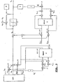
- figure 1 it is represented the synthesis of the transmitter and the receiver according to the 5) and 6).
- the symbols of a block may at the most trespass into the next block mixing with the symbols of the latter.
- the said equaliser shows a "feedforward" part (left side) which defines the h(m,k) coefficients in order to minimise the ICI and a “feedback” part (right side) wherein the h'(m,k) coefficients are calculated in order to minimise the ISI.
- the D block represents the decisional element which assigns to each estimated symbol c k the nearest position c k in the constellation.
- the expression 13) is important because it allows, through the 11) and the 12), to obtain in analytic way (i.e. without an adaptive procedure) the interference coefficients starting only from the knowledge of the pulse response of the channel.
- the latter can be estimated quite easily providing to build up once a data block to be transmitted as a Kronecker pulse and considering the received signal as representing the pulse response of the channel.
- the equaliser structure may be of the type shown in fig. 5, where in a similar way to what has been done in figure 3, only the coefficients relating to the symbols adjacent to the K-th are considered significant, and, for the sake of causality, in the FIR part the received symbols have been considered as an approximation of those equalised. Comparing the diagrams of figures 3) and 5) it appears clear how much the invention is advantageous in terms of simplification and, as a consequence, of cost.
- x n all null but one, are sent, i.e. the channel is tested using the Kronecker function.
- the equaliser's structure can be of the type shown in detail in fig. 5, where, in a similar way to what has been done in figure 3, only the coefficients relating to the symbols adjacent to the k-th are considered significant, and, for the sake of causality, in the FIR part the received symbols have been considered as an approximation of those equalised.
- the method according to the invention allows, in respect of the known methods, a simplification of the necessary apparatuses and therefore a cost reduction, as it is evident comparing figure 3 and figure 5.
Description
- The present invention refers to a method for the calculation of the interference coefficients in a data transmission system of the OFDM (Orthogonal Frequency Division Multiplexing) type with only the knowledge of the pulse response of the transmission channel.
- It is known that a OFDM system transmits a block of data in a finite time T using N subcarriers equally spaced in frequency, on every of them being transmitted a symbol having a duration not greater than T, using a QAM (Quadrature Amplitude Modulation) system and a shaping pulse gT(t), where gT (t)=1 for 0≤t≤T and gT (t)=0 elsewhere.
- The signal, passing through the transmission channel is distorted and each symbol is affected by an interference, generally due both to the symbols of the same block, and to the symbols of the preceding blocks.
- At the reception side, in order to reduce to a minimum the distortion, it is necessary to use equalisers of the DFE (Decision Feedback Equaliser) type wherein, as known, the interference coefficients are obtained using adaptive, very complicated and expensive methods.
- "A description of such methods can be found in document D1 "A comparison between two OFDM modulation systems for digital broadcasting" by Cariolaro et al. ,Proceedings of the International Workshop on HDTV , NL,Amsterdam , Elsevier, Workshop 5, 1994, pp. 279-288.. In the document two OFDM equalized systems are considered, the first one without pulse shaping, and the other with a pulse shaping of the square root raised cosine type with a roll-off factor indicated as a (which corresponds to roll-off factor γ in the patent) . Furthermore two different channel models are examinated: a Ricean fading channel with 40 echoes, a bandwith of 8MHz with a given frequency response N(f); and a second channel of Single Frequency Network type where a longer echo has been added. It can be seen that a very large number of complex multiplications is needed."
- Aim of the present invention is to indicate a method for determining the interference coefficients, which only needs the knowledge of the pulse response of the channel and allows to obtain equalisers showing very simple and cheap structures.
- In order to reach the said aim the present invention has as its subject a method for determining the interference coefficients showing the features which are indicated in the first claim.
- Further characteristics and advantages of the present invention will be clear from the following description and from the attached drawings, which are given only as an indicative and not limiting example.
- In the drawings:
- figure 1 shows the simplified block diagram of an OFDM system without channel distortion;
- figure 2 shows the time behaviours of the pulses of the data in transmission and in reception;
- figure 3 shows the block diagram of a known DFE equaliser;
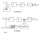
- figure 4 shows the block diagram of the transmitter and of the receiver of data according to the invention;
- figure 5 shows in detail the receiver according to the invention.
- In order to facilitate the reading, in the following the symbols and the terms used are listed.
- Δf
- distance between two subcarriers;
- fP
- R.F. carrier;
- To=1/Δf
- time interval between two subcarriers;
- T
- duration of a data block;
- B=N Δf
- total band of the modulated signal;
- TG=T-To
- guard interval between consecutive blocks;
- gT (t)
- data shaping pulse in transmission of duration T;
- gR (t)
- data shaping pulse in reception of duration To.
- The symbol * used as an index means 'conjugated complex',
used as an operator between two functions means 'convolution'. - Indicating with cn=an+jbn the constellation point associated to the symbol having position n, to each block corresponds the following pulse signal modulated on a carrier frequency fP:

with f'n=fp+fn fn=(n-N/2)Δf - The complex envelope of 1) is given by

wherein:
- In order that the symbols can be recovered at reception side, it is necessary that the family ϕn(t), where n=0,...,N-1, is orthogonal, or, more generally, it is advisable that a family exists Ψk(t), where k=0,...,N-1, so that

(here and in the following two functions indicated with a small letter and the corresponding capital are intended as connected by a Fourier transform) - In the said assumption in fact it results that the value of a symbol received in a position m is given by the interrelation between x(t) and Ψm(t); in fact from the 3) we obtain:

and if:
the preceding orthogonality condition becomes:
- In order to evaluate the band occupied by the complex envelope of the signal of a block, it is necessary to calculate the Fourier transform of the 2):

- The band occupation is therefore N times that of the transmission data pulse GT (f), and as the latter in praxis is equal to S times Δf, where S equal to a few units, it is possible to maintain the band of x(t) within a value which is equal to NΔf if the first and the last S symbols of the block are null, i.e. if the relevant carriers are suppressed. With this assumption, which has been considered valid in the following, we may assume that the total band of x(t) is given by B=NΔf, and therefore x(t) is described by its samples taken at
distances 1/NΔf:
and, with a few calculations, we obtain:
- As can be seen the said samples are substantially given by the IDFT of the sequence (co....CN-1) periodic with period N.
- In particular, each sample of x(t) is represented by a term of the sequence multiplied by the corresponding sample of the transmission data pulse (taken with alternation of the sign, which represents a frequency translation of NΔf/2, necessary for centring the spectrum around the origin) and is different from zero in the index interval from S to N-S.
- Taking in account the Parseval theorem, the 3") and the orthogonality condition, through a few calculations we obtain:

- From the 6) we see that, in case of a channel without transmission distortion, a generic transmitted symbol can be obtained from the DFT of the sequence of duration N, which in turn is obtained substantially adding samples of the received signal, alternately with changed sign, and multiplied by the corresponding samples of gR(t).
- In figure 1 it is represented the synthesis of the transmitter and the receiver according to the 5) and 6). When the x(t) signal passes through a channel having the characteristic of a low-pass filter LP, the output is given by y(t)=x(t)*h(t), wherein h(t) is the pulse response of the filter, which we assume different from zero in the interval (0-Th).
- It is possible to demonstrate that the symbol ck, on the basis of what said before, becomes at the reception side:


and
we obtain
- The 7) proves that in general a transformation LP on x(t) gives at the reception side a cosymbolic interference, i.e. the k-th symbol depends on the symbols of the same block and on their distance from the considered symbol.
- Let's consider the case of a traditional OFDM wherein (see fig. 2) gT(t) and gR(t) show the classic raised cosine behaviour and putting, for the sake of orthogonality,


and, if TG≥ Th, from the previous formulas we obtain
where δ(m)= Kronecker pulse. - From the 8) we see that, if the guard interval TG is greater than the duration Th of the pulse response of the channel, the symbol received in the k position is equal to that transmitted, multiplied by the value of the transfer function in correspondence of the carrier fk, without any cosymbolic interference.
- This result is however no more valid if the duration of the pulse response is longer than the guard interval; assuming e.g. that the pulse response is represented by an echo, delayed by D, where D>TG, we obtain

where a= echo attenuation: and putting

we obtain
- From the 9) we can see that a symbol at a distance m from that interfered shows an interference coefficient which depends on the distance and on the position of the interfering symbol.
- The 7) can be written

where
- In the real case, assuming that the duration of the pulse response is not greater than the duration T of the block, receiving a block we shall only take in account the previous block, as it is clear from fig. 2.
- In fact, if Th<T, the symbols of a block may at the most trespass into the next block mixing with the symbols of the latter.
- If we indicate with [c'n...c'N-1] the sequence of the previous block and with

the relevant complex envelope, we obtain the general expression of the k-th symbol at the reception side
where

- In a similar way to what we see before, the 10) can be written


depending on the symbols of the previous block. - It is possible to demonstrate that

- In order to eliminate the ICI and ISI interferences it is necessary to use at the output of the DFT an equaliser, e.g. of the DFE (Decision Feedback Equaliser) type, which means a quite complicated structure, which is shown in fig. 3, wherein we have assumed η'(0,k)=0, due to the 7').
- The said equaliser shows a "feedforward" part (left side) which defines the h(m,k) coefficients in order to minimise the ICI and a "feedback" part (right side) wherein the h'(m,k) coefficients are calculated in order to minimise the ISI.
- The D block represents the decisional element which assigns to each estimated symbol
c k the nearest position ck in the constellation. - ek=
c k-ck represents the symbol error: Usually after 15-20 blocks a known block is transmitted, whose symbols are memorised in the memory M of the receiver; ek is periodically "refreshed" with real and not with estimated values. - The η coefficients are calculated using the LMS (Least Mean Square) algorithm:


where - µ = adaptation parameter
- t + T indicates the next block to the current block.
- In the fig. 3 there is shown the equalisation of the K-th symbol assuming that the interference is due only to the two adjacent symbols.
- Of course the pattern must be repeated for each of the N symbols so that it is evident the complexity of the known equalisation systems, which must use a high number of adders, multipliers and memories (delays).
- Coming back to the already seen case of a channel whose pulse response shows only one echo (but the results, correctly evaluated, have a general validity) having an attenuation a and a delay D.
- The pulse response is:

and therefore
where
- The calculation of the interference coefficients needs therefore only the knowledge of the ξ(m) coefficients.
- If D≤TG the product gT(t-D) gR(t) is a raised cosine function whose amplitude is 1/TO, whose duration is To and which is centred at TC = TG +TO/2; indicating with GTΔ(f) the Fourier transform of such a function having a duration TΔ and centred at the origin, we obtain: ..

- In the case of D>TG, the said product shows a Fourier transform which cannot be expressed in a simple way in closed form; however, if D≥TG + 2γ To, then the product is still a raised cosine
function having amplitude 1/To, but a duration TΔ = T + 2γTo - D and centred at Tc = (T -2g To+ D) /2; in this case the coefficients ξ(m)
and, more explicitly
- The expression 13) is important because it allows, through the 11) and the 12), to obtain in analytic way (i.e. without an adaptive procedure) the interference coefficients starting only from the knowledge of the pulse response of the channel. The latter can be estimated quite easily providing to build up once a data block to be transmitted as a Kronecker pulse and considering the received signal as representing the pulse response of the channel.
- Knowing the interference coefficients and writing the 10') as follows

the equaliser structure may be of the type shown in fig. 5, where in a similar way to what has been done in figure 3, only the coefficients relating to the symbols adjacent to the K-th are considered significant, and, for the sake of causality, in the FIR part the received symbols have been considered as an approximation of those equalised. Comparing the diagrams of figures 3) and 5) it appears clear how much the invention is advantageous in terms of simplification and, as a consequence, of cost. - For a better understanding of the invention, some further indications are provided.
- The invention can be applied if the following assumptions are met:
- the transmission channel must be linear, i.e.y(t) = x(t)*h(t), where h(t) is the impulse response of the system; it is known that the Fourier transform of h(t) is the transfer function of the channel; the impulse function in the analogue field is the known Dirac function or δ function δ(t); the Kronecker impulse is the equivalent in the digital field δ(n) = 1 for n = 0 and δ(n) = 0 for n ≠ 0.
- the transmission channel must be of the FIR (Finite Impulse Response) type, i.e. the response to the Kronecker impulse must be limited in time (limited number of echoes).
- the distortion of the channel is represented by an echo delayed by D and attenuated by a. Therefore if at the input (transmission side) we have e. g. d(t), at the output (reception side) we have h(t) = d(t) + a d(t-D), or, in digital notation, h(m) = d(m) + a d(m-k).
- Conclusions are valid also in the general case (multiple echoes).
- It is however necessary that D<T in order to limit the considerations to two contiguous blocks.
- The invention starts from equations 11), 12) and 13), wherefore it is clear that the coefficients h and 'h, which up to now are obtained through an adaptive procedure, as in fig. 3, become known, if a and D are known, i.e. attenuation and delay at the reception side.
- Practically we shall proceed as indicated in the block diagram of figure 4:
- Within a determined time interval T (which is periodically repeated, in order to take in account possible variations of the channel response), x n, all null but one, are sent, i.e. the channel is tested using the Kronecker function.
- This can be obtained, for instance, using a block of cn = 1/N so that, from the 5), we obtain x o=1 (not considering the constant) and all other x=0.
- If we want to have x k=1 it must be cn =1/N e-j2πnk/N.
- At the reception side there are present only x k and x k+D, i.e. the impulse and its echo, delayed by D and attenuated by a, where D and a are easily measurable.
- By means of a microprocessor, usually available in the system for executing other functions, formulas 11) 12) and 13) are processed once in order to get the coefficients η(ICI) and η'(ISI). It is no more necessary any special circuitry, as it is clear from fig. 4.
- The equaliser's structure can be of the type shown in detail in fig. 5, where, in a similar way to what has been done in figure 3, only the coefficients relating to the symbols adjacent to the k-th are considered significant, and, for the sake of causality, in the FIR part the received symbols have been considered as an approximation of those equalised.
- We may summarise that, if the distortion of the channel is represented by one or more attenuated echoes, which is the most frequent case, equations 11), 12) and 13), allow to determine the ICI and ISI coefficients having the knowledge of the attenuation and the delay. The quickest way to know them is to transmit a single impulse (Kronecker) and measure the received signal.
- From the above description the characteristics of the method according to the present invention will be clear, as clear are also the advantages thereof.
- In particular the method according to the invention allows, in respect of the known methods, a simplification of the necessary apparatuses and therefore a cost reduction, as it is evident comparing figure 3 and figure 5.
Claims (3)
- Method for obtaining the coefficients of an equalizing network in a data transmission system of Orthogonal Frequency Division Multiplexing type herein after referred to as OFDM with a predetermined guard interval TG, transmitted through a distorting channel having a maximal delay which is longer than said guard interval, in which at the transmission side an impulse signal is sent through the system, characterized by the following steps:- at the reception side the echo of said transmitted impulse signal is detected and the delay D end attenuation a thereof are measured;- the cosymbol interference coefficients η and the intersymbol interference coefficients η' are calculated once, without any adaptive procedure, by means of the formulaswherein


 δ(m) is the Kronecker impulseD is the delay of the echo the reception sidea is the attenuation of the echo at the reception sideγ is the roll-off factor of the data shaping pulses at the transmission side and at the reception side, with a temporal behaviour of the raised cosine type
 fk is the carrier in the k-th position of the OFDM signal.H(fk) is the frequency response of the transmission channel in correspondence of the carrier fkT0 =1/Δf is the duration of the data shaping pulse at the reception sideT is the duration of the data shaping pulse at the transmission sideTG is the guard interval of the OFDM system
 k ,n are indexes that indicate the position of a symbol in the OFDM signalm=k-nΔf is the frequency difference between two adjacent subcarriers.
 - Apparatus for the transmission of data comprising means adapted to perform the method of claim 1.
- Apparatus for the reception of data comprising means adapted to perform the method of claim 1
Applications Claiming Priority (2)
| Application Number | Priority Date | Filing Date | Title |
|---|---|---|---|
| ITTO950889 | 1995-11-03 | ||
| IT95TO000889A IT1281389B1 (en) | 1995-11-03 | 1995-11-03 | METHOD FOR AUTOMATICALLY OBTAINING THE COEFFICIENTS OF AN EQUALIZING NETWORK IN A DATA TRANSMISSION SYSTEM IN CLOSED FORM |
Publications (3)
| Publication Number | Publication Date |
|---|---|
| EP0793369A2 EP0793369A2 (en) | 1997-09-03 |
| EP0793369A3 EP0793369A3 (en) | 2000-05-03 |
| EP0793369B1 true EP0793369B1 (en) | 2007-06-20 |
Family
ID=11413938
Family Applications (1)
| Application Number | Title | Priority Date | Filing Date |
|---|---|---|---|
| EP96117528A Expired - Lifetime EP0793369B1 (en) | 1995-11-03 | 1996-10-31 | Method for automatically obtaining, in closed form, the coefficients of an equalizing network in a system of data transmission of Orthogonal Frequency Division Multiplexing (OFDM) type |
Country Status (5)
| Country | Link |
|---|---|
| EP (1) | EP0793369B1 (en) |
| DE (1) | DE69637138T2 (en) |
| ES (1) | ES2289747T3 (en) |
| IT (1) | IT1281389B1 (en) |
| PT (1) | PT793369E (en) |
Families Citing this family (7)
| Publication number | Priority date | Publication date | Assignee | Title |
|---|---|---|---|---|
| KR100224864B1 (en) * | 1997-08-20 | 1999-10-15 | 윤종용 | Equalizing method for ofdm receiver and equalizer |
| US6137848A (en) * | 1997-11-03 | 2000-10-24 | At&T Corp. | Method and system for joint timing recovery and channel estimation for DMT modems |
| US6185251B1 (en) | 1998-03-27 | 2001-02-06 | Telefonaktiebolaget Lm Ericsson | Equalizer for use in multi-carrier modulation systems |
| AU4964500A (en) * | 1999-05-11 | 2000-11-21 | Telefonaktiebolaget Lm Ericsson (Publ) | Multicarrier equaliser based on krakovian algebra |
| US7072412B1 (en) | 1999-11-09 | 2006-07-04 | Maurice Bellanger | Multicarrier digital transmission system using an OQAM transmultiplexer |
| FR2800954B1 (en) * | 1999-11-09 | 2001-12-28 | Maurice Bellanger | MULTI-CARRIER DIGITAL TRANSMISSION SYSTEM USING OQAM TRANSMULTIPLEXER |
| US20040005010A1 (en) * | 2002-07-05 | 2004-01-08 | National University Of Singapore | Channel estimator and equalizer for OFDM systems |
Family Cites Families (1)
| Publication number | Priority date | Publication date | Assignee | Title |
|---|---|---|---|---|
| EP0613266B1 (en) * | 1993-02-08 | 2001-06-13 | Koninklijke Philips Electronics N.V. | OFDM receiver with compensation for differential delays |
-
1995
- 1995-11-03 IT IT95TO000889A patent/IT1281389B1/en active IP Right Grant
-
1996
- 1996-10-31 EP EP96117528A patent/EP0793369B1/en not_active Expired - Lifetime
- 1996-10-31 ES ES96117528T patent/ES2289747T3/en not_active Expired - Lifetime
- 1996-10-31 DE DE69637138T patent/DE69637138T2/en not_active Expired - Lifetime
- 1996-10-31 PT PT96117528T patent/PT793369E/en unknown
Also Published As
| Publication number | Publication date |
|---|---|
| EP0793369A3 (en) | 2000-05-03 |
| ITTO950889A0 (en) | 1995-11-03 |
| IT1281389B1 (en) | 1998-02-18 |
| EP0793369A2 (en) | 1997-09-03 |
| DE69637138T2 (en) | 2008-02-28 |
| DE69637138D1 (en) | 2007-08-02 |
| ITTO950889A1 (en) | 1997-05-03 |
| ES2289747T3 (en) | 2008-02-01 |
| PT793369E (en) | 2007-09-27 |
Similar Documents
| Publication | Publication Date | Title |
|---|---|---|
| US6097763A (en) | MMSE equalizers for DMT systems with cross talk | |
| JP4870096B2 (en) | Multi-carrier modulation method and transmitter and receiver using the method | |
| EP2462726B1 (en) | Equalization for ofdm communication | |
| EP0903898B1 (en) | Equalizing method and equalizer for OFDM receiver | |
| US8064507B1 (en) | System and method for channel estimation | |
| KR100967058B1 (en) | Method for Estimate Channel in Radio Communication and device thereof | |
| US7961806B2 (en) | Power adaptive channel estimation for a multi-path receiving | |
| US8295339B2 (en) | Method of estimating inter-carrier interference (ICI) and ICI mitigating equalizer | |
| US7224725B2 (en) | Method for determining coefficients of an equalizer and apparatus for determining the same | |
| US6233276B1 (en) | XDSL modem having time domain filter for ISI mitigation | |
| US7424062B2 (en) | Efficient doppler compensation method and receiver for orthogonal-frequency-division-multiplexing (OFDM) systems | |
| EP0793369B1 (en) | Method for automatically obtaining, in closed form, the coefficients of an equalizing network in a system of data transmission of Orthogonal Frequency Division Multiplexing (OFDM) type | |
| Nafie et al. | Time-domain equalizer training for ADSL | |
| EP0700189A1 (en) | Method and channel equalizer for the channel equalization of digital signals in the frequency domain | |
| KR102172208B1 (en) | Method and apparatus for performing blind selected mapping | |
| EP1980071B1 (en) | User Data based Estimation of Channel Impulse Response and its Length in multicarrier communication environments | |
| JP2006245810A (en) | Fraction spacing equalizer and receiver using it | |
| Rinne et al. | An improved equalizing scheme for orthogonal frequency division multiplexing systems for time-variant channels | |
| EP1221794A9 (en) | Method and arrangement to determine a clock timing error in a multi-carrier transmission system | |
| KR100874007B1 (en) | Noise variance estimation method and apparatus | |
| Wang et al. | Joint channel estimation and equalization in multicarrier modulation system using cyclic prefix | |
| Senay | Reduced Length Chirp Pilots for Estimation of Linear Time-Varying Communication Channels | |
| US6700930B1 (en) | Ghost eliminating equalizer | |
| Hoseinzade et al. | New decision feedback channel estimation for OFDM systems | |
| WO2021225538A1 (en) | A low-complexity method for mitigating and compensating noncausal channel effects |
Legal Events
| Date | Code | Title | Description |
|---|---|---|---|
| PUAI | Public reference made under article 153(3) epc to a published international application that has entered the european phase |
Free format text: ORIGINAL CODE: 0009012 |
|
| AK | Designated contracting states |
Kind code of ref document: A2 Designated state(s): DE ES FR GB IT NL PT |
|
| PUAL | Search report despatched |
Free format text: ORIGINAL CODE: 0009013 |
|
| AK | Designated contracting states |
Kind code of ref document: A3 Designated state(s): DE ES FR GB IT NL PT |
|
| 17P | Request for examination filed |
Effective date: 20001102 |
|
| 17Q | First examination report despatched |
Effective date: 20010122 |
|
| GRAP | Despatch of communication of intention to grant a patent |
Free format text: ORIGINAL CODE: EPIDOSNIGR1 |
|
| GRAP | Despatch of communication of intention to grant a patent |
Free format text: ORIGINAL CODE: EPIDOSNIGR1 |
|
| GRAS | Grant fee paid |
Free format text: ORIGINAL CODE: EPIDOSNIGR3 |
|
| GRAA | (expected) grant |
Free format text: ORIGINAL CODE: 0009210 |
|
| AK | Designated contracting states |
Kind code of ref document: B1 Designated state(s): DE ES FR GB IT NL PT |
|
| REG | Reference to a national code |
Ref country code: GB Ref legal event code: FG4D |
|
| REF | Corresponds to: |
Ref document number: 69637138 Country of ref document: DE Date of ref document: 20070802 Kind code of ref document: P |
|
| REG | Reference to a national code |
Ref country code: PT Ref legal event code: SC4A Free format text: AVAILABILITY OF NATIONAL TRANSLATION Effective date: 20070914 |
|
| ET | Fr: translation filed | ||
| REG | Reference to a national code |
Ref country code: PT Ref legal event code: PC4A Owner name: S.I.SV.EL. SOCIETA ITALIANA PER LO SVILUPPO DE, IT Effective date: 20071211 |
|
| RAP2 | Party data changed (patent owner data changed or rights of a patent transferred) |
Owner name: S.I.SV.EL. S |
|
| RIN2 | Information on inventor provided after grant (corrected) |
Inventor name: S.I.SV.EL. S |
|
| REG | Reference to a national code |
Ref country code: GB Ref legal event code: 732E |
|
| REG | Reference to a national code |
Ref country code: ES Ref legal event code: FG2A Ref document number: 2289747 Country of ref document: ES Kind code of ref document: T3 |
|
| NLT2 | Nl: modifications (of names), taken from the european patent patent bulletin |
Owner name: S.I.SV.EL. Effective date: 20080102 |
|
| PLBE | No opposition filed within time limit |
Free format text: ORIGINAL CODE: 0009261 |
|
| STAA | Information on the status of an ep patent application or granted ep patent |
Free format text: STATUS: NO OPPOSITION FILED WITHIN TIME LIMIT |
|
| NLS | Nl: assignments of ep-patents |
Owner name: S.I.SV.EL. SOCIETA ITALIANA PER LO SVILUPPO DELL'E Effective date: 20080225 |
|
| 26N | No opposition filed |
Effective date: 20080325 |
|
| REG | Reference to a national code |
Ref country code: FR Ref legal event code: TP |
|
| PGFP | Annual fee paid to national office [announced via postgrant information from national office to epo] |
Ref country code: PT Payment date: 20130430 Year of fee payment: 18 |
|
| PGFP | Annual fee paid to national office [announced via postgrant information from national office to epo] |
Ref country code: FR Payment date: 20131028 Year of fee payment: 18 Ref country code: GB Payment date: 20131029 Year of fee payment: 18 Ref country code: DE Payment date: 20131105 Year of fee payment: 18 |
|
| PGFP | Annual fee paid to national office [announced via postgrant information from national office to epo] |
Ref country code: NL Payment date: 20131028 Year of fee payment: 18 Ref country code: IT Payment date: 20131022 Year of fee payment: 18 Ref country code: ES Payment date: 20131009 Year of fee payment: 18 |
|
| REG | Reference to a national code |
Ref country code: DE Ref legal event code: R119 Ref document number: 69637138 Country of ref document: DE |
|
| REG | Reference to a national code |
Ref country code: PT Ref legal event code: MM4A Free format text: LAPSE DUE TO NON-PAYMENT OF FEES Effective date: 20150430 |
|
| REG | Reference to a national code |
Ref country code: NL Ref legal event code: V1 Effective date: 20150501 |
|
| GBPC | Gb: european patent ceased through non-payment of renewal fee |
Effective date: 20141031 |
|
| PG25 | Lapsed in a contracting state [announced via postgrant information from national office to epo] |
Ref country code: GB Free format text: LAPSE BECAUSE OF NON-PAYMENT OF DUE FEES Effective date: 20141031 Ref country code: PT Free format text: LAPSE BECAUSE OF NON-PAYMENT OF DUE FEES Effective date: 20150430 Ref country code: DE Free format text: LAPSE BECAUSE OF NON-PAYMENT OF DUE FEES Effective date: 20150501 |
|
| REG | Reference to a national code |
Ref country code: FR Ref legal event code: ST Effective date: 20150630 |
|
| PG25 | Lapsed in a contracting state [announced via postgrant information from national office to epo] |
Ref country code: IT Free format text: LAPSE BECAUSE OF NON-PAYMENT OF DUE FEES Effective date: 20141031 Ref country code: FR Free format text: LAPSE BECAUSE OF NON-PAYMENT OF DUE FEES Effective date: 20141031 Ref country code: NL Free format text: LAPSE BECAUSE OF NON-PAYMENT OF DUE FEES Effective date: 20150501 |
|
| REG | Reference to a national code |
Ref country code: ES Ref legal event code: FD2A Effective date: 20151126 |
|
| PG25 | Lapsed in a contracting state [announced via postgrant information from national office to epo] |
Ref country code: ES Free format text: LAPSE BECAUSE OF NON-PAYMENT OF DUE FEES Effective date: 20141101 |