EP0793046B1 - Method of gauging and coupling a metal pipe - Google Patents
Method of gauging and coupling a metal pipe Download PDFInfo
- Publication number
- EP0793046B1 EP0793046B1 EP96301209A EP96301209A EP0793046B1 EP 0793046 B1 EP0793046 B1 EP 0793046B1 EP 96301209 A EP96301209 A EP 96301209A EP 96301209 A EP96301209 A EP 96301209A EP 0793046 B1 EP0793046 B1 EP 0793046B1
- Authority
- EP
- European Patent Office
- Prior art keywords
- pipe
- split ring
- metal pipe
- coupling flange
- ring
- Prior art date
- Legal status (The legal status is an assumption and is not a legal conclusion. Google has not performed a legal analysis and makes no representation as to the accuracy of the status listed.)
- Expired - Lifetime
Links
Images


Classifications
-
- F—MECHANICAL ENGINEERING; LIGHTING; HEATING; WEAPONS; BLASTING
- F16—ENGINEERING ELEMENTS AND UNITS; GENERAL MEASURES FOR PRODUCING AND MAINTAINING EFFECTIVE FUNCTIONING OF MACHINES OR INSTALLATIONS; THERMAL INSULATION IN GENERAL
- F16L—PIPES; JOINTS OR FITTINGS FOR PIPES; SUPPORTS FOR PIPES, CABLES OR PROTECTIVE TUBING; MEANS FOR THERMAL INSULATION IN GENERAL
- F16L23/00—Flanged joints
- F16L23/02—Flanged joints the flanges being connected by members tensioned axially
- F16L23/024—Flanged joints the flanges being connected by members tensioned axially characterised by how the flanges are joined to, or form an extension of, the pipes
- F16L23/028—Flanged joints the flanges being connected by members tensioned axially characterised by how the flanges are joined to, or form an extension of, the pipes the flanges being held against a shoulder
Definitions
- the invention relates to a method of gauging and coupling a metal pipe while the end of the pipe is being flared and thereafter coupling the flared pipe to another pipe or other device.
- Pipes and tubing are used to carry a variety of fluids, some are liquids and others are gases. These fluids may be under substantial pressures or at standard pressure. Therefore, pipes and tubing are rated according to the fluid pressures which the conduit can carry without rupturing.
- a particular conduit is considered to be a pipe or tubing depending upon the wall thickness of the conduit, the industry or application in which it is being used, and sometimes upon whether it is plastic or metal. For present purposes and simplicity we will use the term pipe to encompass both pipe and tubing as those terms are used by those skilled in the art.
- the flare can be at any angle relative to the side of the pipe. For many applications a flat end seal is desired in which case the flare will be at a right angle relative to the exterior surface of the pipe.
- This pipe flaring practice is quite old, but there have been improvements in the flaring tools.
- An improved flaring tool and method of using the same for forming a transverse collar on the end of the metal pipe is disclosed in United States Patent No. 4,905,492.
- the dies used for clamping the metal ends of the pipe to be flared are quite expensive. Additionally, the clamping action against the pipe being held causes wear, particularly on the gripping surfaces of the dies. When those surfaces have become sufficiently worn the pipe being grasped will slip. Then the surface must be refinished or the die must be scrapped. A second problem with this practice is that a separate set of dies must be made for each diameter of pipe. Consequently, there is a need for a device which an be used in the flaring of pipe ends that will improve die life and enable one to use a single clamping die for holding pipes of more than one diameter.
- the art has used rings in couplings for flared and straight pipe. Some of these rings have teeth on the inside surface which will bite into the pipe as a nut or collar is drawn over the ring. Often, the exterior surface of the ring and the mating interior surface of the nut or collar are sloped so that the ring will be pressed against the pipe as the nut or collar are advanced. Examples of this type of coupling can be found in United States Patents Nos 2,165,621 to Donahue et al., 2,269,629 to Kreidel, and 4,809,418 to Burli. A further example can be found in Austrian Patent No. 227493 to Hawle. Today, this type of ring is most commonly used for plastic pipe. Whenever such rings have been used on flared pipe the ring has not been used in any way for or during the flaring process. Furthermore, most of the couplings which utilize such rings for plastic pipe contain rings which are not suitable for metal pipe.
- split metal ring 2 having an inside surface 3, an outside surface 4, a back end 5 and front end 6.
- a transverse split 8 is provided in the ring.
- Split metal ring 2 is preferably made from spring steel and has a hardness greater than the hardness of the pipe around which it will be placed.
- the outside surface 4 of the ring is tapered such that the ring is thicker at the front end 6 than at the back end 5.
- a collar 14 around the front end 5 of the ring.
- a radius 12 is provided on the front inside edge about which the pipe is flared.
- the split metal ring is placed around an end of a pipe 20 to be flared.
- That pipe will have a nominal outside diameter, as for example 5.08 cm (2") and a wall thickness.
- Most users of metal pipe will specify pipe according to a nominal outside diameter, such as 5.08 cm (2") with a specified tolerance, such as 0.013 cm (0.005"). Consequently, any pipe which is within the range of 5.067 cm (1.995”) and 5.093 cm (2.005") would be acceptable to the buyer.
- the split ring will serve as a gauge to identify undersized pipe. If the ring is compressed to close the split and the pipe being held slips through the ring that pipe is undersized.
- Split ring 2 also serves a second purpose.
- the ring is used to grip the pipe during flaring of the end of the pipe and when the pipe is coupled to another pipe or device.
- a clamping die typically comprised of two halves, clamps the end of the pipe being flared such that there is direct contact between the die and the pipe being flared. Then a flaring tool bends the end of the pipe back against the clamping die to form the flare.
- flare could be perpendicular to the side wall of the pipe or at any desired angle relative to the side wall of a pipe. If the flare is made perpendicular to the side wall, then the clamping die also serves as the back, or anvil, against which the end of the pipe is pressed.
- ring 2 is placed on the end of the pipe so that the ring 2 will be between the clamping die 30 and the pipe 20 as shown in Figures 3 and 4.
- Clamping die 30 comprises a top half 32 and bottom half 34.
- the two arched shaped halves 32 and 34 of the die are brought together to encircle ring 2.
- the die closes it forces split ring 2 against the outside surface of the pipe.
- This causes the projections 7, which may be threads or annular ribs, to be pressed into the outside surface of the pipe 20, assuming that the pipe is not undersized. Because these projections are harder than the hardness of the pipe they will tend to score the pipe and become embedded in the outside surface of the pipe.
- the flared end 22 preferably will be perpendicular to the side of the pipe 20 to permit the pipe 20 to be face sealed against a similarly flared pipe, pump housing or other device.
- the front face of collar 14 have a width equal or greater than the width of the portion of the flange 22 which will press against the ring.
- the present system permits one to flange a pipe 41 of smaller diameter than the pipe 20 shown in Figures 3 and 4 using the same die 30. As shown in Figure 5 this is possible because we provide a thicker split metal ring 42. The difference in thickness between split metal ring 42 used for smaller pipe 41 and split metal ring 2 used for pipe 20 is the difference in outside diameters of the two pipes. Because the same clamping die can be used for different diameter pipes a fewer number of dies are required to be maintained in inventory. Consequently, the present invention provides a significant savings over prior art flaring devices and techniques.
- the coupling flange 50 has a front surface 51 and back surface 52.
- Bolt holes 54 are provided for connecting the coupling flange 50 to a second pipe 60 and coupling flange 61 or other device (not shown) using bolts 66 shown in Figure 10.
- coupling flanges 50 and 61 be metal forgings.
- portions 55 of the coupling flange 50 thicker for added strength.
- Coupling flange 50 has a central bore 56 sized to receive the split ring 2.
- bore 56 is shaped to have a top portion 57 generally circular in diameter which extends from the top surface 51 to a shoulder 58.
- the shoulder is sized to receive the collar 14 of split ring 2.
- the bore will have a diameter d 2 which will be less than the diameter d 1 of the bore at the top surface 51.
- Inside surface 59 of the lower portion of the bore is tapered from shoulder 58 to bottom 52. Consequently, the diameter d 3 at the bottom of the coupling flange will be less than diameter d 2 at shoulder 58.
- Diameters d 1 , d 2 and d 3 are chosen to be equal to the nominal value of-the outside diameter of the pipe to be held plus the specified tolerance and twice the thickness of the split ring 2 which is fitted within the coupling. Consequently, if an oversized pipe is placed within the ring the coupling flange cannot be drawn completely over the ring. For this reason the split metal ring 2 together with the coupling flange 50 serve as a gauge to identify pipe which has an outside diameter greater than the specified nominal value plus the tolerance.
- coupling flange 50 is placed over the split ring 2 which is on pipe 20.
- a seal plate 65 and gasket or O-ring 64 will be placed against the flared ends 22 and 62 of the pipes 20 and 60.
- Bolts 66 will extend through the coupling flanges 50 and 61 and optionally through the seal plate 65. The bolts are then tightened to couple and seal pipes 20 and 60 together. As the bolts 66 are tightened the inside surfaces 59 and 69 of coupling flanges 50 and 61 will be drawn across the outside surfaces 4 of the split rings 2.
- the coupling shown in Figure 10 can be used for pipes and connections carrying fluids under pressure.
- a 5.08 cm (2") section of ASTM-50 tubing was statically tested to determine if the coupling would leak at the rated pressure of the flange which was 20.6x10 6 Pa (3000 psi).
- a coupling was created as shown in Figure 10. Oil was then pumped into the pipe to a pressure of 20.6x10 6 Pa (3000 psi) and held at that pressure for one hour. No leaks of the coupling occurred. Based upon this result it is our expectation that the present coupling can be used at higher pressures of up to 34.5x10 6 Pa (5000 psi) without leaking.
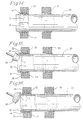
- FIGs 11 thru 16 The procedure for flaring the end of a pipe in accordance with the present invention is illustrated in Figures 11 thru 16.
- One begins with a selected pipe or tubing 20 shown in Figure 11 and preferably then slips flange 50 over the pipe as shown in Figure 12.
- the split metal ring is fitted over the pipe as shown in Figure 13. This assembly is placed in a flaring machine where a clamp 30 comprised of top 32 and bottom 34 will close pressing the split ring against pipe 20. Projections from the split ring will bite into the pipe holding it in place.
Landscapes
- Engineering & Computer Science (AREA)
- General Engineering & Computer Science (AREA)
- Mechanical Engineering (AREA)
- Flanged Joints, Insulating Joints, And Other Joints (AREA)
- Non-Disconnectible Joints And Screw-Threaded Joints (AREA)
- Magnetic Resonance Imaging Apparatus (AREA)
- Mutual Connection Of Rods And Tubes (AREA)
Description
- The invention relates to a method of gauging and coupling a metal pipe while the end of the pipe is being flared and thereafter coupling the flared pipe to another pipe or other device.
- Pipes and tubing are used to carry a variety of fluids, some are liquids and others are gases. These fluids may be under substantial pressures or at standard pressure. Therefore, pipes and tubing are rated according to the fluid pressures which the conduit can carry without rupturing. A particular conduit is considered to be a pipe or tubing depending upon the wall thickness of the conduit, the industry or application in which it is being used, and sometimes upon whether it is plastic or metal. For present purposes and simplicity we will use the term pipe to encompass both pipe and tubing as those terms are used by those skilled in the art.
- In hydraulic connections it is quite common to utilize pipes in which the end of the pipe has been flared to form a collar which is placed to abut against a surface of the device to which the pipe is being connected. In order to create the flared end or collar it is customary to provide a clamping die which is pressed against the pipe to be flared at a specified distance away from the end of the pipe. This die typically will have a gripping surface containing teeth or threads which bite into the exterior surface of the pipe being held. The die is pressed against the end of the pipe to hold the pipe during flaring. The flaring process is performed by a flaring machine having an eccentric cone. That cone is pressed against the end of the pipe and rotated circumferentially about the end of the pipe to form a flare. The flare can be at any angle relative to the side of the pipe. For many applications a flat end seal is desired in which case the flare will be at a right angle relative to the exterior surface of the pipe. This pipe flaring practice is quite old, but there have been improvements in the flaring tools. An improved flaring tool and method of using the same for forming a transverse collar on the end of the metal pipe is disclosed in United States Patent No. 4,905,492.
- The dies used for clamping the metal ends of the pipe to be flared are quite expensive. Additionally, the clamping action against the pipe being held causes wear, particularly on the gripping surfaces of the dies. When those surfaces have become sufficiently worn the pipe being grasped will slip. Then the surface must be refinished or the die must be scrapped. A second problem with this practice is that a separate set of dies must be made for each diameter of pipe. Consequently, there is a need for a device which an be used in the flaring of pipe ends that will improve die life and enable one to use a single clamping die for holding pipes of more than one diameter.
- The art has used rings in couplings for flared and straight pipe. Some of these rings have teeth on the inside surface which will bite into the pipe as a nut or collar is drawn over the ring. Often, the exterior surface of the ring and the mating interior surface of the nut or collar are sloped so that the ring will be pressed against the pipe as the nut or collar are advanced. Examples of this type of coupling can be found in United States Patents Nos 2,165,621 to Donahue et al., 2,269,629 to Kreidel, and 4,809,418 to Burli. A further example can be found in Austrian Patent No. 227493 to Hawle. Today, this type of ring is most commonly used for plastic pipe. Whenever such rings have been used on flared pipe the ring has not been used in any way for or during the flaring process. Furthermore, most of the couplings which utilize such rings for plastic pipe contain rings which are not suitable for metal pipe.
- We provide a method of gauging and coupling a metal pipe having an actual diameter D which may be greater than or less than a nominal diameter Dnominal by a tolerance T, where D = Dnominal ± T, the method comprising the steps:
- (a) placing a tubular coupling flange around the metal pipe, the coupling flange having a conical inner surface;
- (b) placing a split ring around the metal pipe, the split ring having an internal diameter equal to the nominal diameter Dnominal of the metal pipe and a conical outer surface complementary to the conical inner surface of the coupling flange, and an axial peripheral split (8) with a width W equal to π x the tolerance T;
- (c) closing the split ring around the metal pipe if the actual diameter D of the metal pipe is less than the nominal diameter Dnominal;
- (d) rejecting the metal pipe as undersized if the metal pipe slips through the split ring when the split ring is fully closed;
- (e) moving the tubular coupling flange axially over the split ring;
- (f) rejecting the metal pipe as oversized if the coupling flange fails completely to receive the split ring; and
- (g) connecting the coupling flange to an object to which the metal pipe is to be coupled.
-
- Other objects and advantages of the invention will become apparent from a description of certain preferred embodiments shown in the drawings.
-
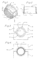
- Figure 1 is a perspective view of the split metal ring of the present invention.
- Figure 2 is a cross-sectional view taken along the line II-II of Figure 1.
- Figure 3 is an end view showing the front end of the split metal ring positioned over a metal pipe and held within a clamping die.
- Figure 4 is an end view showing the back end of the split metal ring positioned over a metal pipe and held within a clamping die.
- Figure 5 is an end view similar to Figure 4 showing the back end of a second split metal ring positioned over a smaller metal pipe and held within the same clamping die.
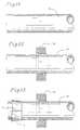
- Figure 6 is a perspective view of the coupling flange.
- Figure 7 is a side view of the coupling flange.
- Figure 8 is a sectional view taken along lines VIII-VIII of Figure 6.
- Figure 9 is a sectional view taken along lines IX-IX of Figure 6.
- Figure 10 is a side view partially in section showing pipes which have been flared and coupled together in accordance with the present invention.
- Figures 11 thru 16 are a sequence of side views partially in section showing the sequence for flaring a pipe in accordance with the present invention.
-
- As shown in Figures 1 and 2 we provide a
split metal ring 2 having aninside surface 3, anoutside surface 4, aback end 5 andfront end 6. Atransverse split 8 is provided in the ring. Splitmetal ring 2 is preferably made from spring steel and has a hardness greater than the hardness of the pipe around which it will be placed. As can be seen in Figure 2 theoutside surface 4 of the ring is tapered such that the ring is thicker at thefront end 6 than at theback end 5. We prefer to provide acollar 14 around thefront end 5 of the ring. Aradius 12 is provided on the front inside edge about which the pipe is flared. As can be seen for example in Figures 3 and 4, the split metal ring is placed around an end of apipe 20 to be flared. That pipe will have a nominal outside diameter, as for example 5.08 cm (2") and a wall thickness. Most users of metal pipe will specify pipe according to a nominal outside diameter, such as 5.08 cm (2") with a specified tolerance, such as 0.013 cm (0.005"). Consequently, any pipe which is within the range of 5.067 cm (1.995") and 5.093 cm (2.005") would be acceptable to the buyer. Because we make the distance betweenopposite sides split 8 equal to the specified tolerance the split ring will serve as a gauge to identify undersized pipe. If the ring is compressed to close the split and the pipe being held slips through the ring that pipe is undersized. - The just described method for identifying undersize pipe will typically be used when the pipe is being flared. During that process a die 30 will close around the
ring 2 and press the ring against thepipe 20 as shown in Figures 3 and 4. If the pipe has an outside diameter below the specified tolerances, splitmetal ring 2 will not securely clamp thepipe 20 after the clamping die has compressed thesplit ring 2 to closesplit 8. If after clamping, the pipe slips through the split ring the pipe is undersize and should not be used. For the pipe fitter working in the shop this is a very simple technique for determining whether a pipe meets the minimum specification. It involves no use of measuring tools and permits easy identification of undersized pipe by any worker. -
Split ring 2 also serves a second purpose. The ring is used to grip the pipe during flaring of the end of the pipe and when the pipe is coupled to another pipe or device. In a conventional prior art flaring process a clamping die, typically comprised of two halves, clamps the end of the pipe being flared such that there is direct contact between the die and the pipe being flared. Then a flaring tool bends the end of the pipe back against the clamping die to form the flare. When completed that flare could be perpendicular to the side wall of the pipe or at any desired angle relative to the side wall of a pipe. If the flare is made perpendicular to the side wall, then the clamping die also serves as the back, or anvil, against which the end of the pipe is pressed. - According to the present invention,
ring 2 is placed on the end of the pipe so that thering 2 will be between the clamping die 30 and thepipe 20 as shown in Figures 3 and 4. Clamping die 30 comprises atop half 32 andbottom half 34. The two arched shapedhalves ring 2. As the die closes, it forces splitring 2 against the outside surface of the pipe. This causes theprojections 7, which may be threads or annular ribs, to be pressed into the outside surface of thepipe 20, assuming that the pipe is not undersized. Because these projections are harder than the hardness of the pipe they will tend to score the pipe and become embedded in the outside surface of the pipe. After the split ring has been clamped about thepipe flaring tools threads 7 will bite into the pipe resisting the forces of theflaring tools pipe 20 and splitring 2 during flaring. As can be seen in Figures 15 and 16,collar 14 of the split metal ring extends over thefaces die halves split ring 2 and die 30 during flaring. Since it is not necessary to provide any teeth, threads or ribs on the flaring die 30 to grip splitring 2, there will be less wear of the die resulting in much longer die life. - As can be seen in Figures 14 thru 16, the flared
end 22 preferably will be perpendicular to the side of thepipe 20 to permit thepipe 20 to be face sealed against a similarly flared pipe, pump housing or other device. We prefer that the front face ofcollar 14 have a width equal or greater than the width of the portion of theflange 22 which will press against the ring. - The present system permits one to flange a
pipe 41 of smaller diameter than thepipe 20 shown in Figures 3 and 4 using thesame die 30. As shown in Figure 5 this is possible because we provide a thickersplit metal ring 42. The difference in thickness betweensplit metal ring 42 used forsmaller pipe 41 and splitmetal ring 2 used forpipe 20 is the difference in outside diameters of the two pipes. Because the same clamping die can be used for different diameter pipes a fewer number of dies are required to be maintained in inventory. Consequently, the present invention provides a significant savings over prior art flaring devices and techniques. - After the pipe has been flared it is ready to be connected to another pipe or device. To make the connection we provide a coupling flange shown in Figures 6, 7, 8 and 9. The
coupling flange 50 has afront surface 51 and backsurface 52. Bolt holes 54 are provided for connecting thecoupling flange 50 to asecond pipe 60 andcoupling flange 61 or other device (not shown) usingbolts 66 shown in Figure 10. We prefer thatcoupling flanges portions 55 of thecoupling flange 50 thicker for added strength. Couplingflange 50 has acentral bore 56 sized to receive thesplit ring 2. As can be seen more clearly in Figures 8 and 9, bore 56 is shaped to have atop portion 57 generally circular in diameter which extends from thetop surface 51 to ashoulder 58. The shoulder is sized to receive thecollar 14 ofsplit ring 2. Atshoulder 58 the bore will have a diameter d2 which will be less than the diameter d1 of the bore at thetop surface 51. Insidesurface 59 of the lower portion of the bore is tapered fromshoulder 58 tobottom 52. Consequently, the diameter d3 at the bottom of the coupling flange will be less than diameter d2 atshoulder 58. Diameters d1, d2 and d3 are chosen to be equal to the nominal value of-the outside diameter of the pipe to be held plus the specified tolerance and twice the thickness of thesplit ring 2 which is fitted within the coupling. Consequently, if an oversized pipe is placed within the ring the coupling flange cannot be drawn completely over the ring. For this reason thesplit metal ring 2 together with thecoupling flange 50 serve as a gauge to identify pipe which has an outside diameter greater than the specified nominal value plus the tolerance. - As can be seen from Figure 10,
coupling flange 50 is placed over thesplit ring 2 which is onpipe 20. Typically aseal plate 65 and gasket or O-ring 64 will be placed against the flared ends 22 and 62 of thepipes Bolts 66 will extend through thecoupling flanges seal plate 65. The bolts are then tightened to couple and sealpipes bolts 66 are tightened the inside surfaces 59 and 69 ofcoupling flanges outside surfaces 4 of the split rings 2. Since these surfaces are tapered this action will cause the threads or ribs on theinside surface 3 of the split rings 2 to maintain or increase their bites intopipes - We have found that the coupling shown in Figure 10 can be used for pipes and connections carrying fluids under pressure. For example, a 5.08 cm (2") section of ASTM-50 tubing was statically tested to determine if the coupling would leak at the rated pressure of the flange which was 20.6x10⁶ Pa (3000 psi). A coupling was created as shown in Figure 10. Oil was then pumped into the pipe to a pressure of 20.6x10⁶ Pa (3000 psi) and held at that pressure for one hour. No leaks of the coupling occurred. Based upon this result it is our expectation that the present coupling can be used at higher pressures of up to 34.5x10⁶ Pa (5000 psi) without leaking.
- The procedure for flaring the end of a pipe in accordance with the present invention is illustrated in Figures 11 thru 16. One begins with a selected pipe or
tubing 20 shown in Figure 11 and preferably then slipsflange 50 over the pipe as shown in Figure 12. Optionally, one could slip theflange 50 over the pipe from the opposite end (not shown) after flaring, but this may be inconvenient if the pipe is quite long. Next the split metal ring is fitted over the pipe as shown in Figure 13. This assembly is placed in a flaring machine where aclamp 30 comprised of top 32 and bottom 34 will close pressing the split ring againstpipe 20. Projections from the split ring will bite into the pipe holding it in place. An eccentric cone orother tools pipe 20 aroundradius edge 12 as shown in Figures 15 and 16. Then, the flaring tool and clamping die are removed. Now flange 50 can be moved oversplit ring 2 and the assembly is ready for connection to another pipe or device such as is shown in Figure 10.
Claims (10)
- A method of gauging and coupling a metal pipe (20) having an actual diameter D which may be greater than or less than a nominal diameter Dnominal by a tolerance T, where D = Dnominal ± T, the method comprising the steps:(a) placing a tubular coupling flange (50) around the metal pipe (20), the coupling flange (50) having a conical inner surface;(b) placing a split ring (2) around the metal pipe (20), the split ring (2) having an internal diameter equal to the nominal diameter Dnominal of the metal pipe (20) and a conical outer surface complementary to the conical inner surface of the coupling flange (50), and an axial peripheral split (8) with a width W equal to π x the tolerance T;(c) closing the split ring (2) around the metal pipe (20) if the actual diameter D of the metal pipe (20) is less than the nominal diameter Dnominal;(d) rejecting the metal pipe (20) as undersized if the metal pipe (20) slips through the split ring (2) when the split ring (2) is fully closed;(e) moving the tubular coupling flange (50) axially over the split ring (2);(f) rejecting the metal pipe (20) as oversized if the coupling flange (50) fails completely to receive the split ring (2); and(g) connecting the coupling flange (50) to an object to which the metal pipe (20) is to be coupled.
- A method according to claim 1, wherein the split ring (2) has a hardness greater than a hardness of the metal pipe (20) and an inner surface (3) having projections (7) extending therefrom.
- A method according to claim 2, wherein the projections (7) are one of annular ribs, threads and teeth.
- A method according to claim 2 or claim 3, wherein the projections (7) have a height of between 1 and 2 thousandths of an inch (0.025 to 0.051 mm).
- A method according to any preceding claim, wherein the conical outer surface of the split ring (2) is such that there is a major thickness at a first end (6) of the split ring (2) and a minor thickness at a second, opposite, end (5) thereof, and wherein the split ring (2) has a shoulder (14) extending outwardly from the first end (6) of the split ring (2) and the coupling flange (50) has an annular recess (57) sized and positioned to receive the shoulder (14).
- A method according to any preceding claim, wherein step (c) is performed by clamping a die (30) around the conical outer surface of the split ring (2).
- A method according to claim 6, wherein the clamping die (30) has an inner surface sized and configured to mate with the conical outer surface of the split ring (2).
- A method according to any preceding claim, further comprising the step of flaring an end of the metal pipe (20).
- A method according to claim 8, wherein the flaring step is carried out by bending the end of the metal pipe (20) outwardly against a reaction shoulder formed by the split ring (2).
- A method according to claim 8 or claim 9, further comprising the step of placing a seal (64,65) adjacent the flared end (22,62) of the metal pipe (20).
Priority Applications (4)
| Application Number | Priority Date | Filing Date | Title |
|---|---|---|---|
| AU40648/95A AU710658B2 (en) | 1995-12-22 | 1995-12-22 | Device for coupling and flaring a metal pipe |
| EP96301209A EP0793046B1 (en) | 1995-12-22 | 1996-03-01 | Method of gauging and coupling a metal pipe |
| DE69617388T DE69617388T2 (en) | 1995-12-22 | 1996-03-01 | Method of teaching and connecting a metal pipe |
| ES96301209T ES2168437T3 (en) | 1995-12-22 | 1996-03-01 | METHOD OF CALIBRATION AND COUPLING OF A METAL TUBE. |
Applications Claiming Priority (2)
| Application Number | Priority Date | Filing Date | Title |
|---|---|---|---|
| AU40648/95A AU710658B2 (en) | 1995-12-22 | 1995-12-22 | Device for coupling and flaring a metal pipe |
| EP96301209A EP0793046B1 (en) | 1995-12-22 | 1996-03-01 | Method of gauging and coupling a metal pipe |
Publications (2)
| Publication Number | Publication Date |
|---|---|
| EP0793046A1 EP0793046A1 (en) | 1997-09-03 |
| EP0793046B1 true EP0793046B1 (en) | 2001-11-28 |
Family
ID=25625277
Family Applications (1)
| Application Number | Title | Priority Date | Filing Date |
|---|---|---|---|
| EP96301209A Expired - Lifetime EP0793046B1 (en) | 1995-12-22 | 1996-03-01 | Method of gauging and coupling a metal pipe |
Country Status (4)
| Country | Link |
|---|---|
| EP (1) | EP0793046B1 (en) |
| AU (1) | AU710658B2 (en) |
| DE (1) | DE69617388T2 (en) |
| ES (1) | ES2168437T3 (en) |
Families Citing this family (2)
| Publication number | Priority date | Publication date | Assignee | Title |
|---|---|---|---|---|
| CN113187955B (en) * | 2021-05-29 | 2021-12-03 | 广东骏太建筑安装有限公司 | High-precision positioning and mounting device for common-plate flange air pipes |
| CN113926934A (en) * | 2021-10-20 | 2022-01-14 | 中船黄埔文冲船舶有限公司 | Flaring device for marine metal pipe |
Family Cites Families (12)
| Publication number | Priority date | Publication date | Assignee | Title |
|---|---|---|---|---|
| FR685502A (en) * | 1929-02-23 | 1930-07-11 | Schneider & Cie | Improvements to flanged assemblies for pipes |
| US2165621A (en) * | 1938-05-20 | 1939-07-11 | Scovill Manufacturing Co | Pipe connection |
| US2269629A (en) * | 1939-02-09 | 1942-01-13 | Kreidel Hans | Tube coupling |
| AT227493B (en) * | 1960-09-26 | 1963-05-27 | Erwin Hawle | Connection connection for smooth pipes, especially plastic pipes |
| FR81547E (en) * | 1962-04-27 | 1963-10-04 | Conducto | Fitting for tubes and sheaths of all kinds |
| US3284112A (en) * | 1963-12-11 | 1966-11-08 | Horace T Potts Company | Rotatable flange adjustable pipe coupling |
| FR2232722B2 (en) * | 1973-06-08 | 1976-12-17 | Oclau Societe Expl Des Brevets | |
| EP0186716A1 (en) * | 1984-12-19 | 1986-07-09 | Coenraad Cornelius Delport | Pipe couplings |
| US4735442A (en) * | 1985-09-13 | 1988-04-05 | J. & R. Gunzenhauser Ag | Plastic pipe connection |
| FI89137C (en) * | 1987-02-24 | 1993-08-25 | Gs Hydro Oy | Method and apparatus for forming a collar at the end of a metal tube at a substantially right angle with respect to the longitudinal direction of the tube |
| DE4127498A1 (en) * | 1991-08-20 | 1993-02-25 | Dietzel Hydraulik Gmbh & Co Kg | Pipe connection using cutting ring - has inner circumferential groove holding widened end of pipe |
| JP3488331B2 (en) * | 1996-02-21 | 2004-01-19 | カルソニックカンセイ株式会社 | Pipe fitting with flange and method of manufacturing the same |
-
1995
- 1995-12-22 AU AU40648/95A patent/AU710658B2/en not_active Ceased
-
1996
- 1996-03-01 DE DE69617388T patent/DE69617388T2/en not_active Expired - Fee Related
- 1996-03-01 EP EP96301209A patent/EP0793046B1/en not_active Expired - Lifetime
- 1996-03-01 ES ES96301209T patent/ES2168437T3/en not_active Expired - Lifetime
Also Published As
| Publication number | Publication date |
|---|---|
| AU710658B2 (en) | 1999-09-23 |
| EP0793046A1 (en) | 1997-09-03 |
| AU4064895A (en) | 1997-06-26 |
| DE69617388D1 (en) | 2002-01-10 |
| ES2168437T3 (en) | 2002-06-16 |
| DE69617388T2 (en) | 2002-08-14 |
Similar Documents
| Publication | Publication Date | Title |
|---|---|---|
| US4328983A (en) | Positive seal steel coupling apparatus and method therefor | |
| US6360415B1 (en) | Flanged pipe unit and method of producing same | |
| US5484174A (en) | Pipe coupling and method of joining materials | |
| US4109941A (en) | Coupling for plastic pipe | |
| US4980961A (en) | Method of forming a double upset tube assembly | |
| US4095825A (en) | Taper pipe joint | |
| US8745869B2 (en) | Screwed pipe joint and method for the production thereof | |
| US4480861A (en) | Pipe joint and apparatus therefor | |
| US4930816A (en) | Joining structures for metal pipes | |
| CA1241979A (en) | Tubing fitting | |
| US20020041098A1 (en) | Pipe-fitting with flexible sleeve and cinching nut | |
| EP0086509B1 (en) | Unitary clamp action fitting | |
| CA1303094C (en) | Pipe union assembly | |
| US3338598A (en) | Coupling method and devices for lined pipe | |
| US4769892A (en) | Pipe joining method | |
| US5518275A (en) | Device for coupling and flaring a metal pipe | |
| US4629220A (en) | Method and apparatus for quick-coupling connecting nipple for plastic pipe | |
| US12018778B2 (en) | Integrated joining system in tubular fluid distribution elements | |
| US5911447A (en) | Pipe connector | |
| US4486035A (en) | Reusable coupling | |
| US5823579A (en) | Device for coupling a flared metal pipe | |
| US20040046388A1 (en) | Tubular connection floating shoulder ring | |
| EP0793046B1 (en) | Method of gauging and coupling a metal pipe | |
| CA2165646C (en) | Device for coupling and flaring a metal pipe | |
| EP0220150B1 (en) | Pipe joint |
Legal Events
| Date | Code | Title | Description |
|---|---|---|---|
| PUAI | Public reference made under article 153(3) epc to a published international application that has entered the european phase |
Free format text: ORIGINAL CODE: 0009012 |
|
| AK | Designated contracting states |
Kind code of ref document: A1 Designated state(s): BE DE ES FI FR GB IT LU NL SE |
|
| 17P | Request for examination filed |
Effective date: 19980223 |
|
| 17Q | First examination report despatched |
Effective date: 19991109 |
|
| RTI1 | Title (correction) |
Free format text: METHOD OF GAUGING AND COUPLING A METAL PIPE |
|
| GRAG | Despatch of communication of intention to grant |
Free format text: ORIGINAL CODE: EPIDOS AGRA |
|
| GRAG | Despatch of communication of intention to grant |
Free format text: ORIGINAL CODE: EPIDOS AGRA |
|
| GRAH | Despatch of communication of intention to grant a patent |
Free format text: ORIGINAL CODE: EPIDOS IGRA |
|
| GRAH | Despatch of communication of intention to grant a patent |
Free format text: ORIGINAL CODE: EPIDOS IGRA |
|
| GRAA | (expected) grant |
Free format text: ORIGINAL CODE: 0009210 |
|
| AK | Designated contracting states |
Kind code of ref document: B1 Designated state(s): BE DE ES FI FR GB IT LU NL SE |
|
| REG | Reference to a national code |
Ref country code: GB Ref legal event code: IF02 |
|
| REF | Corresponds to: |
Ref document number: 69617388 Country of ref document: DE Date of ref document: 20020110 |
|
| REG | Reference to a national code |
Ref country code: ES Ref legal event code: FG2A Ref document number: 2168437 Country of ref document: ES Kind code of ref document: T3 |
|
| PLBE | No opposition filed within time limit |
Free format text: ORIGINAL CODE: 0009261 |
|
| STAA | Information on the status of an ep patent application or granted ep patent |
Free format text: STATUS: NO OPPOSITION FILED WITHIN TIME LIMIT |
|
| 26N | No opposition filed | ||
| PGFP | Annual fee paid to national office [announced via postgrant information from national office to epo] |
Ref country code: NL Payment date: 20080331 Year of fee payment: 13 Ref country code: IT Payment date: 20080326 Year of fee payment: 13 Ref country code: GB Payment date: 20080328 Year of fee payment: 13 Ref country code: FI Payment date: 20080326 Year of fee payment: 13 |
|
| PGFP | Annual fee paid to national office [announced via postgrant information from national office to epo] |
Ref country code: LU Payment date: 20080402 Year of fee payment: 13 Ref country code: FR Payment date: 20080318 Year of fee payment: 13 Ref country code: DE Payment date: 20080319 Year of fee payment: 13 |
|
| PGFP | Annual fee paid to national office [announced via postgrant information from national office to epo] |
Ref country code: BE Payment date: 20080317 Year of fee payment: 13 |
|
| BERE | Be: lapsed |
Owner name: *TUBE-MAC INDUSTRIES LTD Effective date: 20090331 |
|
| PG25 | Lapsed in a contracting state [announced via postgrant information from national office to epo] |
Ref country code: FI Free format text: LAPSE BECAUSE OF NON-PAYMENT OF DUE FEES Effective date: 20090301 |
|
| EUG | Se: european patent has lapsed | ||
| GBPC | Gb: european patent ceased through non-payment of renewal fee |
Effective date: 20090301 |
|
| NLV4 | Nl: lapsed or anulled due to non-payment of the annual fee |
Effective date: 20091001 |
|
| REG | Reference to a national code |
Ref country code: FR Ref legal event code: ST Effective date: 20091130 |
|
| PG25 | Lapsed in a contracting state [announced via postgrant information from national office to epo] |
Ref country code: DE Free format text: LAPSE BECAUSE OF NON-PAYMENT OF DUE FEES Effective date: 20091001 |
|
| PG25 | Lapsed in a contracting state [announced via postgrant information from national office to epo] |
Ref country code: NL Free format text: LAPSE BECAUSE OF NON-PAYMENT OF DUE FEES Effective date: 20091001 Ref country code: BE Free format text: LAPSE BECAUSE OF NON-PAYMENT OF DUE FEES Effective date: 20090331 |
|
| PG25 | Lapsed in a contracting state [announced via postgrant information from national office to epo] |
Ref country code: GB Free format text: LAPSE BECAUSE OF NON-PAYMENT OF DUE FEES Effective date: 20090301 Ref country code: FR Free format text: LAPSE BECAUSE OF NON-PAYMENT OF DUE FEES Effective date: 20091123 |
|
| PGFP | Annual fee paid to national office [announced via postgrant information from national office to epo] |
Ref country code: ES Payment date: 20100408 Year of fee payment: 15 |
|
| PGFP | Annual fee paid to national office [announced via postgrant information from national office to epo] |
Ref country code: SE Payment date: 20100310 Year of fee payment: 15 |
|
| PG25 | Lapsed in a contracting state [announced via postgrant information from national office to epo] |
Ref country code: IT Free format text: LAPSE BECAUSE OF NON-PAYMENT OF DUE FEES Effective date: 20090301 |
|
| PG25 | Lapsed in a contracting state [announced via postgrant information from national office to epo] |
Ref country code: LU Free format text: LAPSE BECAUSE OF NON-PAYMENT OF DUE FEES Effective date: 20090301 |
|
| PG25 | Lapsed in a contracting state [announced via postgrant information from national office to epo] |
Ref country code: SE Free format text: LAPSE BECAUSE OF NON-PAYMENT OF DUE FEES Effective date: 20090302 |
|
| REG | Reference to a national code |
Ref country code: ES Ref legal event code: FD2A Effective date: 20120423 |
|
| PG25 | Lapsed in a contracting state [announced via postgrant information from national office to epo] |
Ref country code: ES Free format text: LAPSE BECAUSE OF NON-PAYMENT OF DUE FEES Effective date: 20110302 |