EP0792666A2 - Adjustable back strap for diving and swimming equipment - Google Patents
Adjustable back strap for diving and swimming equipment Download PDFInfo
- Publication number
- EP0792666A2 EP0792666A2 EP97830047A EP97830047A EP0792666A2 EP 0792666 A2 EP0792666 A2 EP 0792666A2 EP 97830047 A EP97830047 A EP 97830047A EP 97830047 A EP97830047 A EP 97830047A EP 0792666 A2 EP0792666 A2 EP 0792666A2
- Authority
- EP
- European Patent Office
- Prior art keywords
- strap
- buckle
- coupling member
- female
- strap according
- Prior art date
- Legal status (The legal status is an assumption and is not a legal conclusion. Google has not performed a legal analysis and makes no representation as to the accuracy of the status listed.)
- Granted
Links
Images

Classifications
-
- A—HUMAN NECESSITIES
- A44—HABERDASHERY; JEWELLERY
- A44B—BUTTONS, PINS, BUCKLES, SLIDE FASTENERS, OR THE LIKE
- A44B11/00—Buckles; Similar fasteners for interconnecting straps or the like, e.g. for safety belts
- A44B11/25—Buckles; Similar fasteners for interconnecting straps or the like, e.g. for safety belts with two or more separable parts
- A44B11/26—Buckles; Similar fasteners for interconnecting straps or the like, e.g. for safety belts with two or more separable parts with push-button fastenings
- A44B11/266—Buckles; Similar fasteners for interconnecting straps or the like, e.g. for safety belts with two or more separable parts with push-button fastenings with at least one push-button acting parallel to the main plane of the buckle and perpendicularly to the direction of the fastening action
-
- A—HUMAN NECESSITIES
- A63—SPORTS; GAMES; AMUSEMENTS
- A63B—APPARATUS FOR PHYSICAL TRAINING, GYMNASTICS, SWIMMING, CLIMBING, OR FENCING; BALL GAMES; TRAINING EQUIPMENT
- A63B31/00—Swimming aids
- A63B31/08—Swim fins, flippers or other swimming aids held by, or attachable to, the hands, arms, feet or legs
- A63B31/10—Swim fins, flippers or other swimming aids held by, or attachable to, the hands, arms, feet or legs held by, or attachable to, the hands or feet
- A63B31/11—Swim fins, flippers or other swimming aids held by, or attachable to, the hands, arms, feet or legs held by, or attachable to, the hands or feet attachable only to the feet
Definitions
- the present invention is generally related to diving and swimming equipment or appliances, such as flippers, masks, goggles and the like having a seat adapted to be engaged by or onto a part of the user's body (foot-face).
- the invention is directed to a back strap for such diving equipment of the type including a substantially elastic band whose ends are connected to respective attachment members to be fastened to the equipment, at opposite sides of said seat, and at least one of which is provided with adjustment means to vary the length of the strap.
- Straps of the above-referenced type are known, for instance, from Italian Utility Model n. 197.555 in the name of the same Applicant, and from U.S. Patent No. 4,607,398.
- the attachment members of the strap which are permanently fastened to the diving equipment structure, are provided with an adjustment device formed by a swinging latching lever which is normally kept, under the action of a spring, into engagement with latch teeth formed along the corresponding strap end, which is turned around a pin carried by the body of the attachment member.
- adjusting the strap length is comfortable an easy but, particularly as far as flippers are concerned, wearing and unwearing may result remarkably laborious and tiring.
- unwearing requires lengthening the strap at one or both ends and then disengagement thereof from the user's heel by sliding the strap beyond the foot.
- each attachment member has a buckle construction, with a stationary part permanently coupled with a respective side of the flipper and a movable part carrying the adjustment device, which can be connected to each other by to perform quick opening and closing of the strap.
- This snap-fit system corresponds to that of a usual buckle employed since long in the most various applications, and release of which requires elastically pushing the two latch levers of the movable part towards each other, by at least two fingers of the user's hand, so has to perform disengagement thereof from the stationary part.
- the object of the present invention is to overcome the above drawbacks, and namely to provide a back strap of the above-referenced type whose opening and quick closing are made more comfortable and convenient, with a minimum effort, and by means of a construction which is not negatively affecting functionality of the adjustment means of the strap length.
- a further object of the present invention is to provide a back strap of the above-referenced type whose buckle means performing opening and closing thereof are constructively simple, functional and inexpensive.
- Another object of the invention is to provide a back strap of the above-referenced type which, particularly as far as application to a flipper is concerned, does not necessarily require a manual intervention for opening thereof.
- a further object of the invention is to provide a back strap of the above-referenced type which, also in the opening position of the buckle means, remains permanently anchored to the diving equipment at both end thereof, thus preventing any risks of accidental lost.
- an adjustable back strap for diving and swimming equipment of the type set-forth at the beginning is primarily characterized in that it is formed by two distinct and separate strap sections, each of which is connected at one end to a respective attachment member, and that said buckle means are applied to the ends of said two strap sections opposite to the respective attachment members.
- the buckle means may comprise in practice a single buckle having quick opening and closing performance, which is preferably arranged substantially in the central area of the strap. Accordingly the two strap sections have a symmetrical configuration; alternatively, asymmetrical arrangements may also be contemplated, locating the buckle in a lateral area of the strap.
- a relatively soft bearing element is associated to the buckle to lay against the part of the user's body.
- the buckle comprises at least a female coupling member and a male coupling member permanently anchored to the one and, respectively, to the other strap section, these male and female coupling members being snap engageable with each other upon mutual engagement thereof along a first direction, and being disengageable from each other following application from outside of a thrust along a second direction perpendicular to the first direction.
- the buckle conveniently comprises a movable release member separated from said male and female coupling members and elastically displaceable from an inoperative position towards an operative position to release said male coupling member relative to said female coupling member along said second direction.
- the back strap according to the invention provides the following advantages:
- the strap according to the invention is applicable in a particularly advantageous way to flippers, but can be equally usefully employed in the case of other diving and swimming equipment, such as masks and goggles.
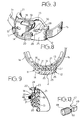
- reference F generally designates the rear portion of a swimming flipper, of a generally conventional type for instance disclosed and illustrated in U.S. Patents No. 5,163,859; 5,435,764; 5,324,219 and 5,358,439 in the name of the same Applicant.
- the flipper F comprises a relatively rigid blade P and a shoe S, made of a relatively soft material, permanently connected to the blade P by overmoulding and open at its end opposite to the blade P.
- the shoe S thus defines a receptacle R which is rearwardly open and lowerly delimited by a base or sole B of the same relatively rigid material forming the blade P.
- Two outer and juxtaposed head pins M normally formed integrally with the blade P upon moulding thereof, are
- These pins M define anchoring elements for an adjustable back strap according to the invention, generally designated as 1.
- the adjustable back strap 1 is formed by two strap sections 1a, 1b, which are distinct and separate from each other and both normally made of elastomeric material.
- the two strap sections 1a, 1b can be mutually connected and disconnected at the respective inner ends by means of a quickly openable and closable buckle 2 which, in the case of the shown example, is located in correspondence of the central area of the strap 1, whereby the two sections 1a, 1b have same length.
- the buckle 2 is for instance located laterally, whereby the strap sections la, 1b have a non-symmetrical design.
- each strap section 1a, 1b is connected to a respective attachment member 3, of a generally conventional type incorporating an adjustment device provided to vary the operative length of each strap section 1a, 1b, i.e. the total useful length of the strap 1.
- each attachment member 3 may be, for instance, of the type disclosed and illustrated in already mentioned Italian utility model No. 197.555 and in U.S. Patent No. 4,607,398.
- each attachment member 3 comprises a body 4 formed with a double aperture 5 for engagement and permanent anchoring thereof to a respective lateral head pin M of the flipper F, and also carrying a roller 6 around which the outer end of the respective strap section 1a, 1b is wound.
- This inner end, whose tip tail is designated as 7, is formed with a number of transverse tooth projections 8 cooperating, in a known way, with a latching lever 9 which is swingable around a pin 10 and is normally kept, by the action of a spring member not illustrated, into engagement with the tooth projections 8.
- the buckle 2 is essentially formed by a female coupling member 11 and by a male coupling member 12 adapted to be snap connected to each other and quickly disconnected.
- the female coupling member 11 comprises a base plate 13 having an arcuated design, whose curvature corresponds to the average back curvature of a foot heel, and which is made of a relatively rigid material preferably consisting of a moulded thermoplastic material.
- the base plate 13 is rigid, since for instance integrally formed by moulding, with a shell-like body 14 having, near to its outer side, a recess 15 (figure 8) housing therein an enlarged end head 16 of the strap section la.
- This strap section la is thus permanently anchored to the female coupling member 11, whose opposite side is open and has an oblique edge 17.
- the body 14 is formed with a window-like opening 18 (figures 3 and 7) whose outer edge, i.e. the one facing towards the oblique edge 17, defines a hooking member 19, the function of which will be clarified here below.
- the body 14 is formed with a grooved guide appendage 20 which, owing to the oblique configuration of the edge 17, projects outwardly from the side opposite to the strap section 1a.
- the face of the base plate 13 which is opposite to the body 14 is covered with a pad member 21 made of a relatively soft and flexible material, for instance elastomeric material or thermoplastic rubber, which is secured to the female coupling member assembly 14 normally by overmoulding.
- a pad member 21 made of a relatively soft and flexible material, for instance elastomeric material or thermoplastic rubber, which is secured to the female coupling member assembly 14 normally by overmoulding.
- the perimetral edges of the base plate 13 are incorporated within the pad element 21, i.e. are entirely covered thereby.
- the pad element 21 is integrally formed with a bracket portion 22 projecting in a cantilever fashion above the window opening 18 of the body 14.
- the push button 23 constitutes a movable release member, physically separated from the male and female coupling members 11, 12, by means of which opening of the buckle 2 is to be operated.
- the upper end of the push button 23, secured to the bracket part 22 through a restrained-joint connection or any other equivalent system, may be conveniently covered by an enlarged anti-slip element 24 fixed onto the bracket part 22.
- the male coupling member 12 comprises a body 25, also having a generally shell-like configuration and normally made of a moulded thermoplastic material, which is formed in correspondence of its outer side with a recess 26 housing an enlarged end head 27 of the strap section 1b, which is thus permanently anchored to the male coupling member 12.
- the inner side of the body 25 is open and has an oblique edge 28 complementary to the oblique edge 17 of the body 14 of the female coupling member 11.
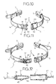
- Reference 47 designates a safety-catch member, preferably but not necessarily provided for preventing accidental opening of the buckle 2.
- the safety catch member 47 comprises a slider having at one end a manually operable outer knurled knob 48 projecting rearwardly of the female coupling member 11, at the opposite end an inner stop head 49 placed beneath the arm 29, and an intermediate shank 50 (normally having a prismatic shape) slidably fitted under friction along a horizontal slot 51 of the female coupling member 11.
- the safety catch 47 is displaceable along the slot 51 between a lock position (towards the right in the drawings) in which the even in case of pressure upon the push button 23, and an unlock position (towards the left in the drawings) in which elastic deformation of the arm 29 following operation of the push button 23 is instead enabled. Retaining formations of the safety catch 47 in either positions can also be provided.
- the buckle 2 of the strap 1 has a general configuration conceptually similar to that of a buckle for motorvehicle safety belts, having a push button for quick release of a male hooking member relative to a female hooking member.
- the elastic member performing quick separation between the two male and female hooking members (which in the buckles for motorvehicle safety belts is constituted by a suitable inner spring) is, according to the invention, formed by the two strap sections 1a, 1b themselves which, in use with the buckle 2 in the closed condition, are kept under resilient traction.
- the user can easily fit his foot into the flipper receptacle R, and then restrain the heel relative thereto following closure of the buckle 2. To do so, it is sufficient to bring the female coupling member 11 and the male coupling member 12 together, introducing and sliding the guide appendage 20 of the former into the tubular guide element 31 of the latter, and then fitting the arm 29 of the latter into the body 14 of the former, after positioning the safety catch 47 in the unlock condition. Following this action, the hooking tooth 30 snap-fits within the window opening 18, thus engaging behind the hooking member 19 so as to lock the male coupling member 12 relative to the female coupling member 11, such as shown in detail in figures 7 and 8.
- opening of the buckle 2 according to the preferred embodiment of figures 1-9 is in practice carried out following a thrust applied from outside along one direction which is at right angle relative to the coupling/uncoupling direction of the female and male coupling members 11, 12.
- This direction might however also be oblique or parallel with respect to the coupling/uncoupling direction between the female and male coupling members 11, 12, as in the case of the alternative embodiment which will be further disclosed with reference to figure 10.
- the strap 1 according to the invention can be applied not only to flippers, but also to any other diving or swimming equipment having a seat adapted to be engaged by a part of the user's body and to be closed thereagainst.
- Examples of such equipment include diving masks, swimming goggles and the like.
- the two strap sections 1a, 1b will be permanently anchored at the opposite sides of the equipment body (the frame carrying the transparent visor of a diving mask, the frames carrying respective transparent lenses of the goggles), and the arrangement of the buckle 2 will be substantially identical to that previously disclosed.
- the only remarkable difference may consists of a different and lower curvature of the base plate 13 and related soft pad element 21 of the female coupling member 11.
- the release push button 23 could in these cases be arranged below instead of above the buckle 2. This arrangement can evidently be obtained simply turning the buckle 2 upside down, and accordingly the thrust onto the release push button 23 to operate opening of the buckle 2 will be directed from below upwardly.
- This arrangement may also be employed when the buckle 2 is applied to a flipper: in this case, opening could be operated by the same user's foot wearing the flipper, abutting the push button 23 against any available reaction surface.
- the buckle 2 may be positioned, instead of in correspondence of the central area of the strap 1, in a lateral area thereof: accordingly the two strap sections 1a, 1b shall evidently have an uneven length.
- the locking and unlocking system between the two elements constituting the buckle 2 may be different from that disclosed and illustrated in the example of figures 1-9, and for instance be provided, as shown in figure 10, with a conventional construction such as disclosed and shown in wherein the male coupling member 12 has a pair of juxtaposed springing arms 41 with respective hooking teeth 42 adapted to snap-fit engage corresponding recesses 43 of the female coupling member 11.
- the male coupling member 12 has a springing wing 44 adapted to be fitted into the female coupling member 11 and formed with a button 45 snap-fit engageable into a back hole 46 of this female coupling member 11.
- This solution also constructively simple, provides with respect to the embodiment of figure 10 the advantage of being operable, so as to open the buckle 2, by pressing the button 45 with a single user's finger or even with his foot.
- the construction and arrangement of the push button 23 previously disclosed with reference to the preferred embodiment of figures 1-9 may be different: in particular, the elastic member keeping this push button 3 in its inoperative position could be constituted, instead of the springing bracket part 22 integrated with the pad element 21, by a suitable return spring. Additionally the anti-slip element 24 may have a concave shape so as to allow convenient operation thereof by means of an auxiliary tool, for instance constituted by a simple rod equipping or anyhow available to the user. Lastly, the push button 23 may be integrated with a projecting lever or arm, for instance upwardly inclined, for a more convenient actuation thereof.
Abstract
Description
- The present invention is generally related to diving and swimming equipment or appliances, such as flippers, masks, goggles and the like having a seat adapted to be engaged by or onto a part of the user's body (foot-face).
- More particularly, the invention is directed to a back strap for such diving equipment of the type including a substantially elastic band whose ends are connected to respective attachment members to be fastened to the equipment, at opposite sides of said seat, and at least one of which is provided with adjustment means to vary the length of the strap.
- Straps of the above-referenced type are known, for instance, from Italian Utility Model n. 197.555 in the name of the same Applicant, and from U.S. Patent No. 4,607,398. In both cases the attachment members of the strap, which are permanently fastened to the diving equipment structure, are provided with an adjustment device formed by a swinging latching lever which is normally kept, under the action of a spring, into engagement with latch teeth formed along the corresponding strap end, which is turned around a pin carried by the body of the attachment member.
- According to this solution, adjusting the strap length is comfortable an easy but, particularly as far as flippers are concerned, wearing and unwearing may result remarkably laborious and tiring. Namely, unwearing requires lengthening the strap at one or both ends and then disengagement thereof from the user's heel by sliding the strap beyond the foot.
- In order to overcome this drawback, U.S. Patent No. 4,795,385 provides that each attachment member has a buckle construction, with a stationary part permanently coupled with a respective side of the flipper and a movable part carrying the adjustment device, which can be connected to each other by to perform quick opening and closing of the strap. This snap-fit system corresponds to that of a usual buckle employed since long in the most various applications, and release of which requires elastically pushing the two latch levers of the movable part towards each other, by at least two fingers of the user's hand, so has to perform disengagement thereof from the stationary part. Considering the encumbrance of the buckle as a whole, the size of the latching lever of each strap adjustment system is necessarily limited, whereby the length of the respective lever arm through which release of the strap can be operated is consequently limited. Accordingly, operation of the adjustment levers may result difficult and requires a remarkable effort.
- Even opening of the or each buckle, besides necessarily requiring a manual intervention, is uncomfortable and involves a certain effort, also owing to the relatively advanced position of these buckles relative to the user's foot. This inconvenience is particularly critical in connection with unwearing flippers by a diver equipped with a full diving gear.
- The object of the present invention is to overcome the above drawbacks, and namely to provide a back strap of the above-referenced type whose opening and quick closing are made more comfortable and convenient, with a minimum effort, and by means of a construction which is not negatively affecting functionality of the adjustment means of the strap length.
- A further object of the present invention is to provide a back strap of the above-referenced type whose buckle means performing opening and closing thereof are constructively simple, functional and inexpensive.
- Another object of the invention is to provide a back strap of the above-referenced type which, particularly as far as application to a flipper is concerned, does not necessarily require a manual intervention for opening thereof.
- A further object of the invention is to provide a back strap of the above-referenced type which, also in the opening position of the buckle means, remains permanently anchored to the diving equipment at both end thereof, thus preventing any risks of accidental lost.
- These and further objects are achieved, according to the invention, by virtue of the fact that an adjustable back strap for diving and swimming equipment of the type set-forth at the beginning is primarily characterized in that it is formed by two distinct and separate strap sections, each of which is connected at one end to a respective attachment member, and that said buckle means are applied to the ends of said two strap sections opposite to the respective attachment members.
- The buckle means may comprise in practice a single buckle having quick opening and closing performance, which is preferably arranged substantially in the central area of the strap. Accordingly the two strap sections have a symmetrical configuration; alternatively, asymmetrical arrangements may also be contemplated, locating the buckle in a lateral area of the strap.
- According to a preferred embodiment of the invention, a relatively soft bearing element is associated to the buckle to lay against the part of the user's body.
- Preferably the buckle comprises at least a female coupling member and a male coupling member permanently anchored to the one and, respectively, to the other strap section, these male and female coupling members being snap engageable with each other upon mutual engagement thereof along a first direction, and being disengageable from each other following application from outside of a thrust along a second direction perpendicular to the first direction.
- To such effect, the buckle conveniently comprises a movable release member separated from said male and female coupling members and elastically displaceable from an inoperative position towards an operative position to release said male coupling member relative to said female coupling member along said second direction.
- By virtue of the above features, the back strap according to the invention provides the following advantages:
- operation of the adjustment means to vary the strap length is extremely easy: in order to shorten the strap and increase the retaining force thereof, it is sufficient to pull the two tails thereof coming out from the attachment members incorporating the adjustment means; to lengthen the strap and thus decrease its retaining force, it is sufficient to operate the latch levers of the adjustment means which, due to a longer lever arm thereof, are particularly functional;
- opening of the strap is particularly comfortable, can be performed by a single finger of the user's hand and, due to the rear positioning of the buckle, the user has not to elongate excessively his arm;
- particularly as far as application of the back strap to a flipper is concerned, opening thereof can be easily and conveniently carried out by the heel or the sole of the other foot, either standing on a boat or wharf, or staying in the water;
- wearing again the equipment is easy, without any need of modifying the adjustment of the strap length: in this case it is in fact sufficient to close again the buckle behind the corresponding part of the user's body.
- The strap according to the invention is applicable in a particularly advantageous way to flippers, but can be equally usefully employed in the case of other diving and swimming equipment, such as masks and goggles.
- The invention will now be disclosed in detail with reference to the accompanying drawings, related to application of the back strap to a flipper, wherein:
- figure 1 is a perspective and partially exploded view showing a back strap according to a first embodiment of the invention applied to a swimming flipper and shown in the closed condition thereof,
- figure 2 is a view similar to figure 1 showing part of the back strap in the opened condition,
- figure 3 is a view similar to figure 2 but partially broken,
- figure 4 is a front elevational view according to arrow IV of figure 1,
- figure 5 is a lateral elevational view of figure 4,
- figure 6 is a top plan view of figure 4,
- figure 7 is a vertically sectioned view along line VII-VII of figure 6,
- figure 8 is a horizontally sectioned view along line VIII-VIII of figure 4,
- figure 9 is a vertically sectioned view along line IX-IX of figure 4,
- figure 10 is a diagrammatic perspective view showing a first variant of the back strap according to the invention depicted in the open condition,
- figure 11 is a view similar to figure 10 of a second variant of the invention,
- figure 12 is a sectioned view along line XII-XII of figure 11, and
- figure 13 is a perspective and enlarged view of a detail of the back strap shown in figures 1 trough 9.
- Referring initially to figures 1-9 of the drawings, reference F generally designates the rear portion of a swimming flipper, of a generally conventional type for instance disclosed and illustrated in U.S. Patents No. 5,163,859; 5,435,764; 5,324,219 and 5,358,439 in the name of the same Applicant. Briefly, the flipper F comprises a relatively rigid blade P and a shoe S, made of a relatively soft material, permanently connected to the blade P by overmoulding and open at its end opposite to the blade P. The shoe S thus defines a receptacle R which is rearwardly open and lowerly delimited by a base or sole B of the same relatively rigid material forming the blade P. Two outer and juxtaposed head pins M, normally formed integrally with the blade P upon moulding thereof, are
- These pins M define anchoring elements for an adjustable back strap according to the invention, generally designated as 1.
- According to a first aspect of the invention, the
adjustable back strap 1 is formed by twostrap sections strap sections closable buckle 2 which, in the case of the shown example, is located in correspondence of the central area of thestrap 1, whereby the twosections buckle 2 is for instance located laterally, whereby the strap sections la, 1b have a non-symmetrical design. - The free end of each
strap section respective attachment member 3, of a generally conventional type incorporating an adjustment device provided to vary the operative length of eachstrap section strap 1. - The
attachment members 3 may be, for instance, of the type disclosed and illustrated in already mentioned Italian utility model No. 197.555 and in U.S. Patent No. 4,607,398. Briefly, eachattachment member 3 comprises a body 4 formed with adouble aperture 5 for engagement and permanent anchoring thereof to a respective lateral head pin M of the flipper F, and also carrying aroller 6 around which the outer end of therespective strap section pin 10 and is normally kept, by the action of a spring member not illustrated, into engagement with the tooth projections 8. When the front area of the latch lever 9 is manually pushed, disengagement of the tooth projections 8 therefrom is performed, which consequently enables slipping the end of thecorresponding strap section lengthening member 3. While in the shown example bothattachment members 3 are provided with a respective length adjustment device, it is to be pointed out that such a device could be applied only to one or to the other of theattachment members 3. - The
buckle 2 is essentially formed by afemale coupling member 11 and by amale coupling member 12 adapted to be snap connected to each other and quickly disconnected. - The
female coupling member 11 comprises abase plate 13 having an arcuated design, whose curvature corresponds to the average back curvature of a foot heel, and which is made of a relatively rigid material preferably consisting of a moulded thermoplastic material. Thebase plate 13 is rigid, since for instance integrally formed by moulding, with a shell-like body 14 having, near to its outer side, a recess 15 (figure 8) housing therein an enlargedend head 16 of the strap section la. This strap section la is thus permanently anchored to thefemale coupling member 11, whose opposite side is open and has anoblique edge 17. - Superiorly, the
body 14 is formed with a window-like opening 18 (figures 3 and 7) whose outer edge, i.e. the one facing towards theoblique edge 17, defines a hookingmember 19, the function of which will be clarified here below. - Lowerly, the
body 14 is formed with agrooved guide appendage 20 which, owing to the oblique configuration of theedge 17, projects outwardly from the side opposite to thestrap section 1a. - Preferably, but not necessarily, the face of the
base plate 13 which is opposite to thebody 14 is covered with apad member 21 made of a relatively soft and flexible material, for instance elastomeric material or thermoplastic rubber, which is secured to the femalecoupling member assembly 14 normally by overmoulding. As better depicted in figures 8 and 9, the perimetral edges of thebase plate 13 are incorporated within thepad element 21, i.e. are entirely covered thereby. - The
pad element 21 is integrally formed with abracket portion 22 projecting in a cantilever fashion above thewindow opening 18 of thebody 14. Thisbracket part 22, which is thus springing relative to thebody 14, centrally carries a push and is resiliently displaceable due to springing of thebracket part 22, such as explained herebelow, between an inoperative raised position and an operative lowered position in which it penetrates into thewindow opening 18. As it will also become apparent in the following, thepush button 23 constitutes a movable release member, physically separated from the male andfemale coupling members buckle 2 is to be operated. The upper end of thepush button 23, secured to thebracket part 22 through a restrained-joint connection or any other equivalent system, may be conveniently covered by an enlargedanti-slip element 24 fixed onto thebracket part 22. - The
male coupling member 12 comprises abody 25, also having a generally shell-like configuration and normally made of a moulded thermoplastic material, which is formed in correspondence of its outer side with arecess 26 housing anenlarged end head 27 of thestrap section 1b, which is thus permanently anchored to themale coupling member 12. The inner side of thebody 25 is open and has anoblique edge 28 complementary to theoblique edge 17 of thebody 14 of thefemale coupling member 11. - An
upper springing arm 29 having a hookingtooth 30 complementary to the hookingmember 19, and a lowertubular guide element 31 complementary to theguide appendage 20 of thefemale coupling member 11, are integrally formed within thebody 25. - Reference 47 designates a safety-catch member, preferably but not necessarily provided for preventing accidental opening of the
buckle 2. As shown in better detail in figure 13, the safety catch member 47 comprises a slider having at one end a manually operable outerknurled knob 48 projecting rearwardly of thefemale coupling member 11, at the opposite end aninner stop head 49 placed beneath thearm 29, and an intermediate shank 50 (normally having a prismatic shape) slidably fitted under friction along ahorizontal slot 51 of thefemale coupling member 11. Through theouter knurled knob 48, the safety catch 47 is displaceable along theslot 51 between a lock position (towards the right in the drawings) in which the even in case of pressure upon thepush button 23, and an unlock position (towards the left in the drawings) in which elastic deformation of thearm 29 following operation of thepush button 23 is instead enabled. Retaining formations of the safety catch 47 in either positions can also be provided. - From the above disclosure, it will be apparent that the
buckle 2 of thestrap 1 according to the invention has a general configuration conceptually similar to that of a buckle for motorvehicle safety belts, having a push button for quick release of a male hooking member relative to a female hooking member. The elastic member performing quick separation between the two male and female hooking members (which in the buckles for motorvehicle safety belts is constituted by a suitable inner spring) is, according to the invention, formed by the twostrap sections buckle 2 in the closed condition, are kept under resilient traction. - More specifically, operation of the
buckle 2 according to figures 1-9 is as follows. - In the open condition, depicted in figures 2 and 3, the
female coupling member 11 and themale coupling member 12 are separated form each other, with therespective strap sections respective attachment members 3 onto the head pins M. - The user can easily fit his foot into the flipper receptacle R, and then restrain the heel relative thereto following closure of the
buckle 2. To do so, it is sufficient to bring thefemale coupling member 11 and themale coupling member 12 together, introducing and sliding theguide appendage 20 of the former into thetubular guide element 31 of the latter, and then fitting thearm 29 of the latter into thebody 14 of the former, after positioning the safety catch 47 in the unlock condition. Following this action, the hookingtooth 30 snap-fits within thewindow opening 18, thus engaging behind the hookingmember 19 so as to lock themale coupling member 12 relative to thefemale coupling member 11, such as shown in detail in figures 7 and 8. In this position, the oblique edges 17 and 28 of thebody 14 and of thebody 15 of the two coupling depicted in figures 1 ad 4 through 6, thus defining a single closed cover housing. The heel of the user's foot thus comfortable bears against thesoft pad element 21, and the length of thestrap 1 formed by the twosections buckle 2 can be easily adjusted by means of the two adjustment devices 9. In this condition, as shown in better detail in figures 7 and 9, thepush button 23 is positioned immediately above the hookingtooth 30 engaged within thewindow opening 18, and is held in its raised inoperative position by the springingbracket part 22. Positioning of the safety catch 47 in the locking condition prevents accidental opening of thebuckle 2 such as previously explained. - To operate opening of the
buckle 2 it is sufficient, following manual displacement of the safety catch 47 to the unlock position, to apply a pressure from above downwardly onto the springingbracket part 22, acting on theanti-slip element 24, so as to urge thepush button 23 towards thewindow opening 18. This operation can be carried out manually, with a single user's finger or - more comfortably - with the other user's foot. Lowering of thepush button 23 causes elastic downward deformation of the springingarm 29 and, consequently, disengagement of the hookingtooth 30 relative to the hookingmember 19. Since as explained in the worn condition of the flipper on the user's foot the twostrap sections female coupling member 11 and themale coupling member 12, whereby the user's foot can be promptly withdrawn from the receptacle R of the flipper F without any hindrance. - In summary, opening of the
buckle 2 according to the preferred embodiment of figures 1-9 is in practice carried out following a thrust applied from outside along one direction which is at right angle relative to the coupling/uncoupling direction of the female andmale coupling members male coupling members - As previously clarified, the
strap 1 according to the invention can be applied not only to flippers, but also to any other diving or swimming equipment having a seat adapted to be engaged by a part of the user's body and to be closed thereagainst. Examples of such equipment include diving masks, swimming goggles and the like. In these cases, the twostrap sections buckle 2 will be substantially identical to that previously disclosed. The only remarkable difference may consists of a different and lower curvature of thebase plate 13 and relatedsoft pad element 21 of thefemale coupling member 11. Moreover, therelease push button 23 could in these cases be arranged below instead of above thebuckle 2. This arrangement can evidently be obtained simply turning thebuckle 2 upside down, and accordingly the thrust onto therelease push button 23 to operate opening of thebuckle 2 will be directed from below upwardly. This arrangement may also be employed when thebuckle 2 is applied to a flipper: in this case, opening could be operated by the same user's foot wearing the flipper, abutting thepush button 23 against any available reaction surface. - As also previously pointed out, the
buckle 2 may be positioned, instead of in correspondence of the central area of thestrap 1, in a lateral area thereof: accordingly the twostrap sections - Naturally the details of construction and the embodiments may be widely varied with respect to what has been disclosed and illustrated, without thereby departing from the scope of the present invention, such as defined in the appended claims. Thus, for instance, the locking and unlocking system between the two elements constituting the
buckle 2 may be different from that disclosed and illustrated in the example of figures 1-9, and for instance be provided, as shown in figure 10, with a conventional construction such as disclosed and shown in wherein themale coupling member 12 has a pair of juxtaposed springingarms 41 with respective hookingteeth 42 adapted to snap-fit engage correspondingrecesses 43 of thefemale coupling member 11. This solution, while ensuring easy and convenient locking and unlocking performances, is however less comfortable for the user, since unlocking thereof requires application of two opposite thrust forces upon said springing arms, and thus operation of at least two fingers of the user's hand. Moreover, in the case of application of the strap according to the invention to a flipper, such a construction is less advantageous than the one disclosed with reference to the embodiment shown in the drawings, since opening of thebuckle 1 could not be operated by the user's foot. - According to a further alternative embodiment, shown in figures 11 and 12, the
male coupling member 12 has a springingwing 44 adapted to be fitted into thefemale coupling member 11 and formed with abutton 45 snap-fit engageable into aback hole 46 of thisfemale coupling member 11. This solution, also constructively simple, provides with respect to the embodiment of figure 10 the advantage of being operable, so as to open thebuckle 2, by pressing thebutton 45 with a single user's finger or even with his foot. - Also the construction and arrangement of the
push button 23 previously disclosed with reference to the preferred embodiment of figures 1-9 may be different: in particular, the elastic member keeping thispush button 3 in its inoperative position could be constituted, instead of the springingbracket part 22 integrated with thepad element 21, by a suitable return spring. Additionally theanti-slip element 24 may have a concave shape so as to allow convenient operation thereof by means of an auxiliary tool, for instance constituted by a simple rod equipping or anyhow available to the user. Lastly, thepush button 23 may be integrated with a projecting lever or arm, for instance upwardly inclined, for a more convenient actuation thereof.
Claims (17)
- Adjustable back strap for diving and swimming equipment (F) having a seat (R) to be engaged by or onto a part of a user's body, comprising a substantially elastic band (1) whose ends (7) are connected to respective attachment members (3) to be fastened to said equipment (F), at opposite sides of said seat (R) and at least one of which is provided with adjustment means (9) to vary the length of the strap (1), and wherein buckle means (2) are provided to perform quick opening and closing of the strap (1), characterized in that said strap (1) is formed by two distinct and separate strap sections (1a, 1b), each of which is connected at one end (7) to a respective attachment member (3), and in that said buckle means (2) are applied to the ends (16, 27) of said strap sections (1a, 1b) opposite to the respective attachment members (3).
- Strap according to claim 1, characterized in that said buckle means comprise a single buckle (2).
- Strap according to claim 2, characterized in that said single buckle (2) is arranged substantially in a central area of the strap (1), whereby said two strap sections (1a, 1b) have substantially even length.
- Strap according to claim 2, characterized in that a relatively soft bearing element (21) is associated to said buckle (2) to lay against said part of the user's body.
- Strap according to claim 2, characterized in that said buckle (2) comprises a female coupling member (11) and a male coupling member (12) permanently anchored each to a respective strap section (1a, 1b), said female and male coupling members (11, 12) being snap engageable with each other upon mutual connection thereof along a first direction, and being disengageable from each other following application from outside of a thrust along a second direction perpendicular to said first direction.
- Strap according to claim 5, characterized in that, in use, said second direction is normally oriented from above downwardly.
- Strap according to claim 5, characterized in that the buckle (2) comprises a movable release member (23) carried by one of said female and male coupling members (11, 12) and elastically displaceable from an inoperative position towards an operative position of disengagement of said male coupling member (12) relative to said female coupling member (11) along said second direction.
- Strap according to claim 7, characterized in that it further comprises safety catch means (47) manually operable between a rest position and a work position to prevent accidental displacement of said movable release member (23) from said inoperative to said operative piosition.
- Strap according to claim 7, characterized in that said release member is a springing push button (23, 22).
- Strap according to claim 9, characterized in that:- said female coupling member (11) comprises a substantially rigid hollow body (14) having a hooking seat (18), and a springing bracket element (22) permanently and externally connected to said hollow body (14),- said push button (23) is carried by said springing bracket element (22) above said hooking seat (18) of said hollow body (14) of the female coupling member (11),- said male coupling member (12) comprises a substantially rigid hollow body (25) provided with one springing-arm inner appendage (29) having a hooking tooth (30) complementary to said hooking seat (18) of said body (14) of the female coupling member (11) and snap engageable therewith beneath said push button (23).
- Strap according to claim 10, characterized in that said bodies (14, 15) of said female and male coupling members (11, 12) are further provided with respective slidably-cooperating inner guide means (20, 31).
- Strap according to claim 10, characterized in that said bodies (14, 25) of said female and male coupling members (11, 12) define, in their mutually coupled condition, a closed cover housing.
- Strap according to claim 10, characterized in that a relatively soft pad member (21) to lay against said part of the user's body is associated to said body (14) of said female coupling member (11), said pad member (21) being formed integrally with said springing bracket element (22) carrying said release push button (23).
- Swimming flipper (F) comprising a blade (P) and a shoe (S) fixed to the blade (P) and open on the side opposite to said blade so as to define a receptacle (R) for introduction of the user's foot, and a retaining band of the foot heel connected to opposite sides (M) of said receptacle (R), characterized in that said retaining band is constituted by an adjustable back strap (1) according to one or more of claims 1 through 13.
- Flipper according to claim 14, characterized in that said attachment members (3) connected to said two strap sections (1a, 1b) are permanently and pivotally anchored to said opposite sides (M) of said receptacle (R).
- Diving mask comprising a frame carrying a transparent visor and a retaining band (1) of the mask relative to the user's head connected at opposite sides of said frame, characterized in that said retaining band is constituted by an adjustable back strap (1) according to any of claims 1 through 13.
- Swimming goggles comprising a pair of frames carrying respective transparent lenses and a retaining band connected to opposite sides of said frames, characterized in that said retaining band is constituted by an adjustable back strap according to any of claims through 13.
Applications Claiming Priority (2)
| Application Number | Priority Date | Filing Date | Title |
|---|---|---|---|
| ITTP960117 | 1996-02-23 | ||
| ITTP960117 | 1996-02-23 |
Publications (3)
| Publication Number | Publication Date |
|---|---|
| EP0792666A2 true EP0792666A2 (en) | 1997-09-03 |
| EP0792666A3 EP0792666A3 (en) | 1997-09-10 |
| EP0792666B1 EP0792666B1 (en) | 1999-05-19 |
Family
ID=11418416
Family Applications (1)
| Application Number | Title | Priority Date | Filing Date |
|---|---|---|---|
| EP97830047A Expired - Lifetime EP0792666B1 (en) | 1996-02-23 | 1997-02-11 | Adjustable back strap for diving and swimming equipment |
Country Status (2)
| Country | Link |
|---|---|
| EP (1) | EP0792666B1 (en) |
| DE (1) | DE69700219T2 (en) |
Cited By (5)
| Publication number | Priority date | Publication date | Assignee | Title |
|---|---|---|---|---|
| ITGE20090013A1 (en) * | 2009-03-10 | 2010-09-11 | Scubapro Europ | HEEL-BELT ELEMENT FOR FINS FOR SWIMMING OR UNDERWATER ACTIVITIES |
| JP2014213036A (en) * | 2013-04-26 | 2014-11-17 | Ykk株式会社 | Lockable buckle |
| CN107328083A (en) * | 2017-07-27 | 2017-11-07 | 奥克斯空调股份有限公司 | Movable air conditioner window installing plate |
| WO2018006957A1 (en) | 2016-07-06 | 2018-01-11 | Electrolux Appliances Aktiebolag | Refrigeration apparatus and process for producing the same |
| CN110559619A (en) * | 2018-06-05 | 2019-12-13 | 玛瑞斯公开有限公司 | Heel element for swim flippers |
Citations (6)
| Publication number | Priority date | Publication date | Assignee | Title |
|---|---|---|---|---|
| US4607398A (en) * | 1984-07-24 | 1986-08-26 | U.S.D. Corp | Strap and retainer for a divers mask |
| US4795385A (en) * | 1987-01-14 | 1989-01-03 | Tabata Co Ltd | Diving fin |
| WO1990000380A1 (en) * | 1988-07-07 | 1990-01-25 | Mark Harman Powell | Waterproof protective goggles |
| US5368512A (en) * | 1993-06-21 | 1994-11-29 | Brown; Dennis | Inflatable swimmer's safety belt |
| EP0697179A2 (en) * | 1994-08-05 | 1996-02-21 | National Molding Corporation | Side-release buckle fastener |
| EP0732259A1 (en) * | 1995-03-15 | 1996-09-18 | HTM SPORT S.p.A. | Diving mask with quick-release strap |
-
1997
- 1997-02-11 EP EP97830047A patent/EP0792666B1/en not_active Expired - Lifetime
- 1997-02-11 DE DE69700219T patent/DE69700219T2/en not_active Expired - Fee Related
Patent Citations (6)
| Publication number | Priority date | Publication date | Assignee | Title |
|---|---|---|---|---|
| US4607398A (en) * | 1984-07-24 | 1986-08-26 | U.S.D. Corp | Strap and retainer for a divers mask |
| US4795385A (en) * | 1987-01-14 | 1989-01-03 | Tabata Co Ltd | Diving fin |
| WO1990000380A1 (en) * | 1988-07-07 | 1990-01-25 | Mark Harman Powell | Waterproof protective goggles |
| US5368512A (en) * | 1993-06-21 | 1994-11-29 | Brown; Dennis | Inflatable swimmer's safety belt |
| EP0697179A2 (en) * | 1994-08-05 | 1996-02-21 | National Molding Corporation | Side-release buckle fastener |
| EP0732259A1 (en) * | 1995-03-15 | 1996-09-18 | HTM SPORT S.p.A. | Diving mask with quick-release strap |
Cited By (7)
| Publication number | Priority date | Publication date | Assignee | Title |
|---|---|---|---|---|
| ITGE20090013A1 (en) * | 2009-03-10 | 2010-09-11 | Scubapro Europ | HEEL-BELT ELEMENT FOR FINS FOR SWIMMING OR UNDERWATER ACTIVITIES |
| JP2014213036A (en) * | 2013-04-26 | 2014-11-17 | Ykk株式会社 | Lockable buckle |
| WO2018006957A1 (en) | 2016-07-06 | 2018-01-11 | Electrolux Appliances Aktiebolag | Refrigeration apparatus and process for producing the same |
| US10955185B2 (en) | 2016-07-06 | 2021-03-23 | Electrolux Appliances Aktiebolag | Refrigeration apparatus and process for producing the same |
| CN107328083A (en) * | 2017-07-27 | 2017-11-07 | 奥克斯空调股份有限公司 | Movable air conditioner window installing plate |
| CN107328083B (en) * | 2017-07-27 | 2022-12-13 | 奥克斯空调股份有限公司 | Window mounting plate for movable air conditioner |
| CN110559619A (en) * | 2018-06-05 | 2019-12-13 | 玛瑞斯公开有限公司 | Heel element for swim flippers |
Also Published As
| Publication number | Publication date |
|---|---|
| EP0792666B1 (en) | 1999-05-19 |
| DE69700219T2 (en) | 1999-12-16 |
| DE69700219D1 (en) | 1999-06-24 |
| EP0792666A3 (en) | 1997-09-10 |
Similar Documents
| Publication | Publication Date | Title |
|---|---|---|
| US6341383B1 (en) | Adjustable back strap for diving and swimming equipment | |
| US5324219A (en) | Swimming flipper | |
| NL1009579C2 (en) | Shoe with automatic shoe lacing / detaching mechanism. | |
| US5545067A (en) | Swimming fin with buckle for fastening the heel strap | |
| US6290559B1 (en) | Apparatus for fastening open heel footwear, including swimming fins | |
| US4624063A (en) | Ski boot with serrated clamping strap | |
| JPH0138510B2 (en) | ||
| US10506853B2 (en) | Watch strap | |
| MXPA04011492A (en) | A strap coupling. | |
| ITSV960022A1 (en) | FIN AND COMBINATION CONSISTING OF A BOOT, A SHOE, A FOOTWEAR, OR SIMILAR AND A FIN | |
| EP0792666B1 (en) | Adjustable back strap for diving and swimming equipment | |
| US4856210A (en) | Closing device for ski boots and the like | |
| WO2008087589A1 (en) | A swimming flipper and a shoe therefor | |
| KR20010051245A (en) | Zipper pull of slider for slide fatener | |
| CN102740720B (en) | Slide fastener and slide fastener article coated | |
| WO2002018020A1 (en) | Buckle for fast adjustment of a strap for equipment usable for practising water activities and the like | |
| KR20170012361A (en) | Personal protective device strap connecting buckle assembly | |
| EP2948015B1 (en) | Attachment system for securing footwear | |
| JPH0568601A (en) | Alpine ski boot with energy-adding flap hinged at lower part of sheel | |
| JP4038164B2 (en) | Buoyancy adjuster | |
| EP1389483B1 (en) | Flipper | |
| JP4777559B2 (en) | Fasteners for securing two flexible strands that can be used especially for wristbands | |
| WO2000047073A3 (en) | Infant shoe | |
| CN210130442U (en) | Belt buckle with pressing structure | |
| JP6199964B2 (en) | Buoyancy regulator with locking system |
Legal Events
| Date | Code | Title | Description |
|---|---|---|---|
| PUAI | Public reference made under article 153(3) epc to a published international application that has entered the european phase |
Free format text: ORIGINAL CODE: 0009012 |
|
| PUAL | Search report despatched |
Free format text: ORIGINAL CODE: 0009013 |
|
| AK | Designated contracting states |
Kind code of ref document: A2 Designated state(s): DE ES FR GB GR |
|
| AK | Designated contracting states |
Kind code of ref document: A3 Designated state(s): DE ES FR GB GR |
|
| 17P | Request for examination filed |
Effective date: 19980128 |
|
| 17Q | First examination report despatched |
Effective date: 19980403 |
|
| GRAG | Despatch of communication of intention to grant |
Free format text: ORIGINAL CODE: EPIDOS AGRA |
|
| GRAG | Despatch of communication of intention to grant |
Free format text: ORIGINAL CODE: EPIDOS AGRA |
|
| GRAH | Despatch of communication of intention to grant a patent |
Free format text: ORIGINAL CODE: EPIDOS IGRA |
|
| GRAH | Despatch of communication of intention to grant a patent |
Free format text: ORIGINAL CODE: EPIDOS IGRA |
|
| GRAA | (expected) grant |
Free format text: ORIGINAL CODE: 0009210 |
|
| AK | Designated contracting states |
Kind code of ref document: B1 Designated state(s): DE ES FR GB GR |
|
| PG25 | Lapsed in a contracting state [announced via postgrant information from national office to epo] |
Ref country code: GR Free format text: LAPSE BECAUSE OF NON-PAYMENT OF DUE FEES Effective date: 19990519 Ref country code: ES Free format text: THE PATENT HAS BEEN ANNULLED BY A DECISION OF A NATIONAL AUTHORITY Effective date: 19990519 |
|
| REF | Corresponds to: |
Ref document number: 69700219 Country of ref document: DE Date of ref document: 19990624 |
|
| ET | Fr: translation filed | ||
| PLBE | No opposition filed within time limit |
Free format text: ORIGINAL CODE: 0009261 |
|
| STAA | Information on the status of an ep patent application or granted ep patent |
Free format text: STATUS: NO OPPOSITION FILED WITHIN TIME LIMIT |
|
| 26N | No opposition filed | ||
| PGFP | Annual fee paid to national office [announced via postgrant information from national office to epo] |
Ref country code: FR Payment date: 20010112 Year of fee payment: 5 |
|
| PG25 | Lapsed in a contracting state [announced via postgrant information from national office to epo] |
Ref country code: GB Free format text: LAPSE BECAUSE OF NON-PAYMENT OF DUE FEES Effective date: 20010211 |
|
| PGFP | Annual fee paid to national office [announced via postgrant information from national office to epo] |
Ref country code: DE Payment date: 20010228 Year of fee payment: 5 |
|
| GBPC | Gb: european patent ceased through non-payment of renewal fee |
Effective date: 20010211 |
|
| PG25 | Lapsed in a contracting state [announced via postgrant information from national office to epo] |
Ref country code: DE Free format text: LAPSE BECAUSE OF NON-PAYMENT OF DUE FEES Effective date: 20020903 |
|
| PG25 | Lapsed in a contracting state [announced via postgrant information from national office to epo] |
Ref country code: FR Free format text: LAPSE BECAUSE OF NON-PAYMENT OF DUE FEES Effective date: 20021031 |
|
| REG | Reference to a national code |
Ref country code: FR Ref legal event code: ST |