EP0792475B1 - Compact scan head with multiple scanning modalities - Google Patents
Compact scan head with multiple scanning modalities Download PDFInfo
- Publication number
- EP0792475B1 EP0792475B1 EP96915535A EP96915535A EP0792475B1 EP 0792475 B1 EP0792475 B1 EP 0792475B1 EP 96915535 A EP96915535 A EP 96915535A EP 96915535 A EP96915535 A EP 96915535A EP 0792475 B1 EP0792475 B1 EP 0792475B1
- Authority
- EP
- European Patent Office
- Prior art keywords
- wavelength
- sample
- scan head
- channel means
- emission
- Prior art date
- Legal status (The legal status is an assumption and is not a legal conclusion. Google has not performed a legal analysis and makes no representation as to the accuracy of the status listed.)
- Expired - Lifetime
Links
- 230000004936 stimulating effect Effects 0.000 claims description 39
- 230000003287 optical effect Effects 0.000 claims description 34
- 238000001514 detection method Methods 0.000 claims description 23
- 230000000638 stimulation Effects 0.000 claims description 19
- 239000013307 optical fiber Substances 0.000 claims description 15
- OAICVXFJPJFONN-UHFFFAOYSA-N Phosphorus Chemical compound [P] OAICVXFJPJFONN-UHFFFAOYSA-N 0.000 claims description 11
- 230000005540 biological transmission Effects 0.000 claims description 5
- 239000000523 sample Substances 0.000 description 33
- 238000004458 analytical method Methods 0.000 description 8
- 230000005855 radiation Effects 0.000 description 6
- 239000000835 fiber Substances 0.000 description 4
- 238000007405 data analysis Methods 0.000 description 2
- 239000000499 gel Substances 0.000 description 2
- 239000012528 membrane Substances 0.000 description 2
- 230000003595 spectral effect Effects 0.000 description 2
- 230000000712 assembly Effects 0.000 description 1
- 238000000429 assembly Methods 0.000 description 1
- 239000003086 colorant Substances 0.000 description 1
- 238000013480 data collection Methods 0.000 description 1
- 230000001419 dependent effect Effects 0.000 description 1
- 238000013461 design Methods 0.000 description 1
- 230000005284 excitation Effects 0.000 description 1
- 230000006870 function Effects 0.000 description 1
- 238000003384 imaging method Methods 0.000 description 1
- 238000002955 isolation Methods 0.000 description 1
- 238000012545 processing Methods 0.000 description 1
- 238000011160 research Methods 0.000 description 1
- 239000007787 solid Substances 0.000 description 1
- 238000013519 translation Methods 0.000 description 1
Images



Classifications
-
- G—PHYSICS
- G01—MEASURING; TESTING
- G01N—INVESTIGATING OR ANALYSING MATERIALS BY DETERMINING THEIR CHEMICAL OR PHYSICAL PROPERTIES
- G01N21/00—Investigating or analysing materials by the use of optical means, i.e. using sub-millimetre waves, infrared, visible or ultraviolet light
- G01N21/62—Systems in which the material investigated is excited whereby it emits light or causes a change in wavelength of the incident light
- G01N21/63—Systems in which the material investigated is excited whereby it emits light or causes a change in wavelength of the incident light optically excited
- G01N21/64—Fluorescence; Phosphorescence
- G01N21/645—Specially adapted constructive features of fluorimeters
- G01N21/6452—Individual samples arranged in a regular 2D-array, e.g. multiwell plates
-
- G—PHYSICS
- G01—MEASURING; TESTING
- G01J—MEASUREMENT OF INTENSITY, VELOCITY, SPECTRAL CONTENT, POLARISATION, PHASE OR PULSE CHARACTERISTICS OF INFRARED, VISIBLE OR ULTRAVIOLET LIGHT; COLORIMETRY; RADIATION PYROMETRY
- G01J3/00—Spectrometry; Spectrophotometry; Monochromators; Measuring colours
- G01J3/28—Investigating the spectrum
- G01J3/44—Raman spectrometry; Scattering spectrometry ; Fluorescence spectrometry
- G01J3/4406—Fluorescence spectrometry
-
- G—PHYSICS
- G02—OPTICS
- G02B—OPTICAL ELEMENTS, SYSTEMS OR APPARATUS
- G02B26/00—Optical devices or arrangements for the control of light using movable or deformable optical elements
- G02B26/08—Optical devices or arrangements for the control of light using movable or deformable optical elements for controlling the direction of light
- G02B26/10—Scanning systems
-
- G—PHYSICS
- G01—MEASURING; TESTING
- G01J—MEASUREMENT OF INTENSITY, VELOCITY, SPECTRAL CONTENT, POLARISATION, PHASE OR PULSE CHARACTERISTICS OF INFRARED, VISIBLE OR ULTRAVIOLET LIGHT; COLORIMETRY; RADIATION PYROMETRY
- G01J3/00—Spectrometry; Spectrophotometry; Monochromators; Measuring colours
- G01J3/12—Generating the spectrum; Monochromators
- G01J2003/1213—Filters in general, e.g. dichroic, band
-
- G—PHYSICS
- G01—MEASURING; TESTING
- G01J—MEASUREMENT OF INTENSITY, VELOCITY, SPECTRAL CONTENT, POLARISATION, PHASE OR PULSE CHARACTERISTICS OF INFRARED, VISIBLE OR ULTRAVIOLET LIGHT; COLORIMETRY; RADIATION PYROMETRY
- G01J3/00—Spectrometry; Spectrophotometry; Monochromators; Measuring colours
- G01J3/12—Generating the spectrum; Monochromators
- G01J2003/1213—Filters in general, e.g. dichroic, band
- G01J2003/1221—Mounting; Adjustment
Definitions
- This invention relates to moving head optical scanners for stimulation of a target sample and for reading the return signal radiation from the target.
- Optical scanners for stimulation of target samples and for detection of the resulting signal radiation emerging from the samples are used in many experimental formats.
- Optical scanners having movable scan heads are particularly useful for variable field size.
- many existing scanners, including those with movable scan heads are limited with respect to scan speed because of their numerous components and the high mass of their optical assemblies. It is desirable to increase scan speed without compromising resolution in order to scan many samples in a short period of time.
- scan formats are necessary for many research and diagnostic applications.
- emerging formats include the scanning of large gels containing fluorescent labels, and the scanning of miniature chips or membranes supporting minute samples.
- versatility with respect to types of optical analysis is extremely important. Analysis of samples based on storage phosphor emission, fluorescent, reflected, and transmitted light may be necessary. Space and cost considerations dictate the use of instruments allowing analysis in more than one of these modalities.
- WO 95/04263 representing the closest prior art, there is disclosed a single light source, a single common light path, a single detector, and a filter wheel to distinguish the different available channels.
- EP 0418928 there is a single light source, a common optical path until beamsplitters leading to three detectors for red, green and blue channels.
- the invention is defined in claim 1. Particular embodiments of the invention are set out in the dependent claims.
- the scan head supports two or more optical systems within a small space.
- the optical systems may or may not be coincident, each one designed for a specific stimulation and detection modality. Possible modalities include stimulation and detection of storage phosphor emission, fluorescence including chemi-fluorescence, reflection, and transmission.
- One optical system may include a laser diode or other compact lightweight laser device light source, and have a first channel for storage phosphor emission and a second channel for fluorescence.
- a separate optical system may have a light emitting diode (LED) light source and a third channel for reflection signals or fluorescence emission by a sample stimulated at a wavelength other than that of the second channel. Multiple combinations of light sources of various properties may be employed.
- LED light emitting diode
- laser diode includes other compact, lightweight laser devices.
- remotely positioned means the element is not situated on the scan head.
- wavelength may signify a wavelength band, especially with regard to sample emission.
- emission includes storage phosphor, fluorescent, reflected, and transmitted signals from the sample.
- a first side of the scan head supports a laser diode light source for stimulation of a sample at a first wavelength.
- Light emitted from the sample at both lower and higher wavelengths than the stimulating wavelength may be collected.
- an interference-type spectral beam splitter which passes the laser diode wavelength and which reflects light below and above this wavelength toward the detection optics.
- a red laser diode provides an excitation wavelength of approximately 635 nm.
- Storage phosphor emission resulting from this stimulation is generally at 390 nm and fluorescence emission is generally at 650 nm or more.
- An adjustable filter changer assembly providing the filters needed for isolating the signals of interest may be used in the detection path on this first side of the scan head. At least one filter is generally dedicated to passing light of a lower wavelength than the stimulating wavelength and at least one filter is generally dedicated to passing light of a higher wavelength than the stimulating wavelength.
- a detector mounted on the scan head directly, or in a remote location and connected to the scan head via an optical fiber, is used for collection of the filtered signals.
- a second side of the scan head may support an LED point scanning system, as disclosed in commonly assigned U.S. patent application Serial No. 08/438,416.
- the LED light source on this second side of the scan head provides a different stimulating wavelength than does the first side of the compact scan head of the present invention. With this second wavelength, fluorescence and reflective analysis of the target samples may be performed.
- the LED point scanning is preferably accomplished through the use of a spatial filter with a pinhole aperture, or an optical fiber, in the stimulating light path.
- the stimulating beam is focused into the pinhole or the fiber. This restriction of the diameter of the stimulating beam provides an apparent point light source and allows for rapid, high resolution scanning.
- a support wall preferably separates the first side of the scan head from the second side and provides the physical support for the various elements.
- the two sides do not share any optical elements.
- many optical elements are common to both the storage phosphor emission and fluorescence modalities, i.e. the first and second data channels.
- the laser diode light source and the beam splitter are common to both modalities.
- the third data channel of the second side of the scan head is physically and optically separate from the first and second data channels.
- the compact, movable scan head of the present invention may comprise any two of the above channels. Furthermore, additional channels providing additional stimulating beams may be incorporated into the scan head.
- the present invention may be used for analysis of storage phosphor screens and samples within membranes, electrophoretic gels, and microtiter sample plates, among others.
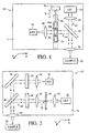
- laser diode 14 is shown providing a beam of a first wavelength ⁇ st1 .
- This exciting or stimulating beam is preferably passed through collimating lens 16 and then passes through beam splitter 18.
- the stimulating beam of wavelength ⁇ st1 passes through objective 22 and is focused onto a spot of sample 20 to cause signal radiation to be returned from the sample.
- the signal radiation emitted from sample 20 is gathered by objective 22, which has a high numerical aperture, into an emission beam and is directed back toward beam splitter 18.
- Beam splitter 18 is an interference-type spectral beam splitter designed to pass light of a specific wavelength, for example the laser diode wavelength ⁇ st1 , and to reflect light of a lower or higher wavelength than ⁇ st1 .
- wavelength includes wavelength bands, as typical emission for certain applications occur over ranges rather than as discrete wavelengths.
- the beam representing the light or signal radiation emitted by the sample has a wavelength of ⁇ em and is reflected by beam splitter 18 toward a detection path.
- Filter changer assembly 24 is shown in the detection path of Fig. 1, as an example of a filter system useful for isolation of emission.
- Filter changer assembly 24 contains three filters 26a-c. At least one of these filters isolates a beam of a wavelength ⁇ em , particularly ⁇ em/p , which is lower or shorter than ⁇ st1 , and at least one of these filters isolates a beam of wavelength ⁇ em , particularly ⁇ em/f , which is higher or longer than wavelength ⁇ st1 .
- the filter changer assembly may be moved by a shifting means 70, as shown by arrow A. This allows the correct filter to be placed in the path of the emission beam.
- Fig. 3 shows a means for shifting each of the filters within a slot 68 in support wall 60 of the scan head.
- the means for shifting 70 may be an actuator driven by a motor.
- the filter changer assembly 24 may have a plurality of filters in some other configuration, e.g. the filters may be mounted on a wheel and preferably rotated by a motor.
- the filtered emission are then passed through focusing lens 28 and onto the detector 30.
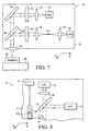
- the detector may be mounted on the scan head, as shown by detector 30 of Fig. 1, or it may be positioned remotely, as shown in Fig. 5. In this latter case, the focusing lens 28 focuses the emission beam into an optical fiber 58 which transmits the emission beam to the remotely positioned detector 56.
- the laser diode or other compact laser device may be of any of a variety of colors and wavelengths.
- infrared and red laser diodes are available.
- the laser may also be a compact, solid state, frequency-doubled diode or frequency-doubled diode pumped YAG laser.
- the use of a red laser diode is particularly useful, as it provides a stimulating beam having a wavelength ⁇ st1 of approximately 635 nm. Stimulation of the sample with light of this wavelength may cause fluorescence emission of a higher wavelength, e.g. 650 to 700 nm, and emission from a storage phosphor screen at a lower wavelength, e.g. approximately 390 nm.
- beam splitter 18 passes light of 635 nm but reflects both lower and higher numbers or shorter and longer wavelengths. "Approximately,” as used here, indicates a value within ⁇ 10% of the given value.
- the first side 11 of scan head 10 thus shows a first data channel, capable of reading storage phosphor screens by stimulating with wavelength ⁇ st1 and detecting emission through use of the appropriate filter in the detection path, and a second data channel, capable of reading fluorescent emission by stimulating with wavelength ⁇ st1 and detecting emission through use of the appropriate filter in the detection path.
- the first channel detects emission of wavelength ⁇ em/p where ⁇ em/p ⁇ ⁇ st1 .
- the second channel detects emission of wavelength ⁇ em/f where ⁇ em/f > ⁇ st1 .
- Collection and detection of transmitted and reflected signals resulting from laser diode stimulation may also be achieved, as through transmission collection and detection device 78, shown in Fig. 7, or through other well-known detection paths.
- Compact scan head 10 may be moved across a sample in two dimensions, as seen by arrows X and Y, which represent perpendicular axes.
- scan head 10 may move in a first direction relative to sample 20 and the sample may be moved in a perpendicular direction as by a motorized stage, or the scanning may occur according to some other scan pattern.
- the scan head may be moved by sliding it along a rail with a belt and pulley, lead screw, or other actuating means.
- Fig. 4 shows a means for moving 76 the scan head. Scanning is preferably accomplished in a point-by-point imaging manner wherein a plurality of spots of the sample are sequentially subjected to stimulation and detection of resulting emission.
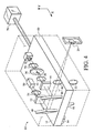
- Fig. 2 shows a second side 12 of scan head 10 of the present invention.
- the second side supports an LED point scanning system, such as that disclosed in commonly assigned patent application U.S. Serial No. 08/438,416.
- LED 32 provides a stimulating beam of a second wavelength ⁇ st2 which is focused by focusing lens 34 into the pinhole aperture 38 of spatial filter 36. This effectively restricts the diameter of the stimulating beam and defines the necessary resolution for stimulation.
- the stimulating beam of wavelength ⁇ st2 thus functions as a point light source. This is an important advantage as an LED is an incoherent light source and restriction of this nature allows for high resolution scanning.
- an optical fiber may provide the necessary restriction of the stimulation beam.
- Fig. 7 shows this alternate embodiment wherein an optical fiber 66 replaces spatial filter 36; focusing lens 34 then serves to focus the stimulating beam of wavelength ⁇ st2 into optical fiber 66.
- the focal points of lenses 34 and 42 are also spaced apart with fiber 66 between them.
- Fig. 7 also shows a transmitted light collector and detector 78. This transmission system 78, although shown in the Fig. 7 embodiment for clarity, may be used with any of the light sources on either side of the scan head.
- the restricted stimulating beam is collected by collimating lens 42 and passed through a filter 44 and then directed onto the sample.
- Fig. 2 shows a beam splitter 46 reflecting the stimulating beam and directing it toward objective 40 where it is focused onto a spot of sample 20.
- Light emitted or returned from the sample for example fluorescent or reflective signal radiation, is then collected by objective 40 and passes through beam splitter 46 to be directed toward the detection path of this third data channel.
- An appropriate beam splitter for fluorescent or reflective emission may be used.
- the emission returned from the sample are reflected by mirror 48 in Fig. 2 and directed through a second filter 52 and then through a second focusing lens 54. Focusing lens 54 serves to focus the beam onto detector 50.
- Focusing lens 54 serves to focus the beam onto detector 50.
- the detector may be mounted on the scan head 10 or it may be positioned remotely and connected to the scan head via an optical fiber.
- Fig. 6 shows this detector placement alternative, with focusing lens 54 serving to focus the returned emission into optical fiber 64 for transmission to detector 62, which is off scan head 10.
- LED point scanning system As disclosed in U.S. Serial No. 08/438,416, other variations of the LED point scanning system are possible on this second side of the compact scan head of the present invention.
- the LED provides an inexpensive alternative to the laser diode and is particularly useful for certain specified wavelengths.
- a blue LED providing a stimulation beam of a wavelength centered at approximately 450 nm may advantageously be used to stimulate samples for chemi-fluorescence applications. Green, yellow, orange, red, and infrared LEDs are also available.
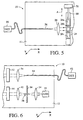
- Figs. 3 and 4 illustrate the described two sides of the scan head in perspective.
- Figs. 3 and 4 depict support wall 60, which is a preferred support within scan head 10, and serves as the support to which the optical elements of all configurations are mounted.
- the compact scan head of the present invention contains multiple scanning modalities which may or may not be coincident.
- two objectives 22 and 40 are visible.
- Objective 22 is part of the laser diode optical system on the first side 11 of the scan head
- objective 40 is part of the LED point scanning system of the second side 12 of the scan head.
- Support wall 60 completely separates all of the optical elements of the two sides of the scan head and, thus, the laser diode and the LED optical systems are separate.
- the first and second data channels share a laser diode, a collimating lens, beam splitter, and a detector, among other optical elements, however, and so, these modalities are at least partially coincident.
- the sample may be mounted relative to the scan head so that scanning by either side, and thus either optical configuration, or according to any of the three channels of the scan head, is possible. This is facilitated by the movable scan head and its preferred two-dimensional translation relative to the sample.
- Fig. 8 shows an alternate embodiment of the scan head, with multiple stimulating beams.
- a second laser diode 15 is shown on the first side 11 of the scan head.
- Laser diode 15 provides a stimulating beam which may be included in the stimulation optical path of the first side of the scan head via beam splitter 17.
- This second source may provide a different stimulating wavelength than the first source.
- the second source may provide a different optical property than the first source.
- the two sources may provide pulsed and continuous wave beams, or polarized and nonpolarized beams.
- a plurality of light sources may be used on the first side of the scan head. Stimulation preferably occurs in a sequential manner.
- the second side of the scan head may also have more than one light source.
- a second LED with an affiliated beam restriction means may be inserted into the optical path of the second side of the scan head, for example.
- These multiple sources on the second side may also provide unique wavelengths or other properties.
- the various channels on opposite sides of the scan head may also utilize beams of different optical properties, in general, rather than simply utilizing different wavelengths for stimulation.
- optical fiber delivery via optical fiber 67, from remotely positioned LED 33 to the scan head is shown.
- LED 33 provides a stimulating beam which is focused by lens 35 into fiber 67.
- Fiber 67 serves as both a delivery means and a restriction means.
- the restricted beam is received by lens 42, as before, and directed toward the sample.
- the laser diode stimulating beam of the first side may also be delivered from a remotely positioned source to the scan head through the use of an optical fiber.
- a combined detector may be used for the various channels and systems.
- a single detector may be particularly convenient when positioned remotely and connected to relevant locations within the scan head 10 by optical fibers.
- An array-type detector may also be used for the various channels.
- a spatial filter may be added to the detection path of the laser diode or LED optical systems, limiting the signals reaching the detector and, in certain cases, creating confocal systems.
- Each of the three channels, 81, 82, and 83 of Fig. 10, provides data regarding emission within the channel. These data are collected from the various detectors by a data analysis or processing means 72, such as a computer, and displayed, such as on a multi-channel data display 74, or saved in a memory for future analysis.
- the video monitor, or other display may display data from any or all of the three channels. Multi-channel displays are known in the art.
- the data analysis means may be programmed to operate the channels sequentially on the sample or to direct operation of the appropriate channel according to the nature of the sample.
- the particular dimensions of a storage phosphor screen or of a microtiter plate may cause first or third data channel stimulation and detection of emission to occur, the fitting of the sample holder onto the stage triggering the appropriate channel. Simultaneous reading of a sample according to more than one channel may also occur.
- the compactness of the scan head allows for high speed scanning and its optical systems allow for high resolution scanning.
- the scan head of the present invention provides versatility with regard to sample formats and types of optical analysis, thus contributing to reduced laboratory operating costs.
Landscapes
- Physics & Mathematics (AREA)
- Spectroscopy & Molecular Physics (AREA)
- General Physics & Mathematics (AREA)
- Health & Medical Sciences (AREA)
- Analytical Chemistry (AREA)
- Nuclear Medicine, Radiotherapy & Molecular Imaging (AREA)
- Life Sciences & Earth Sciences (AREA)
- Chemical & Material Sciences (AREA)
- Optics & Photonics (AREA)
- Biochemistry (AREA)
- General Health & Medical Sciences (AREA)
- Immunology (AREA)
- Pathology (AREA)
- Investigating, Analyzing Materials By Fluorescence Or Luminescence (AREA)
- Investigating Materials By The Use Of Optical Means Adapted For Particular Applications (AREA)
- Investigating Or Analysing Materials By The Use Of Chemical Reactions (AREA)
- Investigating Or Analysing Materials By Optical Means (AREA)
Description
Claims (12)
- A movable scan head optically coupled to stimulation and detection means (14, 32, 30, 50) for a plurality of the group comprising phosphorescence, fluorescence, reflection, and transmission for analyzing a sample, the scan head (10) comprising:characterized in that(a) first channel means (81) for stimulating the sample (20) with a beam of a first wavelength and detecting resultant storage phosphor emission from the sample,(b) second channel means (82) for stimulating the sample (20) with a beam of the first wavelength and detecting resultant fluorescent emission from the sample, wherein the first channel means (81) and second channel means (82) have common portions of their respective optical paths, and filter means (24) for distinguishing emissions from the sample corresponding to the first and second channel means,(c) third channel means (83) for stimulating the sample (20) with a beam of a second wavelength and detecting resultant second wavelength-stimulated emission from the sample, and(d) means (76) for moving the scan head (10) relative to the sample (20) in a scan pattern,
the first and second channel means (81, 82) are positioned on a first side (11) of a support wall (60) of the scan head (10) and the third channel means (83) is positioned on the opposite side (12) of said support wall (60). - The scan head of claim 1 further comprising:means (74) for displaying the information regarding emission from any of the first, second and third channel means.
- The scan head of claim 1 wherein the first and second channel means (81, 82) include a compact, lightweight laser device (14).
- The scan head of claim 3 wherein the first and second channel means (81, 82) include a laser diode (14).
- The scan head of claim 1 wherein the first and second channel means (81, 82) include a beam splitter (18) for passing the first wavelength stimulating beam and for reflecting emission received from the sample which is of a wavelength lower than or higher than the first wavelength.
- The scan head of claim 5 wherein the first and second channel means (81, 82) include a filter changer assembly (24) disposed to receive emission reflected by the beam splitter (18), the filter changer assembly (24) having at least one filter (26a; 26b; 26c) for passing emission received from the sample (20) which is of a wavelength lower than the first wavelength and at least one filter (26a; 26b; 26c) for passing emission received from the sample (20) which is of a wavelength higher than the first wavelength, and having means (70) for shifting each of the filters into the first and second channel means.
- The scan head of claim 1 wherein the third channel means (83) includes an LED (32).
- The scan head of claim 1 wherein the third channel means (83) includes a spatial filter (36) having a pinhole aperture (38) and a means (34) for focusing the second wavelength stimulating beam into the pinhole aperture (38) for restriction of the diameter of the second wavelength stimulating beam to a point light source for stimulation of the sample (20).
- The scan head of claim 1 wherein the third channel means (83) includes an optical fiber (66; 67) and a means (34; 35) for focusing the second wavelength stimulating beam into the optical fiber for restriction of the diameter of the second wavelength stimulating beam to a point light source for stimulation of the sample (20).
- The scan head of claim 1 wherein the detection means (72) directs operation of the first, second and third channel means sequentially on the sample (20).
- The scan head of claim 1 further comprising:wherein the detection means (72) for collecting information regarding emission from the first, second and third channel means collects information regarding emission from the fourth channel means.a fourth channel means for stimulating the sample (20) with a beam of a third wavelength and detecting resultant third wavelength stimulated emission from the sample (20),
- The scan head of claim 1 further comprising:wherein the detection means (72) for collecting information regarding emission from the first, second and third channel means collects information regarding emission from the fifth channel means.a fifth channel means for stimulating light with a beam of a fourth wavelength and detecting resultant fourth wavelength stimulated emission from the sample (20),
Applications Claiming Priority (3)
| Application Number | Priority Date | Filing Date | Title |
|---|---|---|---|
| US08/508,342 US5528050A (en) | 1995-07-24 | 1995-07-24 | Compact scan head with multiple scanning modalities |
| US508342 | 1995-07-24 | ||
| PCT/US1996/006370 WO1997004354A1 (en) | 1995-07-24 | 1996-05-06 | Compact scan head with multiple scanning modalities |
Publications (3)
| Publication Number | Publication Date |
|---|---|
| EP0792475A1 EP0792475A1 (en) | 1997-09-03 |
| EP0792475A4 EP0792475A4 (en) | 1999-09-22 |
| EP0792475B1 true EP0792475B1 (en) | 2003-09-03 |
Family
ID=24022365
Family Applications (1)
| Application Number | Title | Priority Date | Filing Date |
|---|---|---|---|
| EP96915535A Expired - Lifetime EP0792475B1 (en) | 1995-07-24 | 1996-05-06 | Compact scan head with multiple scanning modalities |
Country Status (5)
| Country | Link |
|---|---|
| US (1) | US5528050A (en) |
| EP (1) | EP0792475B1 (en) |
| JP (1) | JP4141512B2 (en) |
| DE (1) | DE69629794T2 (en) |
| WO (1) | WO1997004354A1 (en) |
Families Citing this family (80)
| Publication number | Priority date | Publication date | Assignee | Title |
|---|---|---|---|---|
| US5631734A (en) | 1994-02-10 | 1997-05-20 | Affymetrix, Inc. | Method and apparatus for detection of fluorescently labeled materials |
| US6068753A (en) * | 1996-05-06 | 2000-05-30 | Helena Laboratories Corporation | Automatic electrophoresis apparatus with fluorescent and visible scanning |
| JPH103134A (en) * | 1996-06-18 | 1998-01-06 | Fuji Photo Film Co Ltd | Image reader |
| EP0814594B1 (en) * | 1996-06-18 | 2004-09-08 | Fuji Photo Film Co., Ltd. | Image reading apparatus |
| US5780857A (en) * | 1996-10-04 | 1998-07-14 | Wallac Oy | Apparatus for imaging biochemical samples on substrates |
| JPH10213865A (en) * | 1997-01-30 | 1998-08-11 | Fuji Photo Film Co Ltd | Picture reader |
| US6043506A (en) * | 1997-08-13 | 2000-03-28 | Bio-Rad Laboratories, Inc. | Multi parameter scanner |
| US6051835A (en) * | 1998-01-07 | 2000-04-18 | Bio-Rad Laboratories, Inc. | Spectral imaging apparatus and methodology |
| US6201639B1 (en) | 1998-03-20 | 2001-03-13 | James W. Overbeck | Wide field of view and high speed scanning microscopy |
| US6185030B1 (en) | 1998-03-20 | 2001-02-06 | James W. Overbeck | Wide field of view and high speed scanning microscopy |
| AU5223899A (en) * | 1998-07-27 | 2000-02-21 | Ljl Biosystems, Inc. | Apparatus and methods for spectroscopic measurements |
| US6236456B1 (en) | 1998-08-18 | 2001-05-22 | Molecular Devices Corporation | Optical system for a scanning fluorometer |
| WO2000033136A1 (en) | 1998-11-25 | 2000-06-08 | Phormax Corporation | Portable device for scanning radiation storage screens |
| JP2000304698A (en) * | 1999-04-16 | 2000-11-02 | Canon Inc | Fluorescence measurement method and apparatus and substrate suitable therefor |
| WO2000068671A2 (en) * | 1999-05-12 | 2000-11-16 | Aclara Biosciences, Inc. | Multiplexed fluorescent detection in microfluidic devices |
| US6407395B1 (en) | 2000-02-29 | 2002-06-18 | The University Of Chicago | Portable biochip scanner device |
| US6329661B1 (en) | 2000-02-29 | 2001-12-11 | The University Of Chicago | Biochip scanner device |
| US6555838B1 (en) * | 2000-06-29 | 2003-04-29 | Essex Electro Engineering, Inc. | Method and apparatus for radiographic imaging |
| US6696698B2 (en) | 2000-06-29 | 2004-02-24 | Essex Electro Engineers, Inc. | Method and apparatus for radiographic imaging |
| US20040021101A1 (en) * | 2000-06-29 | 2004-02-05 | Essex Electro Engineers, Inc. | Method and apparatus for radiographic imaging |
| US20030160957A1 (en) * | 2000-07-14 | 2003-08-28 | Applera Corporation | Scanning system and method for scanning a plurality of samples |
| US6789040B2 (en) | 2000-08-22 | 2004-09-07 | Affymetrix, Inc. | System, method, and computer software product for specifying a scanning area of a substrate |
| US6800870B2 (en) * | 2000-12-20 | 2004-10-05 | Michel Sayag | Light stimulating and collecting methods and apparatus for storage-phosphor image plates |
| US6650411B2 (en) | 2001-04-26 | 2003-11-18 | Affymetrix, Inc. | System, method, and product for pixel clocking in scanning of biological materials |
| US6490533B2 (en) * | 2001-04-26 | 2002-12-03 | Affymetrix, Inc. | System, method, and product for dynamic noise reduction in scanning of biological materials |
| US6643015B2 (en) | 2001-04-26 | 2003-11-04 | Affymetrix, Inc. | System, method, and product for symmetrical filtering in scanning of biological materials |
| US7348587B2 (en) * | 2001-06-28 | 2008-03-25 | Fujifilm Corporation | Method for producing biochemical analysis data and apparatus used therefor |
| US6636292B2 (en) | 2001-09-05 | 2003-10-21 | Eastman Kodak Company | Printing apparatus for photosensitive media having a hybrid light source |
| JP3678192B2 (en) * | 2001-11-21 | 2005-08-03 | 横河電機株式会社 | Measuring device |
| EP1345026B1 (en) * | 2002-03-15 | 2010-05-05 | Affymetrix, Inc. | System and method for scanning of biological materials |
| US7148043B2 (en) | 2003-05-08 | 2006-12-12 | Bio-Rad Laboratories, Inc. | Systems and methods for fluorescence detection with a movable detection module |
| WO2004102627A2 (en) * | 2003-05-08 | 2004-11-25 | Alara, Inc. | Method and apparatus for radiation image erasure |
| US7317415B2 (en) | 2003-08-08 | 2008-01-08 | Affymetrix, Inc. | System, method, and product for scanning of biological materials employing dual analog integrators |
| US7295316B2 (en) * | 2004-01-14 | 2007-11-13 | Applera Corporation | Fluorescent detector with automatic changing filters |
| DE602005007582D1 (en) * | 2004-01-14 | 2008-07-31 | Applera Corp | IN BIOLOGICAL SAMPLES |
| US7277175B2 (en) * | 2004-09-21 | 2007-10-02 | Agilent Technologies, Inc. | Systems and methods for wavelength selective measurement of properties of small volume liquid samples |
| US8351026B2 (en) | 2005-04-22 | 2013-01-08 | Affymetrix, Inc. | Methods and devices for reading microarrays |
| US7329860B2 (en) * | 2005-11-23 | 2008-02-12 | Illumina, Inc. | Confocal imaging methods and apparatus |
| US8009889B2 (en) | 2006-06-27 | 2011-08-30 | Affymetrix, Inc. | Feature intensity reconstruction of biological probe array |
| US7813013B2 (en) * | 2006-11-21 | 2010-10-12 | Illumina, Inc. | Hexagonal site line scanning method and system |
| US7791013B2 (en) * | 2006-11-21 | 2010-09-07 | Illumina, Inc. | Biological microarray line scanning method and system |
| US8014577B2 (en) * | 2007-01-29 | 2011-09-06 | Institut National D'optique | Micro-array analysis system and method thereof |
| WO2008092226A1 (en) * | 2007-01-29 | 2008-08-07 | Institut National D'optique | Micro-array analysis system and method thereof |
| US8194240B1 (en) * | 2008-03-04 | 2012-06-05 | Kla-Tencor Corporation | Enhanced focusing capability on a sample using a spot matrix |
| US20090236541A1 (en) * | 2008-03-24 | 2009-09-24 | General Electric Company | System and Methods for Optical Imaging |
| EP2108991A1 (en) * | 2008-04-08 | 2009-10-14 | PerkinElmer Cellular Technologies Germany GmbH | Scanning Microscope |
| US9767342B2 (en) | 2009-05-22 | 2017-09-19 | Affymetrix, Inc. | Methods and devices for reading microarrays |
| JP5609533B2 (en) * | 2010-10-22 | 2014-10-22 | 富士ゼロックス株式会社 | Detection device, image forming device |
| JP5789724B2 (en) | 2011-12-16 | 2015-10-07 | リ−コール インコーポレーティッド | Luminescence imaging scanner |
| JP5575159B2 (en) * | 2012-01-26 | 2014-08-20 | シャープ株式会社 | Fluorescence information reading apparatus and fluorescence information reading method |
| WO2015031596A1 (en) | 2013-08-28 | 2015-03-05 | Illumina, Inc. | Optical alignment tool |
| US10540783B2 (en) * | 2013-11-01 | 2020-01-21 | Illumina, Inc. | Image analysis useful for patterned objects |
| ES2876432T3 (en) | 2014-05-16 | 2021-11-12 | Illumina Inc | Nucleic acid synthesis techniques |
| KR20170066540A (en) | 2014-10-09 | 2017-06-14 | 일루미나, 인코포레이티드 | Method and device for separating immiscible liquids to effectively isolate at least one of the liquids |
| GB201701689D0 (en) | 2017-02-01 | 2017-03-15 | Illumia Inc | System and method with fiducials of non-closed shapes |
| US11896944B2 (en) | 2017-02-01 | 2024-02-13 | Illumina, Inc. | System and method with fiducials responding to multiple excitation frequencies |
| GB201701686D0 (en) | 2017-02-01 | 2017-03-15 | Illunina Inc | System & method with fiducials having offset layouts |
| GB201701688D0 (en) * | 2017-02-01 | 2017-03-15 | Illumia Inc | System and method with fiducials in non-recliner layouts |
| GB201701691D0 (en) | 2017-02-01 | 2017-03-15 | Illumina Inc | System and method with reflective fiducials |
| EP4462437A3 (en) | 2017-03-30 | 2025-03-26 | Illumina, Inc. | Genomic data analysis system and method |
| NL2023310B1 (en) | 2019-03-21 | 2020-09-28 | Illumina Inc | Training data generation for artificial intelligence-based sequencing |
| NL2023314B1 (en) | 2019-03-21 | 2020-09-28 | Illumina Inc | Artificial intelligence-based quality scoring |
| US11210554B2 (en) | 2019-03-21 | 2021-12-28 | Illumina, Inc. | Artificial intelligence-based generation of sequencing metadata |
| NL2023311B9 (en) | 2019-03-21 | 2021-03-12 | Illumina Inc | Artificial intelligence-based generation of sequencing metadata |
| NL2023316B1 (en) | 2019-03-21 | 2020-09-28 | Illumina Inc | Artificial intelligence-based sequencing |
| WO2020191389A1 (en) | 2019-03-21 | 2020-09-24 | Illumina, Inc. | Training data generation for artificial intelligence-based sequencing |
| NL2023312B1 (en) | 2019-03-21 | 2020-09-28 | Illumina Inc | Artificial intelligence-based base calling |
| US12354008B2 (en) | 2020-02-20 | 2025-07-08 | Illumina, Inc. | Knowledge distillation and gradient pruning-based compression of artificial intelligence-based base caller |
| US11188778B1 (en) | 2020-05-05 | 2021-11-30 | Illumina, Inc. | Equalization-based image processing and spatial crosstalk attenuator |
| WO2022271689A1 (en) | 2021-06-25 | 2022-12-29 | Illumina, Inc. | Fiducials for use in registration of a patterned surface |
| AU2022296802A1 (en) | 2021-06-25 | 2024-01-04 | Illumina, Inc. | Linear fourier fiducial |
| WO2023003757A1 (en) | 2021-07-19 | 2023-01-26 | Illumina Software, Inc. | Intensity extraction with interpolation and adaptation for base calling |
| US11455487B1 (en) | 2021-10-26 | 2022-09-27 | Illumina Software, Inc. | Intensity extraction and crosstalk attenuation using interpolation and adaptation for base calling |
| CN115753698A (en) * | 2021-09-02 | 2023-03-07 | 安徽皖仪科技股份有限公司 | An optical system for PCR fluorescence detection scanning head |
| US12566125B2 (en) | 2021-09-10 | 2026-03-03 | Illumina, Inc. | Sequencer focus quality metrics and focus tracking for periodically patterned surfaces |
| WO2023049215A1 (en) | 2021-09-22 | 2023-03-30 | Illumina, Inc. | Compressed state-based base calling |
| US20230343414A1 (en) | 2022-03-25 | 2023-10-26 | Illumina, Inc. | Sequence-to-sequence base calling |
| JP2025526537A (en) | 2022-06-09 | 2025-08-15 | イルミナ インコーポレイテッド | Dependence of base calling on flow cell tilt |
| US20240033738A1 (en) | 2022-07-27 | 2024-02-01 | Illumina, Inc. | Flow cell based motion system calibration and control methods |
| WO2024072799A1 (en) | 2022-09-26 | 2024-04-04 | Illumina, Inc. | Flow cell based motion system calibration and control methods |
Family Cites Families (12)
| Publication number | Priority date | Publication date | Assignee | Title |
|---|---|---|---|---|
| US4019060A (en) * | 1975-10-03 | 1977-04-19 | Gte Sylvania Incorporated | Fluorescence locating system and method |
| US5202744A (en) * | 1988-07-29 | 1993-04-13 | Louis Thomas A | Electro-optical measuring instruments |
| US4972258A (en) * | 1989-07-31 | 1990-11-20 | E. I. Du Pont De Nemours And Company | Scanning laser microscope system and methods of use |
| EP0418928B1 (en) * | 1989-09-22 | 1996-05-01 | Fuji Photo Film Co., Ltd. | Scanning microscope and scanning mechanism for the same |
| US5386112A (en) * | 1990-06-29 | 1995-01-31 | Dixon; Arthur E. | Apparatus and method for transmitted-light and reflected-light imaging |
| GB9015793D0 (en) * | 1990-07-18 | 1990-09-05 | Medical Res Council | Confocal scanning optical microscope |
| US5266803A (en) * | 1991-03-03 | 1993-11-30 | Bio-Rad Labratories, Inc. | Fiber optic storage phosphor imaging plate scanner |
| JPH04348258A (en) * | 1991-05-27 | 1992-12-03 | Kowa Co | Multi-channel optical measuring device |
| US5343224A (en) * | 1992-09-22 | 1994-08-30 | Xerox Corporation | Diode laser multiple output scanning system |
| US5325381A (en) * | 1992-12-22 | 1994-06-28 | Xerox Corporation | Multiple beam diode laser output scanning system |
| US5325383A (en) * | 1993-05-17 | 1994-06-28 | Eastman Kodak Company | Laser diode operated in hybrid modulation modes |
| US5436718A (en) * | 1993-07-30 | 1995-07-25 | Biolumin Corporation | Mutli-functional photometer with movable linkage for routing optical fibers |
-
1995
- 1995-07-24 US US08/508,342 patent/US5528050A/en not_active Expired - Lifetime
-
1996
- 1996-05-06 WO PCT/US1996/006370 patent/WO1997004354A1/en not_active Ceased
- 1996-05-06 DE DE69629794T patent/DE69629794T2/en not_active Expired - Lifetime
- 1996-05-06 EP EP96915535A patent/EP0792475B1/en not_active Expired - Lifetime
- 1996-07-23 JP JP19356996A patent/JP4141512B2/en not_active Expired - Fee Related
Also Published As
| Publication number | Publication date |
|---|---|
| WO1997004354A1 (en) | 1997-02-06 |
| US5528050A (en) | 1996-06-18 |
| EP0792475A1 (en) | 1997-09-03 |
| DE69629794T2 (en) | 2004-08-05 |
| EP0792475A4 (en) | 1999-09-22 |
| DE69629794D1 (en) | 2003-10-09 |
| JP4141512B2 (en) | 2008-08-27 |
| JPH0954035A (en) | 1997-02-25 |
Similar Documents
| Publication | Publication Date | Title |
|---|---|---|
| US5528050A (en) | Compact scan head with multiple scanning modalities | |
| US5578818A (en) | LED point scanning system | |
| US6750457B2 (en) | System for high throughput analysis | |
| US6355934B1 (en) | Imaging system for an optical scanner | |
| US7782454B2 (en) | Universal multidetection system for microplates | |
| US11029506B2 (en) | Scanning microscope with multiplexed light sources | |
| EP1580586B1 (en) | Scanning confocal microscope | |
| US6683735B2 (en) | Rapidly changing dichroic beamsplitter in epifluorescent microscopes | |
| US8357281B2 (en) | Multi-wavelength fluorescence detection system for multiplexed capillary electrophoresis | |
| US20100314554A1 (en) | Device to illuminate an object with a multispectral light source and detect the spectrum of the emitted light | |
| US20060158721A1 (en) | Confocal microscope | |
| JP2009517662A (en) | Confocal imaging method and apparatus | |
| JPH10504916A5 (en) | ||
| CA2461499A1 (en) | Imaging of microarrays using fiber optic exciter | |
| US20050146784A1 (en) | Confocal microscope having multiple independent excitation paths | |
| EP1157268A1 (en) | Imaging system for an optical scanner | |
| JP2907571B2 (en) | Laser scanning fluorescence microscope | |
| US20260056164A1 (en) | Dual Mode Scanning Optical System for Capillary Electrophoresis | |
| JPH10227694A (en) | Luminescence identifying apparatus |
Legal Events
| Date | Code | Title | Description |
|---|---|---|---|
| PUAI | Public reference made under article 153(3) epc to a published international application that has entered the european phase |
Free format text: ORIGINAL CODE: 0009012 |
|
| 17P | Request for examination filed |
Effective date: 19970417 |
|
| AK | Designated contracting states |
Kind code of ref document: A1 Designated state(s): CH DE FR GB LI |
|
| A4 | Supplementary search report drawn up and despatched |
Effective date: 19990805 |
|
| AK | Designated contracting states |
Kind code of ref document: A4 Designated state(s): CH DE FR GB LI |
|
| RIC1 | Information provided on ipc code assigned before grant |
Free format text: 6G 03B 42/00 A, 6G 02B 21/00 B, 6G 01N 21/64 B |
|
| 17Q | First examination report despatched |
Effective date: 20010313 |
|
| GRAH | Despatch of communication of intention to grant a patent |
Free format text: ORIGINAL CODE: EPIDOS IGRA |
|
| RAP1 | Party data changed (applicant data changed or rights of an application transferred) |
Owner name: AMERSHAM BIOSCIENCES SV CORP. |
|
| RAP1 | Party data changed (applicant data changed or rights of an application transferred) |
Owner name: AMERSHAM BIOSCIENCES (SV) CORP. |
|
| GRAS | Grant fee paid |
Free format text: ORIGINAL CODE: EPIDOSNIGR3 |
|
| GRAA | (expected) grant |
Free format text: ORIGINAL CODE: 0009210 |
|
| AK | Designated contracting states |
Kind code of ref document: B1 Designated state(s): CH DE FR GB LI |
|
| REG | Reference to a national code |
Ref country code: GB Ref legal event code: FG4D |
|
| REG | Reference to a national code |
Ref country code: CH Ref legal event code: EP |
|
| REF | Corresponds to: |
Ref document number: 69629794 Country of ref document: DE Date of ref document: 20031009 Kind code of ref document: P |
|
| REG | Reference to a national code |
Ref country code: CH Ref legal event code: NV Representative=s name: PATENTANWAELTE BREITER + WIEDMER AG |
|
| ET | Fr: translation filed | ||
| PLBE | No opposition filed within time limit |
Free format text: ORIGINAL CODE: 0009261 |
|
| STAA | Information on the status of an ep patent application or granted ep patent |
Free format text: STATUS: NO OPPOSITION FILED WITHIN TIME LIMIT |
|
| 26N | No opposition filed |
Effective date: 20040604 |
|
| REG | Reference to a national code |
Ref country code: CH Ref legal event code: PFA Owner name: GE HEALTHCARE (SV) CORP. Free format text: AMERSHAM BIOSCIENCES (SV) CORP.#928 EAST ARQUES AVENUE#SUNNYVALE, CA 94086-4520 (US) -TRANSFER TO- GE HEALTHCARE (SV) CORP.#800 CENTENNIAL AVENUE#PISCATAWAY, NJ 08855 (US) Ref country code: CH Ref legal event code: NV Representative=s name: BREITER + PARTNER AG PATENT - UND MARKENBUERO |
|
| REG | Reference to a national code |
Ref country code: FR Ref legal event code: CD |
|
| REG | Reference to a national code |
Ref country code: CH Ref legal event code: PFA Owner name: GE HEALTHCARE (SV) CORP. Free format text: GE HEALTHCARE (SV) CORP.#800 CENTENNIAL AVENUE#PISCATAWAY, NJ 08855 (US) -TRANSFER TO- GE HEALTHCARE (SV) CORP.#800 CENTENNIAL AVENUE#PISCATAWAY, NJ 08855 (US) |
|
| REG | Reference to a national code |
Ref country code: CH Ref legal event code: PUE Owner name: GE HEALTHCARE BIO-SCIENCES CORP. Free format text: GE HEALTHCARE (SV) CORP.#800 CENTENNIAL AVENUE#PISCATAWAY, NJ 08855 (US) -TRANSFER TO- GE HEALTHCARE BIO-SCIENCES CORP.#800 CENTENNIAL AVENUE#PISCATAWAY, NJ 08855 (US) Ref country code: CH Ref legal event code: NV Representative=s name: ISLER & PEDRAZZINI AG |
|
| REG | Reference to a national code |
Ref country code: DE Ref legal event code: R082 Ref document number: 69629794 Country of ref document: DE Representative=s name: HEISSE KURSAWE EVERSHEDS RECHTSANWAELTE PATENT, DE |
|
| REG | Reference to a national code |
Ref country code: GB Ref legal event code: 732E Free format text: REGISTERED BETWEEN 20120614 AND 20120620 |
|
| REG | Reference to a national code |
Ref country code: DE Ref legal event code: R082 Ref document number: 69629794 Country of ref document: DE Representative=s name: HEISSE KURSAWE EVERSHEDS RECHTSANWAELTE PATENT, DE Effective date: 20120703 Ref country code: DE Ref legal event code: R081 Ref document number: 69629794 Country of ref document: DE Owner name: GE HEALTHCARE BIO-SCIENCES CORP., PISCATAWAY, US Free format text: FORMER OWNER: GE HEALTHCARE )SV) CORP.(N.D.GES.D.STAATES DELAWARE), SUNNYVALLE, CALIF., US Effective date: 20120703 Ref country code: DE Ref legal event code: R081 Ref document number: 69629794 Country of ref document: DE Owner name: GE HEALTHCARE BIO-SCIENCES CORP., US Free format text: FORMER OWNER: GE HEALTHCARE )SV) CORP.(N.D.GES.D.STAATES DELAWARE), SUNNYVALLE, US Effective date: 20120703 |
|
| REG | Reference to a national code |
Ref country code: FR Ref legal event code: TP Owner name: GE HEALTHCARE BIO-SCIENCES CORP., US Effective date: 20130128 |
|
| PGFP | Annual fee paid to national office [announced via postgrant information from national office to epo] |
Ref country code: GB Payment date: 20140527 Year of fee payment: 19 |
|
| PGFP | Annual fee paid to national office [announced via postgrant information from national office to epo] |
Ref country code: CH Payment date: 20140527 Year of fee payment: 19 Ref country code: FR Payment date: 20140519 Year of fee payment: 19 Ref country code: DE Payment date: 20140529 Year of fee payment: 19 |
|
| REG | Reference to a national code |
Ref country code: DE Ref legal event code: R119 Ref document number: 69629794 Country of ref document: DE |
|
| REG | Reference to a national code |
Ref country code: CH Ref legal event code: PL |
|
| GBPC | Gb: european patent ceased through non-payment of renewal fee |
Effective date: 20150506 |
|
| PG25 | Lapsed in a contracting state [announced via postgrant information from national office to epo] |
Ref country code: LI Free format text: LAPSE BECAUSE OF NON-PAYMENT OF DUE FEES Effective date: 20150531 Ref country code: CH Free format text: LAPSE BECAUSE OF NON-PAYMENT OF DUE FEES Effective date: 20150531 |
|
| REG | Reference to a national code |
Ref country code: FR Ref legal event code: ST Effective date: 20160129 |
|
| PG25 | Lapsed in a contracting state [announced via postgrant information from national office to epo] |
Ref country code: GB Free format text: LAPSE BECAUSE OF NON-PAYMENT OF DUE FEES Effective date: 20150506 Ref country code: DE Free format text: LAPSE BECAUSE OF NON-PAYMENT OF DUE FEES Effective date: 20151201 |
|
| PG25 | Lapsed in a contracting state [announced via postgrant information from national office to epo] |
Ref country code: FR Free format text: LAPSE BECAUSE OF NON-PAYMENT OF DUE FEES Effective date: 20150601 |