EP0792449B1 - Fluid sampler - Google Patents
Fluid sampler Download PDFInfo
- Publication number
- EP0792449B1 EP0792449B1 EP95943334A EP95943334A EP0792449B1 EP 0792449 B1 EP0792449 B1 EP 0792449B1 EP 95943334 A EP95943334 A EP 95943334A EP 95943334 A EP95943334 A EP 95943334A EP 0792449 B1 EP0792449 B1 EP 0792449B1
- Authority
- EP
- European Patent Office
- Prior art keywords
- passageway
- fluid
- casing
- rotary member
- detector
- Prior art date
- Legal status (The legal status is an assumption and is not a legal conclusion. Google has not performed a legal analysis and makes no representation as to the accuracy of the status listed.)
- Expired - Lifetime
Links
Images

Classifications
-
- G—PHYSICS
- G01—MEASURING; TESTING
- G01N—INVESTIGATING OR ANALYSING MATERIALS BY DETERMINING THEIR CHEMICAL OR PHYSICAL PROPERTIES
- G01N15/00—Investigating characteristics of particles; Investigating permeability, pore-volume or surface-area of porous materials
- G01N15/02—Investigating particle size or size distribution
- G01N15/0205—Investigating particle size or size distribution by optical means
- G01N15/0227—Investigating particle size or size distribution by optical means using imaging; using holography
-
- G—PHYSICS
- G01—MEASURING; TESTING
- G01N—INVESTIGATING OR ANALYSING MATERIALS BY DETERMINING THEIR CHEMICAL OR PHYSICAL PROPERTIES
- G01N15/00—Investigating characteristics of particles; Investigating permeability, pore-volume or surface-area of porous materials
- G01N15/02—Investigating particle size or size distribution
- G01N2015/0294—Particle shape
Definitions
- Determination of the quantity, size, characteristics, and types of particulate matter in fluids is important for many applications such as monitoring fluids in engines and rotating machinery, industrial quality control, food processing, medical analysis, and environmental control. For example, as an engine ages, it flakes metal particulates into its lubricating oil. It is known that the size, number, and shape of particulates correspond to engine condition, and can alert one to imminent engine failure. Predicting failure is critically important in aircraft engines, where sudden failure could result in a crash and loss of life. Heretofore, oil particulates were checked by extracting an oil sample while the aircraft is on the ground, and sending the oil to a laboratory for testing. Although necessary for safety, this process is time consuming.
- Copending U.S. patent application 08/143,370 (attorney docket no. 74,852) by Reintjes et al. discloses a system which optically images a fluid flow, detects the image, and classifies the size and shape of particulates in the fluid.
- that system images an entire fluid line, such as an oil line in an engine.
- the imaging system must have a large depth of view, which severely restricts the magnification by the optics between the pipe and the detector. With such a small magnification, that system cannot resolve extremely small particulates, for example 50 microns or smaller.
- an object of the invention is to permit monitoring of particulates in a fluid, in which the particulates are on the order of 50 microns or less.
- Another object is to do so by optically imaging a portion of the fluid.
- the passageway is sufficiently thin that the diffraction pattern of light exiting it is characteristic of the optical near field, the passageway will be very thin in most, if not all, practical applications, and have a corresponding small depth of view. This permits use of imaging optics having a much higher magnification than is possible with the invention of U.S. patent application 08/143,370, with a corresponding ability to image particulates as small as 10 microns or smaller.
- the system images only the passageway's near field, the system will image all opaque matter in the passageway clearly regardless of whether the opaque material is near the system's focal plane.
- this permits one to image, and detect, all opaque particulates in a fluid traveling through the passageway, not just those particulates in the vicinity of the optical focal plane, permitting an increase in the counting efficiency and statistical accuracy of the system.
- the system can process images continuously, quickly, and automatically in situ .
- This permits monitoring of particulates in a fluid flowing through the passageway in real time. If, for example, the fluid is engine oil, one can monitor number, shape, and size of particulates in the oil continuously, without needing to shut down the engine. This in turn permits early detection of engine failure, while simultaneously eliminating engine downtime which heretofore was needed to send samples of engine oil to a laboratory for examination.
- the present invention can, provide a more thorough analysis of wear and thereby introduce a quantum improvement in diagnostic capability.
- the present invention provides useful information by continuously sampling the engine oil and can provide a histogram indicating the distribution of particulate sizes, shapes, etc.
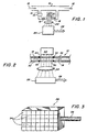
- figure 1 shows a pipe 10 which carries a fluid such as engine oil. A portion of the flow is tapped off continuously through line 14, aided as necessary by booster pump 16. Tapped fluid flows in direction 18 through a passageway 21 in line 14. Passageway 21 permits light (shown as dotted lines in figures 1 and 2) from laser 20 to pass through onto imaging optics 22. Imaging optics 22 projects a magnified image of the interior of passageway 21 onto planar detector 26. Member 22 can be any appropriate and known means for producing a magnified optical image, including simple or compound lenses, provided that it is capable of producing images of objects with the desired spatial resolution.
- the magnification is chosen in conjunction with the planar detector 26 to provide sufficient resolution to detect particulates of the order of 10 micrometers or smaller.
- Detector 26 is preferably a conventional planar array of light sensitive photodiodes or pototransistors, for transducing the image into corresponding electronic data.
- Cable 28 transmits this data to a processor, preferably a computer programmed to analyze the image, in a manner discussed further below.
- FIG. 2 The embodiment of figure 2 is similar to that of figure 1, in which passageway 21 is in the form of a pair of optical plates 23, 25 located between laser 20 and optics 22. Plates 23, 25 are bonded in a fluid tight manner at 30 to form a conduit for the fluid. Bonding can be done in any conventional manner, e.g. heat pressing or epoxying.
- Figure 3 illustrates a conventional photodetector array, such as could be used for detector 26 in figures 1 or 2.
- the array is a planar matrix of cells 34, each of which contains a light sensitive device, such as a photodiode or phototransistor. Presence of light triggers current output by the devices of pixels 34 in proportion to light intensity. Projection of an image onto pixels 34 thus causes the image to be converted to a plurality of current magnitudes, which when integrated provide a pixel-wise representation of the image in the form of charge magnitudes. In this manner, the image is converted to electronic data, which can be read out via data line 28 for processing.
- a light sensitive device such as a photodiode or phototransistor
- the duration of the pulses is chosen in accordance with the flow rate of fluid in line 14, so as to image as much of the fluid as possible, and thus improve the quality of statistical sampling of particle size and shape.
- the desired pulse repetition period is the time necessary for a complete fluid volume in the passageway to clear. If the laser illuminates only a fraction of passageway 21, the preferred repetition period is reduced by that fraction, etc.
- the width of passageway 21 in the direction of light travel is sufficiently small so that the diffraction pattern from the interior of passageway 21 represented by light exiting passageway 21 is characterized by the system's optical near field. Passageway 21's depth is determined by the depth of field necessary to sharply image particles of interest. For objects less than 50 microns across, passageway 21 should nominally be on the order of 200 to 250 microns wide.
- Laser 20 is preferably a commonplace laser diode, and is chosen to be of a frequency to which fluid in passageway 21 is effectively transparent.
- synthetic based oils commonly used in aircraft e.g. as specified by U.S. Department of Defense military lubricant specification MIL L 236997808
- human blood a laser radiating at 850 nm would be effective and otherwise appropriate.
- the embodiments of figures 1 and 2 are triggered by a timing clock (not shown) which causes laser 20 to discharge a pulse of coherent light through passageway 21, which is imaged onto detector array 26. Particulates in the fluid appear as dark shapes in the image. The same pulse (appropriately delayed to permit charging of the pixels in detector 26) also triggers array 26 to transmit its electronic version of the image to a computer (not shown) for processing. Repeatedly triggering the system in this manner builds up over time statistically useful information about the particulates in the fluid, despite the very small volume of fluid present in passageway 21 at any one time.
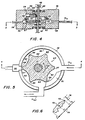
- Figures 4-5 illustrate an alternative scheme for imaging the fluid.
- Two members 36, 38 form a casing which defines therebetween a space 42 in fluid contact with input portion 14 in and output portion 14 out of line 14. Space 42 is separated from the remainder of the interior of casing 36, 38 by seals 60.
- Penetrating casing 36, 38 is shaft 46 of rotary member 40.
- Member 40 is made of material which is transparent to output of laser 54, and has a planar portion which is perpendicular to shaft 46 (best seen in figure 5) which contains a conical reflector 51 disposed symmetrically about shaft 46.
- Rotor 46 is mounted via bearings 50, 52 in casing 36, 38 for rotation (as indicate at 48) about the central axis of shaft 48.
- Penetrating casing member 36 is a laser (or optical transmission line for delivery of laser output) 54.
- Laser 54 is connected optically via optical glass 57 to mirror 59, which are mounted within member 36 to direct light 53 emitted from 54 to mirror 51 and thence to a combined optics package and detector 56, which performs the same function as optics 22 and detector 26 in the embodiments of figures 1-3 (and which for simplicity will be referred to as "detector package" 56).
- Data line 58 penetrates casing 36, 38 to relay data from detector package 56.
- the planar portion of member 40 has a plurality of scallops 62 circumferentially disposed about its periphery which define therebetween a corresponding of circumferentially disposed protrusions 66.
- portion 46 is asymmetrically located within opening 42, so that inner wall 39 of member 38 is increasingly closer to protrusions 56 as said protusions proceed from inlet 14 in to detector package 56, and then becomes increasingly distant up to outlet 14 out , and then closer again due to ridge 61 extending radially outwards from casing member 38.
- tapped fluid enters opening 42 via line 14 in which exposes it to rotary member 40 which is being rotated by an external motor (not shown).
- Scallops 62 scoop the fluid and carry it with rotary member 40 towards detector package 56. Because inner wall 39 of member 38 becomes increasingly near scallops 62 as member 40 moves towards detector package 56, the fluid becomes compacted, and sheared by protrusions 66. In this manner, the fluid is forced into a thin film 67 between detector package 56 and the protrusions 66 as they pass by.
- Pulsed light from laser 54 travels via mirrors 51, 59, and the optical glass constituting members 57 and 40, to gap 67 and thence to detector package 56, and via data output 58, to a computer (not shown) for processing.
- gap 67 is imaged in the same manner as passageway 21 of figures 1-2.
- fluid in scallops 62 move towards output 14 out where protrusions 66 cooperate with ridge 61 to force the fluid out of casing 36, 38.
- Figure 7 shows a method of identifying the sizes and shapes of particulates imaged in gap 67 or passageway 21. Taking the individual pixel data output from detectors 28 or 56, and preferably using a dedicated computer, one scans the image (86) sequentially pixel by pixel (e.g. row by row) until one locates a pixel (88) having a preselectedly low signal, indicating that an object shadowed light from the pixel during imaging. One then determines if this pixel has a "flag" on it (89) indicating that the pixel belongs to a group of pixels which constitute the image of an object which has already been encountered in the scan (89).
- Figure 6 shows a particulate such as one might find in used engine oil, jagged with a long dimension 74, and short dimension 76. Because its shape, i.e. periphery, would be recorded in chain code, by simple analytical geometry one can readily identify axes 74, 76, and their respective lengths. Their ratio is the object's aspect ratio, a measure of its thinness.
- Both aspect ratio and longest axis provide important information about, e.g., engine condition: long, thin, particulates can indicate excessive cutting wear; longest axis can indicate how far engine wear has progressed (with sheading of larger particulates expected nearer to engine failure).
Landscapes
- Chemical & Material Sciences (AREA)
- Dispersion Chemistry (AREA)
- Physics & Mathematics (AREA)
- Health & Medical Sciences (AREA)
- Life Sciences & Earth Sciences (AREA)
- Analytical Chemistry (AREA)
- Biochemistry (AREA)
- General Health & Medical Sciences (AREA)
- General Physics & Mathematics (AREA)
- Immunology (AREA)
- Pathology (AREA)
- Investigating Or Analysing Materials By Optical Means (AREA)
- Sampling And Sample Adjustment (AREA)
Abstract
Description
Claims (3)
- A particle classifier comprising :wherein the width of said passageway in said direction transverse to said passageway is selected to be of a size which causes the diffraction pattern formed of the interior of said passageway by said light passing through said passageway to be of the optical near field of said interior ;means for diverting fluid from a flow line into a passageway ;a source of coherent light ;optical means, responsive to coherent light from said source, for periodically imaging said fluid in said passageway onto an optical detector, said detector being effective to transduce said image into electronic pixel information ;
said classifier further comprising an analysis means for classifying, responsive to said electronic pixel information, the distribution of sizes or shapes of objects in said image. - A method of particle classification comprising :diverting fluid from a flow line into a passageway;providing a source of coherent light ;responsive to coherent light from said source, periodically imaging said fluid in said passageway onto an optical detector, said detector being effective to transduce said image into electronic pixel information ;selecting the width of said passageway in said direction transverse to said passageway to be of a size which causes the diffraction pattern formed of the interior of said passageway by said light passing through said passageway to be of the optical near field of said interior ;classifying, responsive to said electronic pixel information, the distribution of sizes or shapes of objects in said image.
- An apparatus comprising :wherein said rotary member has a plurality of scallops disposed about the circumference of said rotary member in said plane to form a corresponding plurality of concave depressions for receiving fluid in said casing, and to form between said scallops a plurality of protrusions ;a casing defining a space and having a fluid inlet and a fluid outlet ;an optical detector adjacent to the space ;a rotary member disposed for rotation in a plane in said casing about an axis transverse to said plane ;means for rotating said rotary member in said plane about said axis ;
wherein said axis is disposed asymmetrically within said casing so that the inner wall of said casing is increasingly closer to said protrusions as said protrusions proceed from said inlet to said detector in the direction of said rotation of said rotary member ;
wherein said casing comprises a source of light disposed effective to radiate coherent light towards said rotary member in said plane ; and
wherein the distance between said detector and a current protrusion facing the detector constitutes an imaging gap, said imaging gap being selected to be of a size to cause the diffraction pattern formed by said light passing through said imaging gap to be of said gap's optical near field.
Applications Claiming Priority (3)
| Application Number | Priority Date | Filing Date | Title |
|---|---|---|---|
| US342053 | 1994-11-17 | ||
| US08/342,053 US5572320A (en) | 1994-11-17 | 1994-11-17 | Fluid sampler utilizing optical near-field imaging |
| PCT/US1995/015110 WO1996016325A1 (en) | 1994-11-17 | 1995-11-17 | Fluid sampler |
Publications (3)
| Publication Number | Publication Date |
|---|---|
| EP0792449A1 EP0792449A1 (en) | 1997-09-03 |
| EP0792449A4 EP0792449A4 (en) | 1999-02-24 |
| EP0792449B1 true EP0792449B1 (en) | 2005-05-11 |
Family
ID=23340133
Family Applications (1)
| Application Number | Title | Priority Date | Filing Date |
|---|---|---|---|
| EP95943334A Expired - Lifetime EP0792449B1 (en) | 1994-11-17 | 1995-11-17 | Fluid sampler |
Country Status (7)
| Country | Link |
|---|---|
| US (1) | US5572320A (en) |
| EP (1) | EP0792449B1 (en) |
| JP (1) | JP3571348B2 (en) |
| AT (1) | ATE295534T1 (en) |
| DE (1) | DE69534204T2 (en) |
| FI (1) | FI117065B (en) |
| WO (1) | WO1996016325A1 (en) |
Cited By (1)
| Publication number | Priority date | Publication date | Assignee | Title |
|---|---|---|---|---|
| US8236168B2 (en) | 2009-10-13 | 2012-08-07 | Exxonmobil Research And Engineering Company | Onset haze measurement apparatus and procedure |
Families Citing this family (39)
| Publication number | Priority date | Publication date | Assignee | Title |
|---|---|---|---|---|
| US6014204A (en) * | 1998-01-23 | 2000-01-11 | Providence Health System | Multiple diameter fiber optic device and process of using the same |
| JPH11242041A (en) * | 1998-02-26 | 1999-09-07 | Shimadzu Corp | Film inspection equipment |
| US6691557B1 (en) * | 2000-03-17 | 2004-02-17 | Norman Rice | Analysis method for liquid-filled electric equipment |
| US6928861B1 (en) | 2000-03-17 | 2005-08-16 | Norman Rice | Method for a reliability assessment, failure prediction and operating condition determination of electric equipment |
| NL1015640C2 (en) * | 2000-07-06 | 2002-01-08 | Univ Delft Tech | Device and method for determining the shape and / or size of small particles. |
| US6678052B1 (en) * | 2000-10-03 | 2004-01-13 | General Electric Company | On-line system for measuring properties of a product |
| US6966994B2 (en) * | 2001-04-17 | 2005-11-22 | Caterpillar Inc | Contamination control for engines |
| US20030209647A1 (en) * | 2002-05-09 | 2003-11-13 | Lockheed Martin Corporation | Temperature compensating optical debris analysis fixture |
| US7385694B2 (en) * | 2002-06-04 | 2008-06-10 | Lockheed Martin Corporation | Tribological debris analysis system |
| US7019834B2 (en) * | 2002-06-04 | 2006-03-28 | Lockheed Martin Corporation | Tribological debris analysis system |
| US7092084B2 (en) * | 2002-07-23 | 2006-08-15 | University Of Kentucky Research Foundation | System and method for sensing a characteristic of a fluid and related apparatus |
| NO317913B1 (en) * | 2002-12-20 | 2004-12-27 | Solve J Fjerdingstad | On-site sampling and monitoring of a liquid |
| CN100595564C (en) * | 2004-07-30 | 2010-03-24 | 百维吉伦特系统有限公司 | Pathogen and particle detector systems and methods |
| GB2418016B (en) * | 2004-09-08 | 2008-08-20 | Univ Sheffield | Visual sizing of particles |
| US7307717B2 (en) * | 2005-09-16 | 2007-12-11 | Lockheed Martin Corporation | Optical flow cell capable of use in high temperature and high pressure environment |
| EP2015062A4 (en) * | 2006-04-28 | 2010-04-21 | Diesel United Ltd | Conductive material concentration measuring device and magnetic material concentration measuring material |
| US8056400B2 (en) * | 2008-02-26 | 2011-11-15 | United States Of America As Represented By The Secretary Of The Navy | Method and apparatus for fluid sampling |
| NO328834B1 (en) * | 2008-09-12 | 2010-05-25 | Fras Technology As | Fluid analysis system and method for operating an analysis system |
| US8269961B2 (en) * | 2010-05-31 | 2012-09-18 | Schlumberger Technology Corporation | System and method for determining the asphaltene content of crude oil |
| GB2498482B (en) | 2011-11-30 | 2013-12-11 | Fras Technology As | Vibrating Cleaning Pig |
| WO2013164468A1 (en) * | 2012-05-03 | 2013-11-07 | Fras Technology | Fluid analysis |
| US8582100B1 (en) | 2012-06-19 | 2013-11-12 | The United States Of America, As Represented By The Secretary Of The Navy | Remote multisensor optical particle monitor for flowing fluid systems |
| US9341612B2 (en) | 2013-03-27 | 2016-05-17 | Atten2 Advanced Monitoring Technologies S.L.U. | System and method for monitoring a fluid |
| WO2014205382A1 (en) | 2013-06-21 | 2014-12-24 | The Government Of The United States Of America, As Represented By The Secretary Of The Navy | Method and apparatus for separation of components of differing buoyancy mixed into a flowing fluid |
| SE537541C2 (en) * | 2013-12-06 | 2015-06-09 | Scania Cv Ab | Sampling unit for a liquid sample, preferably for fuel, where the unit is adapted to be mounted in a system with temperature variations |
| US9274041B2 (en) | 2014-04-15 | 2016-03-01 | Spectro Scientific, Inc. | Particle counter and classification system |
| EP3149450B1 (en) | 2014-05-30 | 2019-05-15 | The Government of the United States of America as represented by the Secretary of the Navy | Method and apparatus for stabilizing the thickness of an optical channel for extended pressure environment |
| JP6423622B2 (en) * | 2014-06-10 | 2018-11-14 | 株式会社大林組 | Earth and sand seal device |
| AT516759B1 (en) * | 2015-05-12 | 2016-08-15 | Avl List Gmbh | Apparatus and method for determining the number of solid particles in a fluid stream |
| AT516846B1 (en) * | 2015-05-12 | 2016-09-15 | Avl List Gmbh | Apparatus and method for counting and / or measuring particles in a fluid stream |
| DK3239689T3 (en) | 2016-04-26 | 2022-01-10 | Atten2 Advanced Monitoring Tech S L | Fluid monitoring system |
| US9902911B1 (en) * | 2016-08-02 | 2018-02-27 | Honeywell Limited | Method for on-line imaging of mesophase particles |
| US10655455B2 (en) * | 2016-09-20 | 2020-05-19 | Cameron International Corporation | Fluid analysis monitoring system |
| US10996164B2 (en) * | 2017-04-28 | 2021-05-04 | Komatsu Ltd. | Oil state detection device, work machine, management system, and oil state detection method |
| US10816450B2 (en) | 2017-12-18 | 2020-10-27 | Spectro Scientific, Inc. | Particle counter and classification system |
| US10746645B2 (en) | 2018-01-31 | 2020-08-18 | Pratt & Whitney Canada Corp. | Method and system for predicting engine performance |
| US10732190B2 (en) | 2018-01-31 | 2020-08-04 | Pratt & Whitney Canada Corp. | Method and system for predicting an engine condition |
| CN108613904A (en) * | 2018-06-29 | 2018-10-02 | 米亚索乐装备集成(福建)有限公司 | Droplet measurement device and powder by atomization system |
| KR102130960B1 (en) * | 2019-05-07 | 2020-07-08 | (주) 솔 | Image sensor package for fine particle counting using virtual grid lines and fine particle counting system and method thereof |
Family Cites Families (4)
| Publication number | Priority date | Publication date | Assignee | Title |
|---|---|---|---|---|
| US4754149A (en) * | 1987-01-08 | 1988-06-28 | Scientific Technology, Inc. | Optical precipitation gauge which detects scintillations produced by particle movement in the light beam |
| US5255069A (en) * | 1989-06-30 | 1993-10-19 | Eastman Kodak Company | Electro-optical interferometric microdensitometer system |
| IT1247004B (en) * | 1991-04-03 | 1994-12-12 | Ottica Ist Naz | METHOD AND MEASURING DEVICE FOR THE GRANULOMETRIC DISTRIBUTION OF SOLID PARTICULATE IN FLOW |
| JP3096099B2 (en) * | 1991-08-13 | 2000-10-10 | 科学技術振興事業団 | Particle measurement device |
-
1994
- 1994-11-17 US US08/342,053 patent/US5572320A/en not_active Expired - Lifetime
-
1995
- 1995-11-17 AT AT95943334T patent/ATE295534T1/en not_active IP Right Cessation
- 1995-11-17 DE DE69534204T patent/DE69534204T2/en not_active Expired - Fee Related
- 1995-11-17 WO PCT/US1995/015110 patent/WO1996016325A1/en not_active Ceased
- 1995-11-17 JP JP51703196A patent/JP3571348B2/en not_active Expired - Fee Related
- 1995-11-17 EP EP95943334A patent/EP0792449B1/en not_active Expired - Lifetime
-
1997
- 1997-05-16 FI FI972101A patent/FI117065B/en active IP Right Grant
Cited By (1)
| Publication number | Priority date | Publication date | Assignee | Title |
|---|---|---|---|---|
| US8236168B2 (en) | 2009-10-13 | 2012-08-07 | Exxonmobil Research And Engineering Company | Onset haze measurement apparatus and procedure |
Also Published As
| Publication number | Publication date |
|---|---|
| JPH10509799A (en) | 1998-09-22 |
| EP0792449A1 (en) | 1997-09-03 |
| US5572320A (en) | 1996-11-05 |
| JP3571348B2 (en) | 2004-09-29 |
| FI117065B (en) | 2006-05-31 |
| DE69534204D1 (en) | 2005-06-16 |
| EP0792449A4 (en) | 1999-02-24 |
| DE69534204T2 (en) | 2006-02-23 |
| WO1996016325A1 (en) | 1996-05-30 |
| ATE295534T1 (en) | 2005-05-15 |
| FI972101L (en) | 1997-07-09 |
| FI972101A0 (en) | 1997-05-16 |
Similar Documents
| Publication | Publication Date | Title |
|---|---|---|
| US5572320A (en) | Fluid sampler utilizing optical near-field imaging | |
| CA2174946C (en) | Real time suspended particle monitor | |
| EP1660864B1 (en) | Light emitting diode based measurement systems | |
| US4172227A (en) | Flow microfluorometer | |
| US6153873A (en) | Optical probe having an imaging apparatus | |
| US5457526A (en) | Apparatus for analyzing particles in fluid samples | |
| JP3613769B2 (en) | A two-dimensional monitoring device for continuous thin webs of fiber material | |
| US5471299A (en) | Apparatus and method for the analysis of particle characteristics using monotonically scattered light | |
| US5428451A (en) | Process and apparatus for counting particles | |
| US4223346A (en) | Automatic defect detecting inspection apparatus | |
| EP2861958B1 (en) | Remote multisensor optical particle monitor for flowing fluid systems | |
| US5644388A (en) | Imaging flow cytometer nearly simultaneously capturing a plurality of images | |
| US4808813A (en) | Self contained surface contamination sensor for detecting external particulates and surface discontinuities | |
| EP0028774B1 (en) | Apparatus for detecting defects in a periodic pattern | |
| EP0416067B1 (en) | Method and apparatus for particle size analysis | |
| JPH06316862A (en) | Acquisition, measurement and control of fiber substance in process | |
| EP1042559A1 (en) | Road pavement deterioration inspection system | |
| KR100460972B1 (en) | Method and apparatus for identifying discarded carpet using hand-held infrared spectrometer | |
| NL1015640C2 (en) | Device and method for determining the shape and / or size of small particles. | |
| CA2204509C (en) | Fluid sampler | |
| JPS6132182A (en) | cell sorting device | |
| Wang et al. | Investigation of image archiving for pavement surface distress survey | |
| Reintjes et al. | Lasernet optical oil debris monitor | |
| Zhang et al. | Evaluating the liquid path stability of a flow cytometer | |
| Reintjes et al. | Optical oil debris monitor |
Legal Events
| Date | Code | Title | Description |
|---|---|---|---|
| PUAI | Public reference made under article 153(3) epc to a published international application that has entered the european phase |
Free format text: ORIGINAL CODE: 0009012 |
|
| 17P | Request for examination filed |
Effective date: 19970515 |
|
| AK | Designated contracting states |
Kind code of ref document: A1 Designated state(s): AT DE FR GB IT NL SE |
|
| A4 | Supplementary search report drawn up and despatched |
Effective date: 19990108 |
|
| AK | Designated contracting states |
Kind code of ref document: A4 Designated state(s): AT DE FR GB IT NL SE |
|
| 17Q | First examination report despatched |
Effective date: 20040617 |
|
| GRAP | Despatch of communication of intention to grant a patent |
Free format text: ORIGINAL CODE: EPIDOSNIGR1 |
|
| GRAS | Grant fee paid |
Free format text: ORIGINAL CODE: EPIDOSNIGR3 |
|
| GRAA | (expected) grant |
Free format text: ORIGINAL CODE: 0009210 |
|
| AK | Designated contracting states |
Kind code of ref document: B1 Designated state(s): AT DE FR GB IT NL SE |
|
| REG | Reference to a national code |
Ref country code: GB Ref legal event code: FG4D |
|
| REF | Corresponds to: |
Ref document number: 69534204 Country of ref document: DE Date of ref document: 20050616 Kind code of ref document: P |
|
| PG25 | Lapsed in a contracting state [announced via postgrant information from national office to epo] |
Ref country code: SE Free format text: LAPSE BECAUSE OF FAILURE TO SUBMIT A TRANSLATION OF THE DESCRIPTION OR TO PAY THE FEE WITHIN THE PRESCRIBED TIME-LIMIT Effective date: 20050811 |
|
| PLBE | No opposition filed within time limit |
Free format text: ORIGINAL CODE: 0009261 |
|
| STAA | Information on the status of an ep patent application or granted ep patent |
Free format text: STATUS: NO OPPOSITION FILED WITHIN TIME LIMIT |
|
| ET | Fr: translation filed | ||
| 26N | No opposition filed |
Effective date: 20060214 |
|
| PGFP | Annual fee paid to national office [announced via postgrant information from national office to epo] |
Ref country code: NL Payment date: 20061128 Year of fee payment: 12 |
|
| PGFP | Annual fee paid to national office [announced via postgrant information from national office to epo] |
Ref country code: GB Payment date: 20061129 Year of fee payment: 12 |
|
| PGFP | Annual fee paid to national office [announced via postgrant information from national office to epo] |
Ref country code: IT Payment date: 20061130 Year of fee payment: 12 Ref country code: FR Payment date: 20061130 Year of fee payment: 12 Ref country code: DE Payment date: 20061130 Year of fee payment: 12 |
|
| PGFP | Annual fee paid to national office [announced via postgrant information from national office to epo] |
Ref country code: AT Payment date: 20061213 Year of fee payment: 12 |
|
| GBPC | Gb: european patent ceased through non-payment of renewal fee |
Effective date: 20071117 |
|
| NLV4 | Nl: lapsed or anulled due to non-payment of the annual fee |
Effective date: 20080601 |
|
| PG25 | Lapsed in a contracting state [announced via postgrant information from national office to epo] |
Ref country code: AT Free format text: LAPSE BECAUSE OF NON-PAYMENT OF DUE FEES Effective date: 20071117 |
|
| PG25 | Lapsed in a contracting state [announced via postgrant information from national office to epo] |
Ref country code: NL Free format text: LAPSE BECAUSE OF NON-PAYMENT OF DUE FEES Effective date: 20080601 Ref country code: DE Free format text: LAPSE BECAUSE OF NON-PAYMENT OF DUE FEES Effective date: 20080603 |
|
| REG | Reference to a national code |
Ref country code: FR Ref legal event code: ST Effective date: 20080930 |
|
| PG25 | Lapsed in a contracting state [announced via postgrant information from national office to epo] |
Ref country code: GB Free format text: LAPSE BECAUSE OF NON-PAYMENT OF DUE FEES Effective date: 20071117 |
|
| PG25 | Lapsed in a contracting state [announced via postgrant information from national office to epo] |
Ref country code: FR Free format text: LAPSE BECAUSE OF NON-PAYMENT OF DUE FEES Effective date: 20071130 |
|
| PG25 | Lapsed in a contracting state [announced via postgrant information from national office to epo] |
Ref country code: IT Free format text: LAPSE BECAUSE OF NON-PAYMENT OF DUE FEES Effective date: 20071117 |