EP0791974A1 - Catalytically active gas diffusion electrodes comprising a nonwoven fibrous structure - Google Patents
Catalytically active gas diffusion electrodes comprising a nonwoven fibrous structure Download PDFInfo
- Publication number
- EP0791974A1 EP0791974A1 EP97300921A EP97300921A EP0791974A1 EP 0791974 A1 EP0791974 A1 EP 0791974A1 EP 97300921 A EP97300921 A EP 97300921A EP 97300921 A EP97300921 A EP 97300921A EP 0791974 A1 EP0791974 A1 EP 0791974A1
- Authority
- EP
- European Patent Office
- Prior art keywords
- gas diffusion
- fibres
- electrode
- diffusion electrode
- carbon
- Prior art date
- Legal status (The legal status is an assumption and is not a legal conclusion. Google has not performed a legal analysis and makes no representation as to the accuracy of the status listed.)
- Granted
Links
- 238000009792 diffusion process Methods 0.000 title claims abstract description 53
- 239000003054 catalyst Substances 0.000 claims abstract description 75
- OKTJSMMVPCPJKN-UHFFFAOYSA-N Carbon Chemical compound [C] OKTJSMMVPCPJKN-UHFFFAOYSA-N 0.000 claims abstract description 38
- 229910052799 carbon Inorganic materials 0.000 claims abstract description 36
- 239000000835 fiber Substances 0.000 claims abstract description 25
- 229910052751 metal Inorganic materials 0.000 claims abstract description 20
- 239000002184 metal Substances 0.000 claims abstract description 20
- 239000000446 fuel Substances 0.000 claims abstract description 19
- 238000004519 manufacturing process Methods 0.000 claims abstract description 17
- 239000000126 substance Substances 0.000 claims abstract description 13
- 229920000642 polymer Polymers 0.000 claims abstract description 10
- 239000011521 glass Substances 0.000 claims abstract description 8
- 239000000919 ceramic Substances 0.000 claims abstract description 5
- 238000000034 method Methods 0.000 claims description 21
- 239000012528 membrane Substances 0.000 claims description 13
- 239000006229 carbon black Substances 0.000 claims description 10
- 235000019241 carbon black Nutrition 0.000 claims description 10
- 150000002739 metals Chemical class 0.000 claims description 6
- 239000010970 precious metal Substances 0.000 claims description 6
- 239000000843 powder Substances 0.000 claims description 5
- 238000005516 engineering process Methods 0.000 claims description 4
- 229910052723 transition metal Inorganic materials 0.000 claims description 4
- 150000003624 transition metals Chemical class 0.000 claims description 4
- 239000000956 alloy Substances 0.000 claims description 3
- 229910045601 alloy Inorganic materials 0.000 claims description 3
- 238000002156 mixing Methods 0.000 claims description 3
- 229910044991 metal oxide Inorganic materials 0.000 claims description 2
- 150000004706 metal oxides Chemical class 0.000 claims description 2
- 239000000463 material Substances 0.000 abstract description 31
- 229920001343 polytetrafluoroethylene Polymers 0.000 abstract description 18
- 239000004810 polytetrafluoroethylene Substances 0.000 abstract description 18
- -1 polytetrafluoroethylene Polymers 0.000 abstract description 10
- 229920000557 Nafion® Polymers 0.000 abstract description 6
- 239000002322 conducting polymer Substances 0.000 abstract description 5
- 229920001940 conductive polymer Polymers 0.000 abstract description 5
- 239000004812 Fluorinated ethylene propylene Substances 0.000 abstract description 4
- 230000002209 hydrophobic effect Effects 0.000 abstract description 4
- 229920009441 perflouroethylene propylene Polymers 0.000 abstract description 4
- 239000011230 binding agent Substances 0.000 abstract description 3
- UQSQSQZYBQSBJZ-UHFFFAOYSA-N fluorosulfonic acid Chemical compound OS(F)(=O)=O UQSQSQZYBQSBJZ-UHFFFAOYSA-N 0.000 abstract description 3
- 239000004698 Polyethylene Substances 0.000 abstract description 2
- 230000037361 pathway Effects 0.000 abstract description 2
- 229920000573 polyethylene Polymers 0.000 abstract description 2
- 239000007789 gas Substances 0.000 description 47
- 239000010410 layer Substances 0.000 description 33
- BASFCYQUMIYNBI-UHFFFAOYSA-N platinum Chemical compound [Pt] BASFCYQUMIYNBI-UHFFFAOYSA-N 0.000 description 23
- XLYOFNOQVPJJNP-UHFFFAOYSA-N water Substances O XLYOFNOQVPJJNP-UHFFFAOYSA-N 0.000 description 21
- 239000000203 mixture Substances 0.000 description 20
- 238000006243 chemical reaction Methods 0.000 description 14
- 239000003792 electrolyte Substances 0.000 description 14
- OKKJLVBELUTLKV-UHFFFAOYSA-N Methanol Chemical compound OC OKKJLVBELUTLKV-UHFFFAOYSA-N 0.000 description 12
- 239000000376 reactant Substances 0.000 description 12
- 229910052697 platinum Inorganic materials 0.000 description 11
- 239000000758 substrate Substances 0.000 description 11
- 239000007787 solid Substances 0.000 description 10
- QVGXLLKOCUKJST-UHFFFAOYSA-N atomic oxygen Chemical compound [O] QVGXLLKOCUKJST-UHFFFAOYSA-N 0.000 description 9
- 239000001301 oxygen Substances 0.000 description 9
- 229910052760 oxygen Inorganic materials 0.000 description 9
- 239000001257 hydrogen Substances 0.000 description 8
- 229910052739 hydrogen Inorganic materials 0.000 description 8
- UFHFLCQGNIYNRP-UHFFFAOYSA-N Hydrogen Chemical compound [H][H] UFHFLCQGNIYNRP-UHFFFAOYSA-N 0.000 description 7
- 239000002002 slurry Substances 0.000 description 6
- 239000006185 dispersion Substances 0.000 description 5
- 239000004744 fabric Substances 0.000 description 4
- 238000011068 loading method Methods 0.000 description 4
- 239000011159 matrix material Substances 0.000 description 4
- MYMOFIZGZYHOMD-UHFFFAOYSA-N Dioxygen Chemical compound O=O MYMOFIZGZYHOMD-UHFFFAOYSA-N 0.000 description 3
- 229920001410 Microfiber Polymers 0.000 description 3
- 238000000576 coating method Methods 0.000 description 3
- 230000007423 decrease Effects 0.000 description 3
- 238000003411 electrode reaction Methods 0.000 description 3
- 238000010348 incorporation Methods 0.000 description 3
- 239000003658 microfiber Substances 0.000 description 3
- 239000002245 particle Substances 0.000 description 3
- 229920006358 Fluon Polymers 0.000 description 2
- PXHVJJICTQNCMI-UHFFFAOYSA-N Nickel Chemical compound [Ni] PXHVJJICTQNCMI-UHFFFAOYSA-N 0.000 description 2
- 239000004372 Polyvinyl alcohol Substances 0.000 description 2
- 230000002378 acidificating effect Effects 0.000 description 2
- 230000003197 catalytic effect Effects 0.000 description 2
- 238000001125 extrusion Methods 0.000 description 2
- 229910002804 graphite Inorganic materials 0.000 description 2
- 239000010439 graphite Substances 0.000 description 2
- 239000007788 liquid Substances 0.000 description 2
- 239000007800 oxidant agent Substances 0.000 description 2
- 230000001590 oxidative effect Effects 0.000 description 2
- 229920002451 polyvinyl alcohol Polymers 0.000 description 2
- 235000019422 polyvinyl alcohol Nutrition 0.000 description 2
- 239000012078 proton-conducting electrolyte Substances 0.000 description 2
- 229910052707 ruthenium Inorganic materials 0.000 description 2
- 239000000725 suspension Substances 0.000 description 2
- KJTLSVCANCCWHF-UHFFFAOYSA-N Ruthenium Chemical compound [Ru] KJTLSVCANCCWHF-UHFFFAOYSA-N 0.000 description 1
- 239000002253 acid Substances 0.000 description 1
- 239000003513 alkali Substances 0.000 description 1
- 230000000712 assembly Effects 0.000 description 1
- 238000000429 assembly Methods 0.000 description 1
- 238000003490 calendering Methods 0.000 description 1
- 239000003575 carbonaceous material Substances 0.000 description 1
- 239000011248 coating agent Substances 0.000 description 1
- 229910017052 cobalt Inorganic materials 0.000 description 1
- 239000010941 cobalt Substances 0.000 description 1
- GUTLYIVDDKVIGB-UHFFFAOYSA-N cobalt atom Chemical compound [Co] GUTLYIVDDKVIGB-UHFFFAOYSA-N 0.000 description 1
- 238000005056 compaction Methods 0.000 description 1
- 150000001875 compounds Chemical class 0.000 description 1
- 238000010924 continuous production Methods 0.000 description 1
- 230000008021 deposition Effects 0.000 description 1
- 238000007606 doctor blade method Methods 0.000 description 1
- 238000001035 drying Methods 0.000 description 1
- 238000003487 electrochemical reaction Methods 0.000 description 1
- 238000005868 electrolysis reaction Methods 0.000 description 1
- 238000006056 electrooxidation reaction Methods 0.000 description 1
- 239000000839 emulsion Substances 0.000 description 1
- 239000006260 foam Substances 0.000 description 1
- 238000007429 general method Methods 0.000 description 1
- 238000007731 hot pressing Methods 0.000 description 1
- 150000002431 hydrogen Chemical class 0.000 description 1
- 229910052741 iridium Inorganic materials 0.000 description 1
- 239000011244 liquid electrolyte Substances 0.000 description 1
- 150000002678 macrocyclic compounds Chemical class 0.000 description 1
- 229910052759 nickel Inorganic materials 0.000 description 1
- 229910052763 palladium Inorganic materials 0.000 description 1
- 239000011236 particulate material Substances 0.000 description 1
- 230000000737 periodic effect Effects 0.000 description 1
- 239000002861 polymer material Substances 0.000 description 1
- 238000010248 power generation Methods 0.000 description 1
- 238000002360 preparation method Methods 0.000 description 1
- 238000003825 pressing Methods 0.000 description 1
- 238000007639 printing Methods 0.000 description 1
- 238000012545 processing Methods 0.000 description 1
- 238000005215 recombination Methods 0.000 description 1
- 230000006798 recombination Effects 0.000 description 1
- 229910052703 rhodium Inorganic materials 0.000 description 1
- 238000005096 rolling process Methods 0.000 description 1
- 230000002000 scavenging effect Effects 0.000 description 1
- 229910052709 silver Inorganic materials 0.000 description 1
- 239000002356 single layer Substances 0.000 description 1
- 238000002791 soaking Methods 0.000 description 1
- 239000007784 solid electrolyte Substances 0.000 description 1
- 239000011343 solid material Substances 0.000 description 1
- 239000010935 stainless steel Substances 0.000 description 1
- 229910001220 stainless steel Inorganic materials 0.000 description 1
- 238000010561 standard procedure Methods 0.000 description 1
- 238000012360 testing method Methods 0.000 description 1
- 229920001169 thermoplastic Polymers 0.000 description 1
Images
Classifications
-
- H—ELECTRICITY
- H01—ELECTRIC ELEMENTS
- H01M—PROCESSES OR MEANS, e.g. BATTERIES, FOR THE DIRECT CONVERSION OF CHEMICAL ENERGY INTO ELECTRICAL ENERGY
- H01M4/00—Electrodes
- H01M4/86—Inert electrodes with catalytic activity, e.g. for fuel cells
- H01M4/88—Processes of manufacture
- H01M4/8803—Supports for the deposition of the catalytic active composition
- H01M4/8807—Gas diffusion layers
-
- C—CHEMISTRY; METALLURGY
- C25—ELECTROLYTIC OR ELECTROPHORETIC PROCESSES; APPARATUS THEREFOR
- C25B—ELECTROLYTIC OR ELECTROPHORETIC PROCESSES FOR THE PRODUCTION OF COMPOUNDS OR NON-METALS; APPARATUS THEREFOR
- C25B11/00—Electrodes; Manufacture thereof not otherwise provided for
- C25B11/02—Electrodes; Manufacture thereof not otherwise provided for characterised by shape or form
- C25B11/03—Electrodes; Manufacture thereof not otherwise provided for characterised by shape or form perforated or foraminous
- C25B11/031—Porous electrodes
-
- H—ELECTRICITY
- H01—ELECTRIC ELEMENTS
- H01M—PROCESSES OR MEANS, e.g. BATTERIES, FOR THE DIRECT CONVERSION OF CHEMICAL ENERGY INTO ELECTRICAL ENERGY
- H01M4/00—Electrodes
- H01M4/86—Inert electrodes with catalytic activity, e.g. for fuel cells
- H01M4/8605—Porous electrodes
-
- H—ELECTRICITY
- H01—ELECTRIC ELEMENTS
- H01M—PROCESSES OR MEANS, e.g. BATTERIES, FOR THE DIRECT CONVERSION OF CHEMICAL ENERGY INTO ELECTRICAL ENERGY
- H01M4/00—Electrodes
- H01M4/86—Inert electrodes with catalytic activity, e.g. for fuel cells
- H01M4/88—Processes of manufacture
- H01M4/8817—Treatment of supports before application of the catalytic active composition
-
- H—ELECTRICITY
- H01—ELECTRIC ELEMENTS
- H01M—PROCESSES OR MEANS, e.g. BATTERIES, FOR THE DIRECT CONVERSION OF CHEMICAL ENERGY INTO ELECTRICAL ENERGY
- H01M4/00—Electrodes
- H01M4/86—Inert electrodes with catalytic activity, e.g. for fuel cells
- H01M4/90—Selection of catalytic material
- H01M4/92—Metals of platinum group
- H01M4/925—Metals of platinum group supported on carriers, e.g. powder carriers
- H01M4/926—Metals of platinum group supported on carriers, e.g. powder carriers on carbon or graphite
-
- H—ELECTRICITY
- H01—ELECTRIC ELEMENTS
- H01M—PROCESSES OR MEANS, e.g. BATTERIES, FOR THE DIRECT CONVERSION OF CHEMICAL ENERGY INTO ELECTRICAL ENERGY
- H01M4/00—Electrodes
- H01M4/86—Inert electrodes with catalytic activity, e.g. for fuel cells
- H01M4/90—Selection of catalytic material
- H01M4/92—Metals of platinum group
- H01M4/928—Unsupported catalytic particles; loose particulate catalytic materials, e.g. in fluidised state
-
- H—ELECTRICITY
- H01—ELECTRIC ELEMENTS
- H01M—PROCESSES OR MEANS, e.g. BATTERIES, FOR THE DIRECT CONVERSION OF CHEMICAL ENERGY INTO ELECTRICAL ENERGY
- H01M8/00—Fuel cells; Manufacture thereof
- H01M8/10—Fuel cells with solid electrolytes
- H01M8/1004—Fuel cells with solid electrolytes characterised by membrane-electrode assemblies [MEA]
-
- H—ELECTRICITY
- H01—ELECTRIC ELEMENTS
- H01M—PROCESSES OR MEANS, e.g. BATTERIES, FOR THE DIRECT CONVERSION OF CHEMICAL ENERGY INTO ELECTRICAL ENERGY
- H01M4/00—Electrodes
- H01M4/86—Inert electrodes with catalytic activity, e.g. for fuel cells
- H01M2004/8678—Inert electrodes with catalytic activity, e.g. for fuel cells characterised by the polarity
- H01M2004/8684—Negative electrodes
-
- H—ELECTRICITY
- H01—ELECTRIC ELEMENTS
- H01M—PROCESSES OR MEANS, e.g. BATTERIES, FOR THE DIRECT CONVERSION OF CHEMICAL ENERGY INTO ELECTRICAL ENERGY
- H01M4/00—Electrodes
- H01M4/86—Inert electrodes with catalytic activity, e.g. for fuel cells
- H01M2004/8678—Inert electrodes with catalytic activity, e.g. for fuel cells characterised by the polarity
- H01M2004/8689—Positive electrodes
-
- H—ELECTRICITY
- H01—ELECTRIC ELEMENTS
- H01M—PROCESSES OR MEANS, e.g. BATTERIES, FOR THE DIRECT CONVERSION OF CHEMICAL ENERGY INTO ELECTRICAL ENERGY
- H01M2300/00—Electrolytes
- H01M2300/0017—Non-aqueous electrolytes
- H01M2300/0065—Solid electrolytes
-
- H—ELECTRICITY
- H01—ELECTRIC ELEMENTS
- H01M—PROCESSES OR MEANS, e.g. BATTERIES, FOR THE DIRECT CONVERSION OF CHEMICAL ENERGY INTO ELECTRICAL ENERGY
- H01M2300/00—Electrolytes
- H01M2300/0017—Non-aqueous electrolytes
- H01M2300/0065—Solid electrolytes
- H01M2300/0082—Organic polymers
-
- H—ELECTRICITY
- H01—ELECTRIC ELEMENTS
- H01M—PROCESSES OR MEANS, e.g. BATTERIES, FOR THE DIRECT CONVERSION OF CHEMICAL ENERGY INTO ELECTRICAL ENERGY
- H01M4/00—Electrodes
- H01M4/86—Inert electrodes with catalytic activity, e.g. for fuel cells
- H01M4/90—Selection of catalytic material
- H01M4/92—Metals of platinum group
- H01M4/921—Alloys or mixtures with metallic elements
-
- Y—GENERAL TAGGING OF NEW TECHNOLOGICAL DEVELOPMENTS; GENERAL TAGGING OF CROSS-SECTIONAL TECHNOLOGIES SPANNING OVER SEVERAL SECTIONS OF THE IPC; TECHNICAL SUBJECTS COVERED BY FORMER USPC CROSS-REFERENCE ART COLLECTIONS [XRACs] AND DIGESTS
- Y02—TECHNOLOGIES OR APPLICATIONS FOR MITIGATION OR ADAPTATION AGAINST CLIMATE CHANGE
- Y02E—REDUCTION OF GREENHOUSE GAS [GHG] EMISSIONS, RELATED TO ENERGY GENERATION, TRANSMISSION OR DISTRIBUTION
- Y02E60/00—Enabling technologies; Technologies with a potential or indirect contribution to GHG emissions mitigation
- Y02E60/30—Hydrogen technology
- Y02E60/50—Fuel cells
-
- Y—GENERAL TAGGING OF NEW TECHNOLOGICAL DEVELOPMENTS; GENERAL TAGGING OF CROSS-SECTIONAL TECHNOLOGIES SPANNING OVER SEVERAL SECTIONS OF THE IPC; TECHNICAL SUBJECTS COVERED BY FORMER USPC CROSS-REFERENCE ART COLLECTIONS [XRACs] AND DIGESTS
- Y02—TECHNOLOGIES OR APPLICATIONS FOR MITIGATION OR ADAPTATION AGAINST CLIMATE CHANGE
- Y02P—CLIMATE CHANGE MITIGATION TECHNOLOGIES IN THE PRODUCTION OR PROCESSING OF GOODS
- Y02P70/00—Climate change mitigation technologies in the production process for final industrial or consumer products
- Y02P70/50—Manufacturing or production processes characterised by the final manufactured product
Definitions
- the present invention relates to a novel gas diffusion electrode structure which is of use in electrochemical devices, particularly fuel cells, and a process for the manufacture of the novel gas diffusion electrode structure.
- Electrochemical cells invariably comprise at their fundamental level a solid or liquid electrolyte and two electrodes, the anode and cathode, at which the desired electrochemical reactions take place.
- Gas diffusion electrodes are employed in a range of electrochemical devices, in which a gaseous reactant and/or product has to be diffused into and/or out of one of the cell electrode structures. They are designed to optimise the contact between the reactant and the electrolyte to maximise the reaction rate. Catalysts are often incorporated into gas diffusion electrode structures to increase the rates of the desired electrode reactions.
- Gas diffusion electrodes are employed in many different electrochemical devices, including metal-air batteries, electrochemical gas sensors, electrosynthesis of useful chemical compounds, and in particular, fuel cells.
- a fuel cell is an energy conversion device that efficiently converts the stored chemical energy of its fuel into electrical energy by combining either hydrogen, stored as a gas, or methanol stored as a liquid or gas, with oxygen to generate electrical power.
- the hydrogen or methanol are oxidised at the anode and oxygen is reduced at the cathode.
- Both electrodes are of the gas diffusion type.
- the electrolyte has to be in contact with both electrodes and may be acidic or alkaline, liquid or solid, in nature.
- PEMFC proton exchange membrane fuel cells
- the electrolyte is a solid proton-conducting polymer membrane, commonly based on perfluorosulphonic acid materials, and the combined structure formed from the membrane and the two gas diffusion electrodes is known as the membrane electrode assembly (MEA).
- the anode gas diffusion electrode is designed to be porous and allow the reactant hydrogen or methanol to enter the electrode from the face of the electrode exposed to the reactant fuel supply, and diffuse through the thickness of the electrode to the reaction sites which contain catalysts, usually platinum metal based, to maximise the electrochemical oxidation of hydrogen or methanol.
- the anode is also designed to allow electrolyte to penetrate through the face of the electrode exposed to the electrolyte and to also contact the same reaction sites. With acidic electrolyte types the product of the anode reaction are protons and these can then be efficiently transported from the anode reaction sites through the electrolyte to the cathode gas diffusion electrode.
- the cathode is also designed to be porous and allow oxygen or air to enter the electrode and diffuse through to the reaction sites. Catalysts are again commonly incorporated to maximise the rate of the reaction at the cathode reaction sites which combines the protons with oxygen to produce water. Product water then has to diffuse out of the electrode structure.
- the structure of the cathode has to be designed such that it enables the efficient removal of the product water. If water builds up in the electrode, it becomes more difficult for the reactant oxygen to diffuse to the reaction sites, and thus the performance of the fuel cell decreases.
- the gas diffusion electrodes of the PEMFC comprise many components and are typically made up of one, two or even more layers of these components.
- the gas diffusion electrode will comprise one or more catalyst containing layers, which are supported onto a more rigid porous substrate layer.
- the catalyst containing layers enhance the desired electrode reactions and comprise a catalyst, which may be formed from a high surface area catalytic metal, often one of the precious metals, particularly platinum, either unsupported, as a metal black (for example US 4927514, EP 0357077), or in a very high surface area form in which it is dispersed and supported on a high surface area electrically conducting gas porous carbon black or graphite (for example US 4447505).
- the catalyst component may also be a non precious metal, such as one of the transition metals.
- the cathode gas diffusion electrode can comprise catalysts based on macrocyclic compounds of cobalt (US 4179359, EP 0 512 713).
- the catalyst layers may also comprise the high surface area carbon black itself, with no additional metal catalysts, in for example EP 0 026 995 where the catalyst layer for an air depolarised cathode in a chlor-alkali cell comprises carbon black materials.
- the catalyst layers also comprise other non-catalytic components in addition to the catalyst material usually polymeric materials which acts as binders to hold the electrode layer together and may also perform an additional function in controlling the hydrophobic/hydrophilic nature of the final structure.
- the catalyst layers can also comprise other polymeric materials, such as proton conducting polymers, including forms of the proton conducting electrolyte itself, which are often mixed with the catalyst components or coated onto the catalyst containing layers, from solutions of the proton conducting polymer.
- catalyst layers are usually formed into suitable mixtures of the components and deposited onto a suitable porous substrate, for example conducting carbon materials such as semi graphitised papers, cloths or foams, or particularly in the case of alkaline electrolyte systems, metal meshes such as nickel or stainless steel, or in the case of sensors, various forms of porous PTFE sheet.
- conducting carbon materials such as semi graphitised papers, cloths or foams, or particularly in the case of alkaline electrolyte systems, metal meshes such as nickel or stainless steel, or in the case of sensors, various forms of porous PTFE sheet.
- the substrate is usually based on carbon paper or woven cloth materials (EP 0 026 995). These materials generally have a high bulk fibre density of greater than 0.4 g/cm 3 .
- the primary role of the substrate is to act as a physical support for the catalyst containing layers and to provide an electrically conducting structure in direct contact with the catalyst layer. Additionally it also enables a mechanically stable gas diffusion electrode to be produced.
- a major problem with conventional gas diffusion electrodes based on the carbon fibre paper substrates is the lack of flexibility due to the rigid substrate that is typically used.
- the conventional electrodes are consequently easily damaged on handling which leads to high reject rates during the electrode and MEA fabrication process. This obviously has an impact on cost.
- conventional gas diffusion electrodes based on woven cloth substrates a problem concerns the lack of good dimensional stability, as the cloth can easily be stretched in the directions of the major planar faces (x and y directions). This can make the manufacturing of electrodes and MEAs using these substrates very difficult and therefore costly.
- the complexity of the conventional gas diffusion electrode requires a number of separate components such as the substrate and the catalyst layers to be brought together which results in a lengthy manufacturing process requiring a number of steps. Again, this increases the cost per unit of these gas diffusion electrodes to higher than is currently acceptable to make applications in power generation devices, such as fuel cells, commercially viable.
- a further object of the present invention is to provide an improved manufacturing process that is capable of producing large numbers of electrodes and MEAs at low unit cost, in high volumes and with high yields.
- the present invention provides a gas diffusion electrode comprising a non-woven network of fibres, one or more catalyst components and at least one polymeric substance characterised in that the catalyst component is embedded within the fibre network.
- the non-woven network of fibres has a density of less than 0.3 g/cm 3 , suitably less than 0.2 g/cm 3 and preferably less than 0.1 g/cm 3 .
- the fibres, within the matrix are normally randomly orientated in the x and y direction (in-plane) producing a two dimensional isotropic structure. Additionally, random orientation in the z direction (through-plane) occurs with the inclusion of very short fibres, typically lengths of ⁇ 2mm or very fine fibres, typically of diameters ⁇ 1 ⁇ m. It is also possible to introduce anisotropic character into the fibre matrix by using longer fibres, typically ⁇ 50mm, in the composition, in combination with any method of laying down the layer that imparts a directional force into the mixture; such as extrusion or a paper making type processes.
- Fibres which are suitable for use in the present invention include carbon, glass, polymer, metal or ceramic fibres, preferably carbon, glass, metal or ceramic, typically of diameters in the range of 0.2 ⁇ m to 50 ⁇ m and with lengths from 0.05mm to 300mm, suitably 0.5mm to 150mm If fibres other than carbon fibres or other electrically conducting fibres are used it is necessary that the catalyst component comprises carbon and optionally one or more other catalyst components such as a metal or a metal supported on carbon in order that the final electrode structure is electrically conducting.
- catalyst a material that promotes or enhances the rate of the reaction of interest but remains unaltered by the reaction.
- the catalyst component or components selected will depend on the application for which the gas diffusion electrode is being used. These may be, for example, a precious metal or a transition metal as the metal or metal oxide, either unsupported or supported in a dispersed form on a carbon support; a carbon or an organic complex, in the form of a high surface area finely divided powder or fibre, or a combination of these options.
- the polymeric substances act as a binder to hold the electrode layer together. Depending on the polymeric substance used it may also act to provide essential electrode structural properties, such as control of the hydrophobic/hydrophilic balance.
- examples of such polymers include polytetrafluoroethylene (PTFE), fluorinated ethylene-propylene (FEP), polyethylene, polypropylene, ethylene-propylene.
- PTFE polytetrafluoroethylene
- FEP fluorinated ethylene-propylene
- the polymeric material can also act to provide the ionic conduction pathway in the electrode.
- proton conducting polymers are for example the perfluorosulphonic acid materials, produced by E.I. DuPont de Nemours, referred to as Nafion ® .
- a first embodiment of the present invention provides a gas diffusion electrode as hereinbefore described wherein the catalyst component is one or more metals or their oxides in the form of finely divided unsupported powders or as metals in a dispersed form on a carbon support.
- the one or more metals may be a precious metal (Pt, Pd, Ru, Rh, Ir, Os, Au and Ag) or a transition metal selected from groups IVB, VB, VIB, VIIB, VIII, IB or IIB of the Periodic Table in "Handbook of Chemistry and Physics", 64th Edition, CRC Press, or a combination or alloy thereof.
- the one or more metals is a precious metal, particularly Pt, or an alloy thereof,
- a second embodiment of the invention provides a gas diffusion electrode as hereinbefore described wherein the catalyst component is one or more carbon blacks.
- a major advantage of the present invention is that a free-standing, dimensionally stable and highly flexible gas diffusion electrode is obtained.
- the incidence of damage to the electrode on handling during manufacture is therefore minimised thus reducing the number of faulty or rejected electrodes, and consequently the cost is reduced.
- the intrinsic material cost is significantly reduced over carbon paper or woven cloths.
- the electrode of the invention is more amenable to high volume continuous production processes due to its high dimensional stability.
- a further advantage of the gas diffusion electrodes of the present invention is improved performance due to reduced mass transport losses.
- product water is produced at the cathode. This has to be efficiently removed from the electrode structure so that it does not build up in the structure and impede further oxygen diffusion (mass transport) to the reaction sites. With conventional electrodes this is not possible to fully achieve, and it becomes difficult to operate the cell efficiently at higher current densities, which is a desirable goal to improve power density.
- the presence of fibres in the catalyst layers can help to improve the efficiency of removal of the product water from the catalyst sites where it is produced into the reactant gas stream where it is transported out of the cell by the reactant gas flow.
- a further embodiment of the present invention provides a gas diffusion electrode suitable for use in electrochemical cells, said electrode comprising a current collector and a catalyst structure and characterised in that a continuous network of fibres for two-way transport is distributed in the catalyst containing layer.
- Gas diffusion electrodes of the present invention are suitable for low cost manufacture.
- the electrodes may be manufactured by one of two general methods.
- the electrodes may be manufactured by taking a pre-formed non-woven fibre material and applying the catalyst layers comprising the catalyst and polymeric materials. This can be done by any number of coating processes such as printing, rolling, K-bar or doctor blade methods.
- a second method for the manufacture of the gas diffusion electrode of the present invention comprises mixing the fibres with at least one catalyst component or a polymeric substance and thereafter forming the gas diffusion electrode by adapting a continuous manufacturing process, for example paper-making, calendering or extrusion.
- a continuous manufacturing process for example paper-making, calendering or extrusion.
- the fibres are dispersed in water with at least one catalyst component and a polymeric substance to form a dilute slurry and thereafter forming a continuous structure by the controlled deposition of said slurry onto a moving mesh bed, dewatering of the solids and drying/compaction of the fibre containing layer under a suitable time/pressure/temperature regime.
- a major advantage of this method is that the gas diffusion electrode is easily manufactured in a fewer number of steps using continuous manufacturing techniques such as conventional paper making techniques thus making it more cost effective and commercially viable.
- continuous manufacturing techniques such as conventional paper making techniques
- the fibres are dispersed as a dilute slurry in water with the catalyst component and the polymeric substance which can then be deposited and formed into a non-woven mat with the catalyst component embedded within the mat.
- the mat may be produced in continuous lengths with the prospect of producing the gas diffusion electrode in very large volumes with the minimum processing and in a very cost effective manner.
- a further advantage is that it is possible to combine two or more layers (at least one of the layers being an electrode of the invention) to form a multi-layer gas diffusion electrode structure at the same rate as a single layer could be produced.
- the present invention also relates to a membrane electrode assembly and a method for the manufacture thereof wherein one or both of the electrodes are the gas diffusion electrode of the present invention.
- a still further aspect of the present invention relates to a fuel cell and a method for the manufacture thereof comprising at least one gas diffusion electrode of the present invention.
- the present invention is not limited to the use of the gas diffusion electrode in a fuel cell and any electrochemical device which comprises a gas diffusion electrode of the invention is within the scope.
- the structure of the present invention is not necessarily limited to gas diffusion electrodes but may also be useful in structures where a robust catalyst containing gas porous structure is required for such purposes as gas recombination in sealed batteries (to prevent pressure build up from the electrolysis of the electrolyte) and oxygen scavenging of enclosed systems that require the removal of oxygen to very low levels using the reaction with hydrogen.
- the materials of the invention can be employed as either the anode or cathode, and indeed both anode and cathode in the electrochemical cells of the specific application.
- the electrodes are incorporated as the cathode in membrane electrode assemblies (MEAs) and evaluated in a proton exchange membrane fuel cell, with hydrogen as the anode fuel and air or pure oxygen as the cathode oxidant. It is at the cathode that the majority of cell performance (voltage) losses occur in cells operating with hydrogen as the fuel.
- MEAs were fabricated by hot pressing the anode and cathode against each face of the solid proton conducting electrolyte membrane, as is commonly practised in the art.
- the anodes were of the more conventional type, currently widely employed in the PEMFC. They comprised a conventional pre-teflonated rigid conducting carbon fibre paper substrate (Toray TGP-H-090, available from Toray Industries Inc, Tokyo, Japan) to which was applied a layer of a 20 wt% platinum, 10 wt% ruthenium catalyst, supported on Cabot Vulcan XC72R (from Johnson Matthey Inc, New Jersey, USA), at an electrode platinum loading of 0.25 mg/cm 2 of electrode geometric area.
- the MEAs were evaluated in a PEMFC single cell, with a geometric electrochemically active area of 50 cm 2 .
- the single cell consisted of graphite plates into which flowfields were machined to distribute reactant gases and humidification water, and remove products.
- the MEA was located between the flowfield plates.
- the operation of the single cell was controlled from a purpose built test station facility (from GlobeTech, of Bryans, Texas, USA).
- the "performance" of the fuel cell was assessed by measuring the voltage and current density relationship using a standard operating procedure. Unless otherwise stated, these conditions were typically, a reactant gas inlet temperature of 80°C, a pressure of both anode and cathode reactant gases of 3 atmospheres, and a reactant stoichiometry of 1.5 for hydrogen and 2.0 for air.
- a first particulate catalyst component was provided by dispersing 50 weight parts of a carbon black (Shawinigan black, from Chevron Chemicals, Houston, Texas, USA) in 1200 parts of demineralised water. To this was added 6 weight parts of polytetrafluoroethylene (PTFE) as a dispersion in water (ICI Fluon GP1, 64 wt% solids suspension) and the mixture stirred to entrain the PTFE particles within the carbon catalyst material. The slurry was redispersed using a high shear mixer to produce a smooth mixture.
- a carbon black Shawinigan black, from Chevron Chemicals, Houston, Texas, USA
- ICI Fluon GP1 6 weight parts
- the slurry was redispersed using a high shear mixer to produce a smooth mixture.
- a second particulate catalyst material was provided by dispersing 100 weight parts of a 40 wt % platinum catalyst, supported on carbon black (Johnson Matthey FC-40) in 30 parts of a 9.5% dispersion of Nafion EW1100 (E I DuPont De Nemours & Co.) in water, prepared according to methods described in EPA 731,520.
- the particulate catalyst was dispersed using a high shear mixer to produce a smooth mixture.
- a pre-formed non-woven carbon fibre structure was a 17g/m 2 ( ⁇ 0.07g/cm 3 ) density carbon fibre mat, supplied as Optimat 203 (from Technical Fibre Products, Kendal, Cumbria, UK). This was precoated with PTFE by soaking for 5 minutes in a solution of 120 parts by weight of GP1 PTFE emulsion in 2100 parts by weight of water then draining and allowing to dry. The coated carbon fibre mat was heated to 350°C in air to sinter the PTFE.
- the electrode of the invention was formed by pressing the first particulate catalyst material into the non-woven carbon fibre structure using a vacuum bed to remove the water and pull the particulate catalyst material into the structure. A total fill of 11.7g Shawinigan carbon per cm 2 carbon fibre paper geometric area was achieved. The resulting sheet was pressed at 260°C and 1501b per sq inch for 2 minutes to compact the structure. A layer of the second particulate catalyst material was then applied to one face of the filled non-woven structure to provide a platinum loading of 0.76 mg/cm 2 geometric area within the remaining carbon fibre structure and pressed at 2001b per square inch to compact the layer.
- the electrode formed the cathode of an MEA, with the face of the electrode comprising the platinum catalyst component bonded to the membrane electrolyte face.
- the membrane employed was Du Pont Nafion 112.
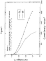
- the single cell results are shown in Figure 1 and demonstrate that good cell performances were obtained from the MEA comprising the lower cost, more manufacturable electrode of the invention.
- For operation on pure oxygen very high current densities of over 2.0 A/cm 2 were obtained.
- the oxidant will be air, and these applications will require that at least a current density of 500 mA/cm 2 is achieved.
- current densities up to 1.0 A/cm 2 were obtained, and the results represent performances typical of a satisfactorily performing MEA.
- a first particulate catalyst material was prepared by dispersing 80 weight parts of Shawinigan carbon black in 1200 parts of water. To this was added 20 weight parts of polytetrafluoroethylene solids (PTFE) as a dispersion in water (ICI Fluon GP1, 64 wt% solids suspension) and the mixture stirred to entrain the PTFE particles within the carbon catalyst materiaL The slurry was redispersed using a high shear mixer to produce a smooth mixture.
- PTFE polytetrafluoroethylene solids
- Chopped carbon fibres (Type RK 10, from RK Carbon Fibres Ltd, UK) at a fibre length of 37 mm were treated with GP1 polytetrafluoroethylene dispersion in water to give a 7 wt % coating on the fibres. Further RK10 fibres of length 12mm and lmm were similarly treated.
- the particulate catalyst mixture comprising 1.25g of solid material (carbon and PTFE components), was dispersed, with mixing, in demineralised water (500 cm 3 ) with 0.0105g of the 37mm teflonated fibres, 0.089g of the 12mm teflonated fibres and 0.43g of the 1mm teflonated fibres, 0.0485g of glass microfibre (Evanite 608 from Evanite Fibre Corporation, Corvallis, Oregon, USA) and 0.036g of polyvinylalcohol powder (BDH Chemcials, Poole, Dorset, UK).
- An electrode of the invention was fabricated from the resulting mixture, in a single step process, based on the principles of paper-making technology, as a sheet of size 214 cm 2 in a standard SCA sheet former (AB Lorentzen & Wettre, Box 4, S-163 93 Sweden). The sheet was air dried at 100°C, and then fired in air at a temperature in excess of 350°C.
- a second layer of a second particulate catalyst material was formed by applying an ink, comprising 40 wt % platinum catalyst, supported on carbon black (Johnson Matthey FC-40) in a 9.5% dispersion of Nafion EW1100 (E I DuPont De Nemours & Co.) in water, prepared according to methods described in EPA 731,520, to an Optimat 203 carbon fibre mat of density 10 g/m 2 , and air dried at 100°C.
- the platinum loading was 0.78 mg/cm 2 geometric area of carbon fibre mat.
- the second catalyst containing electrode layer was applied to one face of the first electrode layer and the layers were pressed at 200lb per square inch to compact the layers.
- the combined two electrode layers formed the cathode of an MEA, with the platinum catalyst containing face of the cathode being bonded to the membrane electrolyte face.
- the membrane electrolyte was Nafion 115.
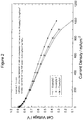
- the single cell results are shown in Figure 2.
- Example 2 The preparation of the cathode as described in Example 2 was followed, with the exception that the glass microfibre content (Evanite 608), in the first particulate catalyst mixture was increased to 0.097 g.
- the MEA was fabricated as described in Example 2. The single cell results are shown in Figure 2.
- the first particulate catalyst material was prepared as described for the first particulate material in Example 2.
- a second particulate catalyst material was prepared by dispersing 85 weight parts of carbon black (Vulcan XC72R, from Cabot Corp, Billerica, Mass, USA) in 1200 parts of water. To this was added 15 weight parts of polytetrafluoroethylene solids (from GP1 solution) and the mixture stirred to entrain the PTFE particles within the carbon catalyst material. The slurry was redispersed using a high shear mixer to produce a smooth mixture.
- An electrode of the invention was fabricated from the resulting mixture, in a single step process, based on the principles of paper-making technology, as a sheet of size 214 cm 2 in a standard SCA sheet former (AB Lorentzen & Wettre, Box 4, S-163 93 Sweden). The sheet was air dried at 100°C, and then fired in air at a temperature in excess of 350°C.
- a further cathode electrode layer comprising a platinum catalyst material was prepared as described in Example 2.
- the complete cathode and MEA were fabricated as described in Example 2.
- the single cell results for operation on air are shown in Figure 2.
- Examples 2, 3 and 4 in which the electrodes of the invention were produced by an even lower cost and more manufacturable single process step, by incorporating the catalyst components with the non-woven fibre materials, again produced MEAs with very acceptable current vs voltage performance characteristics.
- Comparison of Examples 2 and 3 illustrate that the high current density performance was markedly influenced by the composition of the fibre mix employed to fabricate the electrode, with the Example 3 demonstrating improved high current density performance due to improved mass transport properties. This feature of the electrode is particularly important for applications of the PEMFC in powering vehicles, where cell operation at ever increasing current densities is a requirement to reduce the size, weight and cost of the fuel cell stack.
Abstract
Description
- The present invention relates to a novel gas diffusion electrode structure which is of use in electrochemical devices, particularly fuel cells, and a process for the manufacture of the novel gas diffusion electrode structure.
- Electrochemical cells invariably comprise at their fundamental level a solid or liquid electrolyte and two electrodes, the anode and cathode, at which the desired electrochemical reactions take place. Gas diffusion electrodes are employed in a range of electrochemical devices, in which a gaseous reactant and/or product has to be diffused into and/or out of one of the cell electrode structures. They are designed to optimise the contact between the reactant and the electrolyte to maximise the reaction rate. Catalysts are often incorporated into gas diffusion electrode structures to increase the rates of the desired electrode reactions.
- Gas diffusion electrodes are employed in many different electrochemical devices, including metal-air batteries, electrochemical gas sensors, electrosynthesis of useful chemical compounds, and in particular, fuel cells.
- A fuel cell is an energy conversion device that efficiently converts the stored chemical energy of its fuel into electrical energy by combining either hydrogen, stored as a gas, or methanol stored as a liquid or gas, with oxygen to generate electrical power. The hydrogen or methanol are oxidised at the anode and oxygen is reduced at the cathode. Both electrodes are of the gas diffusion type. The electrolyte has to be in contact with both electrodes and may be acidic or alkaline, liquid or solid, in nature. In proton exchange membrane fuel cells (PEMFC), the electrolyte is a solid proton-conducting polymer membrane, commonly based on perfluorosulphonic acid materials, and the combined structure formed from the membrane and the two gas diffusion electrodes is known as the membrane electrode assembly (MEA). The anode gas diffusion electrode is designed to be porous and allow the reactant hydrogen or methanol to enter the electrode from the face of the electrode exposed to the reactant fuel supply, and diffuse through the thickness of the electrode to the reaction sites which contain catalysts, usually platinum metal based, to maximise the electrochemical oxidation of hydrogen or methanol. The anode is also designed to allow electrolyte to penetrate through the face of the electrode exposed to the electrolyte and to also contact the same reaction sites. With acidic electrolyte types the product of the anode reaction are protons and these can then be efficiently transported from the anode reaction sites through the electrolyte to the cathode gas diffusion electrode. The cathode is also designed to be porous and allow oxygen or air to enter the electrode and diffuse through to the reaction sites. Catalysts are again commonly incorporated to maximise the rate of the reaction at the cathode reaction sites which combines the protons with oxygen to produce water. Product water then has to diffuse out of the electrode structure. The structure of the cathode has to be designed such that it enables the efficient removal of the product water. If water builds up in the electrode, it becomes more difficult for the reactant oxygen to diffuse to the reaction sites, and thus the performance of the fuel cell decreases.
- Conventionally, the gas diffusion electrodes of the PEMFC, and indeed other devices, comprise many components and are typically made up of one, two or even more layers of these components. Typically the gas diffusion electrode will comprise one or more catalyst containing layers, which are supported onto a more rigid porous substrate layer. The catalyst containing layers enhance the desired electrode reactions and comprise a catalyst, which may be formed from a high surface area catalytic metal, often one of the precious metals, particularly platinum, either unsupported, as a metal black (for example US 4927514, EP 0357077), or in a very high surface area form in which it is dispersed and supported on a high surface area electrically conducting gas porous carbon black or graphite (for example US 4447505). The catalyst component may also be a non precious metal, such as one of the transition metals. In fuel cells which employ alkaline electrolytes, the cathode gas diffusion electrode can comprise catalysts based on macrocyclic compounds of cobalt (US 4179359,
EP 0 512 713). The catalyst layers may also comprise the high surface area carbon black itself, with no additional metal catalysts, in forexample EP 0 026 995 where the catalyst layer for an air depolarised cathode in a chlor-alkali cell comprises carbon black materials. - The catalyst layers also comprise other non-catalytic components in addition to the catalyst material usually polymeric materials which acts as binders to hold the electrode layer together and may also perform an additional function in controlling the hydrophobic/hydrophilic nature of the final structure. In the PEMFC in particular, the catalyst layers can also comprise other polymeric materials, such as proton conducting polymers, including forms of the proton conducting electrolyte itself, which are often mixed with the catalyst components or coated onto the catalyst containing layers, from solutions of the proton conducting polymer.
- These catalyst layers are usually formed into suitable mixtures of the components and deposited onto a suitable porous substrate, for example conducting carbon materials such as semi graphitised papers, cloths or foams, or particularly in the case of alkaline electrolyte systems, metal meshes such as nickel or stainless steel, or in the case of sensors, various forms of porous PTFE sheet. In the acid electrolyte PEMFC the substrate is usually based on carbon paper or woven cloth materials (
EP 0 026 995). These materials generally have a high bulk fibre density of greater than 0.4 g/cm3. The primary role of the substrate is to act as a physical support for the catalyst containing layers and to provide an electrically conducting structure in direct contact with the catalyst layer. Additionally it also enables a mechanically stable gas diffusion electrode to be produced. - A major problem with conventional gas diffusion electrodes based on the carbon fibre paper substrates is the lack of flexibility due to the rigid substrate that is typically used. The conventional electrodes are consequently easily damaged on handling which leads to high reject rates during the electrode and MEA fabrication process. This obviously has an impact on cost. With conventional gas diffusion electrodes based on woven cloth substrates a problem concerns the lack of good dimensional stability, as the cloth can easily be stretched in the directions of the major planar faces (x and y directions). This can make the manufacturing of electrodes and MEAs using these substrates very difficult and therefore costly.
- Furthermore the complexity of the conventional gas diffusion electrode requires a number of separate components such as the substrate and the catalyst layers to be brought together which results in a lengthy manufacturing process requiring a number of steps. Again, this increases the cost per unit of these gas diffusion electrodes to higher than is currently acceptable to make applications in power generation devices, such as fuel cells, commercially viable.
- It is therefore an object of the present invention to provide a gas diffusion electrode with both increased dimensional stability and flexibility and which can therefore be produced at lower cost. A further object of the present invention Is to provide an improved manufacturing process that is capable of producing large numbers of electrodes and MEAs at low unit cost, in high volumes and with high yields.
- Accordingly, the present invention provides a gas diffusion electrode comprising a non-woven network of fibres, one or more catalyst components and at least one polymeric substance characterised in that the catalyst component is embedded within the fibre network. Generally, the non-woven network of fibres has a density of less than 0.3 g/cm3, suitably less than 0.2 g/cm3 and preferably less than 0.1 g/cm3.
- The fibres, within the matrix, are normally randomly orientated in the x and y direction (in-plane) producing a two dimensional isotropic structure. Additionally, random orientation in the z direction (through-plane) occurs with the inclusion of very short fibres, typically lengths of ≤ 2mm or very fine fibres, typically of diameters ≤ 1 µm. It is also possible to introduce anisotropic character into the fibre matrix by using longer fibres, typically ≥50mm, in the composition, in combination with any method of laying down the layer that imparts a directional force into the mixture; such as extrusion or a paper making type processes. Fibres which are suitable for use in the present invention include carbon, glass, polymer, metal or ceramic fibres, preferably carbon, glass, metal or ceramic, typically of diameters in the range of 0.2µm to 50µm and with lengths from 0.05mm to 300mm, suitably 0.5mm to 150mm If fibres other than carbon fibres or other electrically conducting fibres are used it is necessary that the catalyst component comprises carbon and optionally one or more other catalyst components such as a metal or a metal supported on carbon in order that the final electrode structure is electrically conducting.
- By the term catalyst is meant a material that promotes or enhances the rate of the reaction of interest but remains unaltered by the reaction. The catalyst component or components selected will depend on the application for which the gas diffusion electrode is being used. These may be, for example, a precious metal or a transition metal as the metal or metal oxide, either unsupported or supported in a dispersed form on a carbon support; a carbon or an organic complex, in the form of a high surface area finely divided powder or fibre, or a combination of these options.
- The polymeric substances act as a binder to hold the electrode layer together. Depending on the polymeric substance used it may also act to provide essential electrode structural properties, such as control of the hydrophobic/hydrophilic balance. Examples of such polymers include polytetrafluoroethylene (PTFE), fluorinated ethylene-propylene (FEP), polyethylene, polypropylene, ethylene-propylene. The polymeric material can also act to provide the ionic conduction pathway in the electrode. Such proton conducting polymers are for example the perfluorosulphonic acid materials, produced by E.I. DuPont de Nemours, referred to as Nafion®.
- A first embodiment of the present invention provides a gas diffusion electrode as hereinbefore described wherein the catalyst component is one or more metals or their oxides in the form of finely divided unsupported powders or as metals in a dispersed form on a carbon support. Suitably the one or more metals may be a precious metal (Pt, Pd, Ru, Rh, Ir, Os, Au and Ag) or a transition metal selected from groups IVB, VB, VIB, VIIB, VIII, IB or IIB of the Periodic Table in "Handbook of Chemistry and Physics", 64th Edition, CRC Press, or a combination or alloy thereof. Preferably, the one or more metals is a precious metal, particularly Pt, or an alloy thereof,
- A second embodiment of the invention provides a gas diffusion electrode as hereinbefore described wherein the catalyst component is one or more carbon blacks.
- A major advantage of the present invention is that a free-standing, dimensionally stable and highly flexible gas diffusion electrode is obtained. The incidence of damage to the electrode on handling during manufacture is therefore minimised thus reducing the number of faulty or rejected electrodes, and consequently the cost is reduced. Furthermore, the intrinsic material cost is significantly reduced over carbon paper or woven cloths. In addition, the electrode of the invention is more amenable to high volume continuous production processes due to its high dimensional stability.
- A further advantage of the gas diffusion electrodes of the present invention is improved performance due to reduced mass transport losses. During operation of the PEM fuel cell, product water is produced at the cathode. This has to be efficiently removed from the electrode structure so that it does not build up in the structure and impede further oxygen diffusion (mass transport) to the reaction sites. With conventional electrodes this is not possible to fully achieve, and it becomes difficult to operate the cell efficiently at higher current densities, which is a desirable goal to improve power density. The presence of fibres in the catalyst layers can help to improve the efficiency of removal of the product water from the catalyst sites where it is produced into the reactant gas stream where it is transported out of the cell by the reactant gas flow. Accordingly, a further embodiment of the present invention provides a gas diffusion electrode suitable for use in electrochemical cells, said electrode comprising a current collector and a catalyst structure and characterised in that a continuous network of fibres for two-way transport is distributed in the catalyst containing layer.
- Gas diffusion electrodes of the present invention are suitable for low cost manufacture. The electrodes may be manufactured by one of two general methods.
- The electrodes may be manufactured by taking a pre-formed non-woven fibre material and applying the catalyst layers comprising the catalyst and polymeric materials. This can be done by any number of coating processes such as printing, rolling, K-bar or doctor blade methods.
- A second method for the manufacture of the gas diffusion electrode of the present invention and which provides a further aspect of the present invention, comprises mixing the fibres with at least one catalyst component or a polymeric substance and thereafter forming the gas diffusion electrode by adapting a continuous manufacturing process, for example paper-making, calendering or extrusion. For example, in a process based on paper-making technology, the fibres are dispersed in water with at least one catalyst component and a polymeric substance to form a dilute slurry and thereafter forming a continuous structure by the controlled deposition of said slurry onto a moving mesh bed, dewatering of the solids and drying/compaction of the fibre containing layer under a suitable time/pressure/temperature regime.
- A major advantage of this method is that the gas diffusion electrode is easily manufactured in a fewer number of steps using continuous manufacturing techniques such as conventional paper making techniques thus making it more cost effective and commercially viable. Using conventional paper making techniques, the fibres are dispersed as a dilute slurry in water with the catalyst component and the polymeric substance which can then be deposited and formed into a non-woven mat with the catalyst component embedded within the mat. The mat may be produced in continuous lengths with the prospect of producing the gas diffusion electrode in very large volumes with the minimum processing and in a very cost effective manner.
- A further advantage is that it is possible to combine two or more layers (at least one of the layers being an electrode of the invention) to form a multi-layer gas diffusion electrode structure at the same rate as a single layer could be produced.
- An additional advantage to be gained from this type of matrix structure, and the methods of fabrication, is that the incorporation of polymeric materials into the structure can be carefully controlled, unlike coatings applied to conventional materials such as carbon fibre paper and cloth where the applied polymer will coat all available surfaces. Both the fibres and the catalyst component or components may be precoated with the appropriate polymer or polymers, at the required loading, allowing the structure to contain any number of types of polymer, each located within specific areas of the structure. This gives the ability to tailor the hydrophobic/hydrophilic nature of the matrix to give improved performance characteristics. The incorporation of proton exchange polymers into the structure is also easily facilitated, as is the incorporation of thermoplastic polymer materials for hot forming the electrodes into specific shapes.
- The present invention also relates to a membrane electrode assembly and a method for the manufacture thereof wherein one or both of the electrodes are the gas diffusion electrode of the present invention. A still further aspect of the present invention relates to a fuel cell and a method for the manufacture thereof comprising at least one gas diffusion electrode of the present invention.
- The present invention is not limited to the use of the gas diffusion electrode in a fuel cell and any electrochemical device which comprises a gas diffusion electrode of the invention is within the scope.
- The structure of the present invention is not necessarily limited to gas diffusion electrodes but may also be useful in structures where a robust catalyst containing gas porous structure is required for such purposes as gas recombination in sealed batteries (to prevent pressure build up from the electrolysis of the electrolyte) and oxygen scavenging of enclosed systems that require the removal of oxygen to very low levels using the reaction with hydrogen.
- The present invention will now be described by way of example only which is not intended to be limiting thereof.
- The materials of the invention can be employed as either the anode or cathode, and indeed both anode and cathode in the electrochemical cells of the specific application. In the following examples, the electrodes are incorporated as the cathode in membrane electrode assemblies (MEAs) and evaluated in a proton exchange membrane fuel cell, with hydrogen as the anode fuel and air or pure oxygen as the cathode oxidant. It is at the cathode that the majority of cell performance (voltage) losses occur in cells operating with hydrogen as the fuel. The MEAs were fabricated by hot pressing the anode and cathode against each face of the solid proton conducting electrolyte membrane, as is commonly practised in the art.
- The anodes were of the more conventional type, currently widely employed in the PEMFC. They comprised a conventional pre-teflonated rigid conducting carbon fibre paper substrate (Toray TGP-H-090, available from Toray Industries Inc, Tokyo, Japan) to which was applied a layer of a 20 wt% platinum, 10 wt% ruthenium catalyst, supported on Cabot Vulcan XC72R (from Johnson Matthey Inc, New Jersey, USA), at an electrode platinum loading of 0.25 mg/cm2 of electrode geometric area. The MEAs were evaluated in a PEMFC single cell, with a geometric electrochemically active area of 50 cm2. The single cell consisted of graphite plates into which flowfields were machined to distribute reactant gases and humidification water, and remove products. The MEA was located between the flowfield plates. The operation of the single cell was controlled from a purpose built test station facility (from GlobeTech, of Bryans, Texas, USA). The "performance" of the fuel cell was assessed by measuring the voltage and current density relationship using a standard operating procedure. Unless otherwise stated, these conditions were typically, a reactant gas inlet temperature of 80°C, a pressure of both anode and cathode reactant gases of 3 atmospheres, and a reactant stoichiometry of 1.5 for hydrogen and 2.0 for air.
- A first particulate catalyst component was provided by dispersing 50 weight parts of a carbon black (Shawinigan black, from Chevron Chemicals, Houston, Texas, USA) in 1200 parts of demineralised water. To this was added 6 weight parts of polytetrafluoroethylene (PTFE) as a dispersion in water (ICI Fluon GP1, 64 wt% solids suspension) and the mixture stirred to entrain the PTFE particles within the carbon catalyst material. The slurry was redispersed using a high shear mixer to produce a smooth mixture.
- A second particulate catalyst material was provided by dispersing 100 weight parts of a 40 wt % platinum catalyst, supported on carbon black (Johnson Matthey FC-40) in 30 parts of a 9.5% dispersion of Nafion EW1100 (E I DuPont De Nemours & Co.) in water, prepared according to methods described in EPA 731,520. The particulate catalyst was dispersed using a high shear mixer to produce a smooth mixture.
- A pre-formed non-woven carbon fibre structure was a 17g/m2 (≡0.07g/cm3) density carbon fibre mat, supplied as Optimat 203 (from Technical Fibre Products, Kendal, Cumbria, UK). This was precoated with PTFE by soaking for 5 minutes in a solution of 120 parts by weight of GP1 PTFE emulsion in 2100 parts by weight of water then draining and allowing to dry. The coated carbon fibre mat was heated to 350°C in air to sinter the PTFE.
- The electrode of the invention was formed by pressing the first particulate catalyst material into the non-woven carbon fibre structure using a vacuum bed to remove the water and pull the particulate catalyst material into the structure. A total fill of 11.7g Shawinigan carbon per cm2 carbon fibre paper geometric area was achieved. The resulting sheet was pressed at 260°C and 1501b per sq inch for 2 minutes to compact the structure. A layer of the second particulate catalyst material was then applied to one face of the filled non-woven structure to provide a platinum loading of 0.76 mg/cm2 geometric area within the remaining carbon fibre structure and pressed at 2001b per square inch to compact the layer.
- The electrode formed the cathode of an MEA, with the face of the electrode comprising the platinum catalyst component bonded to the membrane electrolyte face. The membrane employed was Du Pont Nafion 112. The single cell results are shown in Figure 1 and demonstrate that good cell performances were obtained from the MEA comprising the lower cost, more manufacturable electrode of the invention. For operation on pure oxygen very high current densities of over 2.0 A/cm2 were obtained. For most practical applications of the PEMFC, the oxidant will be air, and these applications will require that at least a current density of 500 mA/cm2 is achieved. As illustrated in the Figure, current densities up to 1.0 A/cm2 were obtained, and the results represent performances typical of a satisfactorily performing MEA. It is worth noting that on air operation there was a tendency for the cell voltage to decrease more rapidly as the current density increased toward 1.0 A/cm2, compared to the pure oxygen data. This is an example of cell voltage decrease due to mass transport losses, relating to the ease with which reactant oxygen in air can diffuse to the electrode reaction sites. This is also a typical characteristic of cell current vs voltage plots seen with conventional MEAs, fabricated with electrodes comprising conducting substrates such as high density carbon fibre paper.
- A first particulate catalyst material was prepared by dispersing 80 weight parts of Shawinigan carbon black in 1200 parts of water. To this was added 20 weight parts of polytetrafluoroethylene solids (PTFE) as a dispersion in water (ICI Fluon GP1, 64 wt% solids suspension) and the mixture stirred to entrain the PTFE particles within the carbon catalyst materiaL The slurry was redispersed using a high shear mixer to produce a smooth mixture.
- Chopped carbon fibres (Type RK 10, from RK Carbon Fibres Ltd, UK) at a fibre length of 37 mm were treated with GP1 polytetrafluoroethylene dispersion in water to give a 7 wt % coating on the fibres. Further RK10 fibres of length 12mm and lmm were similarly treated.
- The particulate catalyst mixture, comprising 1.25g of solid material (carbon and PTFE components), was dispersed, with mixing, in demineralised water (500 cm3) with 0.0105g of the 37mm teflonated fibres, 0.089g of the 12mm teflonated fibres and 0.43g of the 1mm teflonated fibres, 0.0485g of glass microfibre (Evanite 608 from Evanite Fibre Corporation, Corvallis, Oregon, USA) and 0.036g of polyvinylalcohol powder (BDH Chemcials, Poole, Dorset, UK). An electrode of the invention was fabricated from the resulting mixture, in a single step process, based on the principles of paper-making technology, as a sheet of size 214 cm2 in a standard SCA sheet former (AB Lorentzen & Wettre, Box 4, S-163 93 Stockholm, Sweden). The sheet was air dried at 100°C, and then fired in air at a temperature in excess of 350°C.
- A second layer of a second particulate catalyst material, was formed by applying an ink, comprising 40 wt % platinum catalyst, supported on carbon black (Johnson Matthey FC-40) in a 9.5% dispersion of Nafion EW1100 (E I DuPont De Nemours & Co.) in water, prepared according to methods described in EPA 731,520, to an Optimat 203 carbon fibre mat of density 10 g/m2, and air dried at 100°C. The platinum loading was 0.78 mg/cm2 geometric area of carbon fibre mat.
- The second catalyst containing electrode layer was applied to one face of the first electrode layer and the layers were pressed at 200lb per square inch to compact the layers. The combined two electrode layers formed the cathode of an MEA, with the platinum catalyst containing face of the cathode being bonded to the membrane electrolyte face. The membrane electrolyte was Nafion 115. The single cell results are shown in Figure 2.
- The preparation of the cathode as described in Example 2 was followed, with the exception that the glass microfibre content (Evanite 608), in the first particulate catalyst mixture was increased to 0.097 g. The MEA was fabricated as described in Example 2. The single cell results are shown in Figure 2.
- The first particulate catalyst material was prepared as described for the first particulate material in Example 2. A second particulate catalyst material was prepared by dispersing 85 weight parts of carbon black (Vulcan XC72R, from Cabot Corp, Billerica, Mass, USA) in 1200 parts of water. To this was added 15 weight parts of polytetrafluoroethylene solids (from GP1 solution) and the mixture stirred to entrain the PTFE particles within the carbon catalyst material. The slurry was redispersed using a high shear mixer to produce a smooth mixture.
- A mixture of 7.8g of the first particulate catalyst mixture (equivalent to 0.603g of solids) was dispersed with a mixture of 7.8g of the second particulate catalyst mixture (equivalent to 0.603g of solids) in water (500 cm3) with 0.0105g of the 37mm teflonated fibres 0.089g of the 12mm teflonated fibres and 0.43g of the 1mm teflonated fibres, 0.097g of glass microfibre (Evanite 608) and 0.036g of polyvinylalcohol powder (BDH) using a blender mixer. An electrode of the invention was fabricated from the resulting mixture, in a single step process, based on the principles of paper-making technology, as a sheet of size 214 cm2 in a standard SCA sheet former (AB Lorentzen & Wettre, Box 4, S-163 93 Stockholm, Sweden). The sheet was air dried at 100°C, and then fired in air at a temperature in excess of 350°C.
- A further cathode electrode layer comprising a platinum catalyst material was prepared as described in Example 2. The complete cathode and MEA were fabricated as described in Example 2. The single cell results for operation on air are shown in Figure 2. Examples 2, 3 and 4, in which the electrodes of the invention were produced by an even lower cost and more manufacturable single process step, by incorporating the catalyst components with the non-woven fibre materials, again produced MEAs with very acceptable current vs voltage performance characteristics. Comparison of Examples 2 and 3 illustrate that the high current density performance was markedly influenced by the composition of the fibre mix employed to fabricate the electrode, with the Example 3 demonstrating improved high current density performance due to improved mass transport properties. This feature of the electrode is particularly important for applications of the PEMFC in powering vehicles, where cell operation at ever increasing current densities is a requirement to reduce the size, weight and cost of the fuel cell stack.
Claims (12)
- A gas diffusion electrode comprising a non-woven network of fibres, one or more catalysts components and at least one polymeric substance characterised in that the catalyst is embedded within the fibre network.
- A gas diffusion electrode according to claim 1 wherein the non-woven network of fibres has a density of less than 0.3g/cm2.
- A gas diffusion electrode according to claims 1 or 2 wherein the fibres are of carbon, glass, polymer, metal or ceramic.
- A gas diffusion electrode according to any preceding claim wherein the fibres are of diameter 0.2µm to 50µm.
- A gas diffusion electrode according to any preceding claim wherein the fibres are from 0.05mm to 300mm in length.
- A gas diffusion electrode according to any preceding claim wherein the catalyst component is one or more metals or their metal oxide, in the form of finely divided unsupported powders or as metals in a dispersed form on a carbon support.
- A gas diffusion electrode according to claim 6 wherein the catalyst component is selected from one or more precious metals or a transition metal or a combination or alloy thereof
- A gas diffusion electrode according to any one of claims 1 to 5 wherein the catalyst component is one or more carbon blacks.
- A method for the manufacture of the gas diffusion electrode according to any preceding claim comprising mixing the fibres with at least one catalyst component or a polymeric substance and thereafter forming the gas diffusion electrode by adapting a continuous manufacturing process.
- A method according to claim 9 wherein the continuous manufacturing process is based on paper-making technology.
- A membrane electrode assembly wherein one or both of the gas diffusion electrodes is an electrode according to any one of claims 1 to 8.
- A fuel cell which comprises a gas diffusion electrode according to any one of claims 1 to 8.
Priority Applications (1)
| Application Number | Priority Date | Filing Date | Title |
|---|---|---|---|
| EP99109991A EP0942482B1 (en) | 1996-02-28 | 1997-02-13 | Use of catalytically active gas diffusion electrodes comprising a nonwoven fibrous structure in a Direct Methanol Fuel Cell |
Applications Claiming Priority (4)
| Application Number | Priority Date | Filing Date | Title |
|---|---|---|---|
| GBGB9604191.8A GB9604191D0 (en) | 1996-02-28 | 1996-02-28 | Water transport in electrodes |
| GB9604191 | 1996-02-28 | ||
| GBGB9626802.4A GB9626802D0 (en) | 1996-12-23 | 1996-12-23 | Gas diffusion electrodes |
| GB9626802 | 1996-12-23 |
Related Child Applications (1)
| Application Number | Title | Priority Date | Filing Date |
|---|---|---|---|
| EP99109991A Division EP0942482B1 (en) | 1996-02-28 | 1997-02-13 | Use of catalytically active gas diffusion electrodes comprising a nonwoven fibrous structure in a Direct Methanol Fuel Cell |
Publications (3)
| Publication Number | Publication Date |
|---|---|
| EP0791974A1 true EP0791974A1 (en) | 1997-08-27 |
| EP0791974B1 EP0791974B1 (en) | 2000-01-12 |
| EP0791974B2 EP0791974B2 (en) | 2005-08-17 |
Family
ID=26308820
Family Applications (2)
| Application Number | Title | Priority Date | Filing Date |
|---|---|---|---|
| EP97300921A Expired - Lifetime EP0791974B2 (en) | 1996-02-28 | 1997-02-13 | Catalytically active gas diffusion electrodes comprising a nonwoven fibrous structure |
| EP99109991A Expired - Lifetime EP0942482B1 (en) | 1996-02-28 | 1997-02-13 | Use of catalytically active gas diffusion electrodes comprising a nonwoven fibrous structure in a Direct Methanol Fuel Cell |
Family Applications After (1)
| Application Number | Title | Priority Date | Filing Date |
|---|---|---|---|
| EP99109991A Expired - Lifetime EP0942482B1 (en) | 1996-02-28 | 1997-02-13 | Use of catalytically active gas diffusion electrodes comprising a nonwoven fibrous structure in a Direct Methanol Fuel Cell |
Country Status (8)
| Country | Link |
|---|---|
| US (2) | US5865968A (en) |
| EP (2) | EP0791974B2 (en) |
| JP (1) | JP3576739B2 (en) |
| AU (1) | AU717536B2 (en) |
| BR (1) | BR9701086A (en) |
| CA (1) | CA2198553C (en) |
| DE (2) | DE69709784T2 (en) |
| ES (1) | ES2141578T3 (en) |
Cited By (35)
| Publication number | Priority date | Publication date | Assignee | Title |
|---|---|---|---|---|
| EP0875524A2 (en) * | 1997-04-25 | 1998-11-04 | Johnson Matthey Public Limited Company | Composite membranes |
| EP0928036A1 (en) * | 1998-01-02 | 1999-07-07 | De Nora S.P.A. | Carbon-cloth-based electrocatalytic gas diffusion electrodes of electrochemical cells and method of manufacture |
| WO2000024074A1 (en) * | 1998-10-16 | 2000-04-27 | Johnson Matthey Public Limited Company | Process for preparing a solid polymer electrolyte membrane |
| WO2000047816A1 (en) * | 1999-02-15 | 2000-08-17 | Johnson Matthey Public Limited Company | Nonwoven web |
| EP1050915A1 (en) * | 1998-01-20 | 2000-11-08 | Daikin Industries, Ltd. | Material for electrode |
| EP1063716A2 (en) * | 1999-06-22 | 2000-12-27 | Johnson Matthey Public Limited Company | Carbon fibers containing non-woven fibre web for use as gas diffusion electrode substrate in fuel cells |
| WO2001004980A1 (en) * | 1999-07-07 | 2001-01-18 | Sgl Carbon Ag | Electrode substrate for electrochemical cells based on low-cost manufacturing processes |
| GB2352868A (en) * | 1999-07-30 | 2001-02-07 | Aisin Seiki | A solid polymer electrolyte cell |
| WO2001037359A2 (en) * | 1999-11-18 | 2001-05-25 | Proton Energy Systems, Inc. | High differential pressure electrochemical cell |
| EP1139476A2 (en) * | 2000-03-31 | 2001-10-04 | Kabushiki Kaisha Equos Research | Fuel cell and fuel cell device |
| WO2002005375A1 (en) * | 2000-07-08 | 2002-01-17 | Johnson Matthey Public Limited Company | Improved material for electrode manufacture |
| WO2002031841A2 (en) * | 2000-10-11 | 2002-04-18 | Carl Freudenberg Kg | Conductive nonwoven |
| WO2002035624A2 (en) * | 2000-10-21 | 2002-05-02 | Ballard Power Systems Inc. | Membrane electrode arrangement with an optimised electrode structure |
| WO2002039526A1 (en) * | 2000-11-07 | 2002-05-16 | Johnson Matthey Public Limited Company | Gas diffusion substrate |
| US6479188B1 (en) | 1999-10-13 | 2002-11-12 | The Gillette Company | Cathode tube and method of making the same |
| EP1263073A1 (en) * | 2001-05-31 | 2002-12-04 | Asahi Glass Co., Ltd. | Membrane-electrode assembly for solid polymer electrolyte fuel cells and process for its production |
| US6531240B1 (en) | 1999-03-16 | 2003-03-11 | Johnson Matthey Public Limited Company | Gas diffusion substrates |
| EP1354366A1 (en) * | 2001-01-16 | 2003-10-22 | Showa Denko K.K. | Catalyst composition for cell, gas diffusion layer, and fuel cell comprising the same |
| EP1519433A1 (en) * | 2003-09-26 | 2005-03-30 | Samsung SDI Co., Ltd. | Diffusion electrode for fuel cell |
| US6949308B2 (en) | 2000-04-17 | 2005-09-27 | Johnson Matthey Public Limited Company | Gas diffusion substrate |
| WO2005124902A1 (en) * | 2004-06-15 | 2005-12-29 | Johnson Matthey Public Limited Company | Gas diffusion substrate |
| WO2006021740A1 (en) | 2004-08-27 | 2006-03-02 | Johnson Matthey Public Limited Company | Platinum alloy catalyst |
| US7014944B2 (en) * | 2000-07-25 | 2006-03-21 | Apollo Energy Systems, Incorporated | Electrodes for alkaline fuel cells with circulating electrolyte |
| WO2006046033A1 (en) * | 2004-10-27 | 2006-05-04 | Johnson Matthey Public Limited Company | Fuel cell stack |
| US7052792B2 (en) | 2000-03-17 | 2006-05-30 | Johnson Matthey Public Limited Company | Proton conducting polymer membrane for electrochemical cell |
| US7144476B2 (en) | 2002-04-12 | 2006-12-05 | Sgl Carbon Ag | Carbon fiber electrode substrate for electrochemical cells |
| US7338732B1 (en) | 1999-06-17 | 2008-03-04 | Johnson Matthey Public Limited Company | Gas diffusion substrate and electrode |
| US7396611B2 (en) | 2003-12-15 | 2008-07-08 | Plug Power Inc. | Fuel cell catalyst layer |
| US7405021B2 (en) | 2000-07-08 | 2008-07-29 | Johnson Matthey Public Limited Company | Water-retaining anode structure for a fuel cell |
| US7916631B2 (en) | 2000-11-28 | 2011-03-29 | Microsoft Corporation | Load balancing in set top cable box environment |
| WO2013057483A1 (en) | 2011-10-19 | 2013-04-25 | Johnson Matthey Fuel Cells Limited | Gas diffusion substrate |
| US8685574B2 (en) | 2006-02-01 | 2014-04-01 | Johnson Matthey Public Limited Company | Microporous Layer |
| WO2014205259A1 (en) | 2013-06-20 | 2014-12-24 | Gencell Ltd. | Gas diffusion electrode and process for making same |
| CN104981929A (en) * | 2013-02-13 | 2015-10-14 | 东丽株式会社 | Fuel-cell gas dispersion layer, and method for producing same |
| WO2020065455A1 (en) * | 2018-09-24 | 2020-04-02 | 3M Innovative Properties Company | Porous electrode, membrane-electrode assembly, liquid flow battery and method of making a porous electrode |
Families Citing this family (55)
| Publication number | Priority date | Publication date | Assignee | Title |
|---|---|---|---|---|
| JP3583897B2 (en) * | 1997-04-11 | 2004-11-04 | 三洋電機株式会社 | Fuel cell |
| GB2337150B (en) * | 1998-05-07 | 2000-09-27 | Nat Power Plc | Carbon based electrodes |
| JP3888057B2 (en) * | 1998-05-27 | 2007-02-28 | 東レ株式会社 | Carbon fiber paper for polymer electrolyte fuel cells |
| DE19837669A1 (en) * | 1998-08-20 | 2000-03-09 | Degussa | Catalyst layer for polymer electrolyte fuel cells |
| WO2000045448A2 (en) * | 1999-01-22 | 2000-08-03 | California Institute Of Technology | Improved membrane electrode assembly for a fuel cell |
| GB9914499D0 (en) * | 1999-06-22 | 1999-08-25 | Johnson Matthey Plc | Non-woven fibre webs |
| CN1205685C (en) | 1999-11-17 | 2005-06-08 | 尼电源系统公司 | Fuel cells having silicon substrates and/or sol-gel derived support structures |
| CN1307376A (en) | 2000-01-27 | 2001-08-08 | 钟馨稼 | Rechargeable solid Cr-F-Li accumulator |
| EP1942536B1 (en) * | 2000-01-27 | 2012-03-14 | Mitsubishi Rayon Co., Ltd. | Porous carbon electrode substrate |
| DE10027339A1 (en) * | 2000-06-02 | 2001-12-06 | Bayer Ag | Dimensionally stable gas diffusion electrode |
| US6740220B1 (en) * | 2000-07-28 | 2004-05-25 | The United States Of America As Represented By The Secretary Of The Navy | Electrocatalytic cathode device of palladium and iridium on a high density or porous carbon support and a method for making such a cathode |
| US6733639B2 (en) * | 2000-11-13 | 2004-05-11 | Akzo Nobel N.V. | Electrode |
| US20030091891A1 (en) * | 2001-01-16 | 2003-05-15 | Tomoaki Yoshida | Catalyst composition for cell, gas diffusion layer, and fuel cell comprising the same |
| US6797422B2 (en) | 2001-01-25 | 2004-09-28 | Gas Technology Institute | Air-breathing direct methanol fuel cell with metal foam current collectors |
| JP2005505095A (en) * | 2001-02-23 | 2005-02-17 | エヴィオニクス,インコーポレイティッド | Fibrous electrodes for metal-air electrochemical cells |
| ITMI20010402A1 (en) * | 2001-02-28 | 2002-08-28 | De Nora Elettrodi Spa | NEW ELECTROCATALYTIC COMPOSITION FOR DEPOLARIZED OXYGEN CATHODE |
| US6500319B2 (en) * | 2001-04-05 | 2002-12-31 | Giner Electrochemical Systems, Llc | Proton exchange membrane (PEM) electrochemical cell having an integral, electrically-conductive, compression pad |
| GB0112021D0 (en) | 2001-05-17 | 2001-07-11 | Johnson Matthey Plc | Substrate |
| US7601262B1 (en) | 2001-06-22 | 2009-10-13 | Argonide Corporation | Sub-micron filter |
| US7147761B2 (en) * | 2001-08-13 | 2006-12-12 | Mine Safety Appliances Company | Electrochemical sensor |
| US7094492B2 (en) * | 2001-10-11 | 2006-08-22 | Honda Giken Kogyo Kabushiki Kaisha | Electrode for polymer electrolyte fuel cell |
| US6716549B2 (en) * | 2001-12-27 | 2004-04-06 | Avista Laboratories, Inc. | Fuel cell having metalized gas diffusion layer |
| US20040001991A1 (en) * | 2002-07-01 | 2004-01-01 | Kinkelaar Mark R. | Capillarity structures for water and/or fuel management in fuel cells |
| DE10244228B4 (en) * | 2002-09-23 | 2008-01-17 | Proton Motor Fuel Cell Gmbh | Process for producing a gas diffusion electrode and its use |
| JP4130792B2 (en) * | 2002-11-25 | 2008-08-06 | 本田技研工業株式会社 | Membrane-electrode structure and polymer electrolyte fuel cell using the same |
| NO320029B1 (en) * | 2003-07-07 | 2005-10-10 | Revolt Technology As | Method of producing gas diffusion electrodes |
| US7455928B2 (en) * | 2003-08-18 | 2008-11-25 | General Motors Corporation | Diffusion media for use in a PEM fuel cell |
| WO2005024981A2 (en) * | 2003-09-03 | 2005-03-17 | Hollingsworth & Vose Company | Fuel cell gas diffusion layer |
| WO2005027244A2 (en) * | 2003-09-10 | 2005-03-24 | Hollingsworth & Vose Company | Fuel cell gas diffusion layer |
| DE10342199B4 (en) * | 2003-09-13 | 2007-02-08 | Daimlerchrysler Ag | Method for producing a gas diffusion layer for a fuel cell |
| US7629071B2 (en) * | 2004-09-29 | 2009-12-08 | Giner Electrochemical Systems, Llc | Gas diffusion electrode and method of making the same |
| US7632589B2 (en) * | 2005-01-14 | 2009-12-15 | Panasonic Corporation | Fuel-cell stack and fuel cell |
| GB2422716B (en) * | 2005-01-26 | 2007-08-22 | Intelligent Energy Ltd | Multi-layer fuel cell diffuser |
| JP2006219694A (en) * | 2005-02-08 | 2006-08-24 | Permelec Electrode Ltd | Gas diffusion electrode |
| US7390343B2 (en) * | 2005-09-12 | 2008-06-24 | Argonide Corporation | Drinking water filtration device |
| EP1931441A1 (en) * | 2005-09-12 | 2008-06-18 | Argonide Corporation | Electrostatic air filter |
| US20080280190A1 (en) * | 2005-10-20 | 2008-11-13 | Robert Brian Dopp | Electrochemical catalysts |
| EP1780822B1 (en) * | 2005-11-01 | 2012-01-18 | Tomoegawa Co., Ltd. | Gas diffusion electrode, membrane-electrode assembly, polymer electrolyte fuel cell, and methods for producing |
| US7955755B2 (en) * | 2006-03-31 | 2011-06-07 | Quantumsphere, Inc. | Compositions of nanometal particles containing a metal or alloy and platinum particles |
| JP4898568B2 (en) * | 2007-06-15 | 2012-03-14 | 株式会社ノリタケカンパニーリミテド | Catalyst layer and membrane-electrode assembly |
| KR100957302B1 (en) * | 2007-09-07 | 2010-05-12 | 현대자동차주식회사 | Method for manufacturing Membrane-Electrode Assembly |
| WO2011114949A1 (en) * | 2010-03-19 | 2011-09-22 | 旭硝子株式会社 | Membrane electrode assembly for solid polymer fuel cell, and method for producing cathode for solid polymer fuel cell |
| WO2012040738A1 (en) * | 2010-09-24 | 2012-03-29 | The Government Of The United States Of America, As Represented By The Secretary Of The Navy | Dual-function air cathode nanoarchitectures for metal-air batteries with pulse-power capability |
| DE102010042729A1 (en) * | 2010-10-21 | 2012-04-26 | Bayer Materialscience Aktiengesellschaft | Oxygenated cathode and process for its preparation |
| US9123963B2 (en) * | 2011-03-25 | 2015-09-01 | GM Global Technology Operations LLC | Direct coated membrane electrode assembly on external reinforcement for fuel cells |
| US8962213B2 (en) * | 2011-03-25 | 2015-02-24 | GM Global Technology Operations LLC | Direct catalyst coating on free standing microporous layer |
| WO2013021145A1 (en) | 2011-08-11 | 2013-02-14 | Cmr Fuel Cells (Uk) Limited | Improvements in or relating to catalysts |
| GB201121898D0 (en) | 2011-12-20 | 2012-02-01 | Ucl Business Plc | Fuel cell |
| US9108968B2 (en) | 2012-04-25 | 2015-08-18 | Ppg Industries Ohio, Inc. | Methods for producing 1,5,7-triazabicyclo[4.4.0]dec-5-ene by reaction of a disubstituted carbodiimide and dipropylene triamine |
| CN104507548A (en) | 2012-06-27 | 2015-04-08 | 阿尔戈耐德公司 | Aluminized silicious sorbent and water purification device incorporating the same |
| GB201401952D0 (en) | 2014-02-05 | 2014-03-19 | Johnson Matthey Fuel Cells Ltd | Gas diffusion substrate |
| DE102014226714A1 (en) | 2014-12-19 | 2015-11-19 | Heraeus Deutschland GmbH & Co. KG | catalyst fleece |
| JP6182741B2 (en) * | 2015-12-15 | 2017-08-23 | パナソニックIpマネジメント株式会社 | Electrode for electrolyzer, electrolyzer, and method for producing electrolyzed product |
| CN110506352B (en) * | 2017-04-13 | 2022-06-17 | 贝卡尔特公司 | Gas diffusion layer |
| US20230127900A1 (en) * | 2021-10-22 | 2023-04-27 | Bell Textron Inc. | Fuel Cell Metallic Gas Diffusion Layer |
Citations (8)
| Publication number | Priority date | Publication date | Assignee | Title |
|---|---|---|---|---|
| JPS62156285A (en) * | 1985-12-27 | 1987-07-11 | Tanaka Kikinzoku Kogyo Kk | Gas diffusing electrode and its production |
| JPS62184768A (en) * | 1986-02-06 | 1987-08-13 | Tanaka Kikinzoku Kogyo Kk | Manufacture of gas diffusion electrode |
| JPS62232861A (en) * | 1986-04-01 | 1987-10-13 | Tanaka Kikinzoku Kogyo Kk | Gas diffusion electrode and manufacture thereof |
| JPS62232860A (en) * | 1986-04-01 | 1987-10-13 | Tanaka Kikinzoku Kogyo Kk | Gas diffusion electrode and manufacture thereof |
| EP0582333A1 (en) * | 1992-08-03 | 1994-02-09 | Metallgesellschaft Ag | Antipercolation gas-diffusion electrode and method of making same |
| US5308465A (en) * | 1991-12-12 | 1994-05-03 | Metallgesellschaft Aktiengesellschaft | Membrane for a gas diffusion electrode, process of manufacturing the membrane, and gas diffusion electrode provided with the membrane |
| JPH06267555A (en) * | 1993-03-10 | 1994-09-22 | Mitsubishi Electric Corp | Electrochemical device |
| EP0654837A1 (en) * | 1993-11-23 | 1995-05-24 | Johnson Matthey Public Limited Company | Manufacture of electrodes |
Family Cites Families (21)
| Publication number | Priority date | Publication date | Assignee | Title |
|---|---|---|---|---|
| US3203834A (en) * | 1961-07-26 | 1965-08-31 | Leesona Corp | Fuel cell |
| FR1499879A (en) * | 1965-12-16 | 1967-11-03 | Inst Francais Du Petrole | New fuel cell electrodes and their manufacturing process |
| US3544381A (en) * | 1967-10-05 | 1970-12-01 | Hooker Chemical Corp | Fuel cell with wicking-type electrode |
| US3706602A (en) * | 1969-12-18 | 1972-12-19 | Hooker Chemical Corp | Fuel cell electrode structure utilizing capillary action |
| JPS50334A (en) * | 1973-05-08 | 1975-01-06 | ||
| JPS5318603B2 (en) † | 1973-07-10 | 1978-06-16 | ||
| US3972735A (en) * | 1974-02-15 | 1976-08-03 | United Technologies Corporation | Method for making electrodes for electrochemical cells |
| US4115627A (en) * | 1977-08-15 | 1978-09-19 | United Technologies Corporation | Electrochemical cell comprising a ribbed electrode substrate |
| US4185131A (en) † | 1978-06-28 | 1980-01-22 | United Technologies Corporation | Screen printing method for making an electrochemical cell electrode |
| US4680100A (en) * | 1982-03-16 | 1987-07-14 | American Cyanamid Company | Electrochemical cells and electrodes therefor |
| EP0184638B1 (en) * | 1984-10-17 | 1990-02-28 | Hitachi, Ltd. | Process of producing a flexbile fuel cell electrode from a carbon paper |
| US4647359A (en) * | 1985-10-16 | 1987-03-03 | Prototech Company | Electrocatalytic gas diffusion electrode employing thin carbon cloth layer |
| DE3672589D1 (en) * | 1985-12-09 | 1990-08-16 | Dow Chemical Co | METHOD FOR PRODUCING A SOLID POLYMER ELECTROLYTE ELECTRODE WITH A LIQUID OR WITH A SOLVENT. |
| DE3672975D1 (en) * | 1985-12-09 | 1990-08-30 | Dow Chemical Co | SOLID POLYMER ELECTROLYTE ELECTRODE. |
| US4729932A (en) * | 1986-10-08 | 1988-03-08 | United Technologies Corporation | Fuel cell with integrated cooling water/static water removal means |
| US4780437A (en) * | 1987-02-11 | 1988-10-25 | The United States Of America As Represented By The United States Department Of Energy | Fabrication of catalytic electrodes for molten carbonate fuel cells |
| US5234776A (en) * | 1990-08-03 | 1993-08-10 | Fuji Electric Co., Ltd. | Solid polymer electrolyte fuel cell system with ribbed configuration |
| JP3107229B2 (en) * | 1991-02-14 | 2000-11-06 | 田中貴金属工業株式会社 | Diaphragm humidification structure of solid polymer electrolyte fuel cell and electrolytic cell |
| US5242765A (en) * | 1992-06-23 | 1993-09-07 | Luz Electric Fuel Israel Limited | Gas diffusion electrodes |
| US5292600A (en) * | 1992-08-13 | 1994-03-08 | H-Power Corp. | Hydrogen power cell |
| DE19544323A1 (en) † | 1995-11-28 | 1997-06-05 | Magnet Motor Gmbh | Gas diffusion electrode for polymer electrolyte membrane fuel cells |
-
1997
- 1997-02-13 EP EP97300921A patent/EP0791974B2/en not_active Expired - Lifetime
- 1997-02-13 DE DE69709784T patent/DE69709784T2/en not_active Expired - Fee Related
- 1997-02-13 DE DE69701103T patent/DE69701103T3/en not_active Expired - Lifetime
- 1997-02-13 ES ES97300921T patent/ES2141578T3/en not_active Expired - Lifetime
- 1997-02-13 EP EP99109991A patent/EP0942482B1/en not_active Expired - Lifetime
- 1997-02-18 AU AU14737/97A patent/AU717536B2/en not_active Ceased
- 1997-02-19 US US08/802,556 patent/US5865968A/en not_active Expired - Fee Related
- 1997-02-26 CA CA002198553A patent/CA2198553C/en not_active Expired - Fee Related
- 1997-02-26 BR BR9701086A patent/BR9701086A/en active Search and Examination
- 1997-02-28 JP JP04625897A patent/JP3576739B2/en not_active Expired - Fee Related
-
1998
- 1998-11-12 US US09/189,842 patent/US6010606A/en not_active Expired - Lifetime
Patent Citations (8)
| Publication number | Priority date | Publication date | Assignee | Title |
|---|---|---|---|---|
| JPS62156285A (en) * | 1985-12-27 | 1987-07-11 | Tanaka Kikinzoku Kogyo Kk | Gas diffusing electrode and its production |
| JPS62184768A (en) * | 1986-02-06 | 1987-08-13 | Tanaka Kikinzoku Kogyo Kk | Manufacture of gas diffusion electrode |
| JPS62232861A (en) * | 1986-04-01 | 1987-10-13 | Tanaka Kikinzoku Kogyo Kk | Gas diffusion electrode and manufacture thereof |
| JPS62232860A (en) * | 1986-04-01 | 1987-10-13 | Tanaka Kikinzoku Kogyo Kk | Gas diffusion electrode and manufacture thereof |
| US5308465A (en) * | 1991-12-12 | 1994-05-03 | Metallgesellschaft Aktiengesellschaft | Membrane for a gas diffusion electrode, process of manufacturing the membrane, and gas diffusion electrode provided with the membrane |
| EP0582333A1 (en) * | 1992-08-03 | 1994-02-09 | Metallgesellschaft Ag | Antipercolation gas-diffusion electrode and method of making same |
| JPH06267555A (en) * | 1993-03-10 | 1994-09-22 | Mitsubishi Electric Corp | Electrochemical device |
| EP0654837A1 (en) * | 1993-11-23 | 1995-05-24 | Johnson Matthey Public Limited Company | Manufacture of electrodes |
Non-Patent Citations (4)
| Title |
|---|
| PATENT ABSTRACTS OF JAPAN vol. 011, no. 398 (C - 466) 25 December 1987 (1987-12-25) * |
| PATENT ABSTRACTS OF JAPAN vol. 012, no. 026 (E - 577) 26 January 1988 (1988-01-26) * |
| PATENT ABSTRACTS OF JAPAN vol. 012, no. 101 (E - 595) 2 April 1988 (1988-04-02) * |
| PATENT ABSTRACTS OF JAPAN vol. 018, no. 672 (E - 1646) 19 December 1994 (1994-12-19) * |
Cited By (60)
| Publication number | Priority date | Publication date | Assignee | Title |
|---|---|---|---|---|
| EP0875524A3 (en) * | 1997-04-25 | 1999-04-07 | Johnson Matthey Public Limited Company | Composite membranes |
| US6042958A (en) * | 1997-04-25 | 2000-03-28 | Johnson Matthey Public Limited Company | Composite membranes |
| EP0875524A2 (en) * | 1997-04-25 | 1998-11-04 | Johnson Matthey Public Limited Company | Composite membranes |
| EP0928036A1 (en) * | 1998-01-02 | 1999-07-07 | De Nora S.P.A. | Carbon-cloth-based electrocatalytic gas diffusion electrodes of electrochemical cells and method of manufacture |
| EP1050915A4 (en) * | 1998-01-20 | 2001-05-23 | Daikin Ind Ltd | Material for electrode |
| EP1050915A1 (en) * | 1998-01-20 | 2000-11-08 | Daikin Industries, Ltd. | Material for electrode |
| US6416896B1 (en) | 1998-01-20 | 2002-07-09 | Daikin Industries, Ltd. | Material for electrode comprising a non-woven fabric composed of a fluorine-containing resin fiber |
| WO2000024074A1 (en) * | 1998-10-16 | 2000-04-27 | Johnson Matthey Public Limited Company | Process for preparing a solid polymer electrolyte membrane |
| WO2000047816A1 (en) * | 1999-02-15 | 2000-08-17 | Johnson Matthey Public Limited Company | Nonwoven web |
| US6531240B1 (en) | 1999-03-16 | 2003-03-11 | Johnson Matthey Public Limited Company | Gas diffusion substrates |
| US7678162B2 (en) | 1999-06-17 | 2010-03-16 | Johnson Matthey Public Limited Company | Gas diffusion substrate and electrode |
| US7338732B1 (en) | 1999-06-17 | 2008-03-04 | Johnson Matthey Public Limited Company | Gas diffusion substrate and electrode |
| US6677073B1 (en) | 1999-06-22 | 2004-01-13 | Johnson Matthey Public Limited Company | Non-woven fiber webs |
| EP1063716A2 (en) * | 1999-06-22 | 2000-12-27 | Johnson Matthey Public Limited Company | Carbon fibers containing non-woven fibre web for use as gas diffusion electrode substrate in fuel cells |
| EP1063716B1 (en) * | 1999-06-22 | 2014-10-08 | Johnson Matthey Fuel Cells Limited | Carbon fibers containing non-woven fibre web for use as gas diffusion electrode substrate in fuel cells |
| WO2001004980A1 (en) * | 1999-07-07 | 2001-01-18 | Sgl Carbon Ag | Electrode substrate for electrochemical cells based on low-cost manufacturing processes |
| US6511768B1 (en) | 1999-07-07 | 2003-01-28 | Sgl Carbon Ag | Electrode substrate for electrochemical cells based on low-cost manufacturing processes |
| GB2352868B (en) * | 1999-07-30 | 2003-09-17 | Aisin Seiki | A solid polymer electrolyte fuel cell |
| GB2352868A (en) * | 1999-07-30 | 2001-02-07 | Aisin Seiki | A solid polymer electrolyte cell |
| US6479188B1 (en) | 1999-10-13 | 2002-11-12 | The Gillette Company | Cathode tube and method of making the same |
| WO2001037359A3 (en) * | 1999-11-18 | 2002-07-04 | Proton Energy Sys Inc | High differential pressure electrochemical cell |
| US6916443B2 (en) | 1999-11-18 | 2005-07-12 | Proton Energy Systems, Inc. | High differential pressure electrochemical cell |
| US6666961B1 (en) | 1999-11-18 | 2003-12-23 | Proton Energy Systems, Inc. | High differential pressure electrochemical cell |
| WO2001037359A2 (en) * | 1999-11-18 | 2001-05-25 | Proton Energy Systems, Inc. | High differential pressure electrochemical cell |
| US7052792B2 (en) | 2000-03-17 | 2006-05-30 | Johnson Matthey Public Limited Company | Proton conducting polymer membrane for electrochemical cell |
| EP1139476B2 (en) † | 2000-03-31 | 2011-09-14 | Kabushikikaisha Equos Research | Fuel cell and fuel cell device |
| EP1139476B1 (en) * | 2000-03-31 | 2008-10-15 | Kabushiki Kaisha Equos Research | Fuel cell and fuel cell device |
| EP1139476A2 (en) * | 2000-03-31 | 2001-10-04 | Kabushiki Kaisha Equos Research | Fuel cell and fuel cell device |
| US6949308B2 (en) | 2000-04-17 | 2005-09-27 | Johnson Matthey Public Limited Company | Gas diffusion substrate |
| US7405021B2 (en) | 2000-07-08 | 2008-07-29 | Johnson Matthey Public Limited Company | Water-retaining anode structure for a fuel cell |
| WO2002005375A1 (en) * | 2000-07-08 | 2002-01-17 | Johnson Matthey Public Limited Company | Improved material for electrode manufacture |
| US7014944B2 (en) * | 2000-07-25 | 2006-03-21 | Apollo Energy Systems, Incorporated | Electrodes for alkaline fuel cells with circulating electrolyte |
| US7815887B2 (en) | 2000-10-11 | 2010-10-19 | Carl Freudenberg Kg | Conductive nonwoven fabric |
| WO2002031841A2 (en) * | 2000-10-11 | 2002-04-18 | Carl Freudenberg Kg | Conductive nonwoven |
| WO2002031841A3 (en) * | 2000-10-11 | 2002-06-27 | Freudenberg Carl Kg | Conductive nonwoven |
| WO2002035624A3 (en) * | 2000-10-21 | 2002-08-08 | Daimler Chrysler Ag | Membrane electrode arrangement with an optimised electrode structure |
| WO2002035624A2 (en) * | 2000-10-21 | 2002-05-02 | Ballard Power Systems Inc. | Membrane electrode arrangement with an optimised electrode structure |
| US7049025B2 (en) | 2000-11-07 | 2006-05-23 | Johnson Matthey Public Limited Company | Gas diffusion substrate |
| WO2002039526A1 (en) * | 2000-11-07 | 2002-05-16 | Johnson Matthey Public Limited Company | Gas diffusion substrate |
| US7916631B2 (en) | 2000-11-28 | 2011-03-29 | Microsoft Corporation | Load balancing in set top cable box environment |
| EP1354366A1 (en) * | 2001-01-16 | 2003-10-22 | Showa Denko K.K. | Catalyst composition for cell, gas diffusion layer, and fuel cell comprising the same |
| EP1354366A4 (en) * | 2001-01-16 | 2009-01-14 | Showa Denko Kk | Catalyst composition for cell, gas diffusion layer, and fuel cell comprising the same |
| EP1263073A1 (en) * | 2001-05-31 | 2002-12-04 | Asahi Glass Co., Ltd. | Membrane-electrode assembly for solid polymer electrolyte fuel cells and process for its production |
| US7144476B2 (en) | 2002-04-12 | 2006-12-05 | Sgl Carbon Ag | Carbon fiber electrode substrate for electrochemical cells |
| EP1519433A1 (en) * | 2003-09-26 | 2005-03-30 | Samsung SDI Co., Ltd. | Diffusion electrode for fuel cell |
| US7396611B2 (en) | 2003-12-15 | 2008-07-08 | Plug Power Inc. | Fuel cell catalyst layer |
| US8133306B2 (en) | 2004-06-15 | 2012-03-13 | Johnson Matthey Public Limited Company | Gas diffusion substrate |
| WO2005124902A1 (en) * | 2004-06-15 | 2005-12-29 | Johnson Matthey Public Limited Company | Gas diffusion substrate |
| US7901835B2 (en) | 2004-08-27 | 2011-03-08 | Johnson Matthey Public Limited Company | Platinum alloy catalyst |
| WO2006021740A1 (en) | 2004-08-27 | 2006-03-02 | Johnson Matthey Public Limited Company | Platinum alloy catalyst |
| WO2006046033A1 (en) * | 2004-10-27 | 2006-05-04 | Johnson Matthey Public Limited Company | Fuel cell stack |
| US8685574B2 (en) | 2006-02-01 | 2014-04-01 | Johnson Matthey Public Limited Company | Microporous Layer |
| WO2013057483A1 (en) | 2011-10-19 | 2013-04-25 | Johnson Matthey Fuel Cells Limited | Gas diffusion substrate |
| US9859572B2 (en) | 2011-10-19 | 2018-01-02 | Technical Fibre Products Limited | Gas diffusion substrate |
| CN104981929B (en) * | 2013-02-13 | 2017-07-04 | 东丽株式会社 | Gas diffusion layer for fuel cell and its manufacture method |
| CN104981929A (en) * | 2013-02-13 | 2015-10-14 | 东丽株式会社 | Fuel-cell gas dispersion layer, and method for producing same |
| EP3011625A4 (en) * | 2013-06-20 | 2016-11-30 | Gencell Ltd | Gas diffusion electrode and process for making same |
| WO2014205259A1 (en) | 2013-06-20 | 2014-12-24 | Gencell Ltd. | Gas diffusion electrode and process for making same |
| US9966609B2 (en) | 2013-06-20 | 2018-05-08 | Gencell Ltd. | Gas diffusion electrode and process for making same |
| WO2020065455A1 (en) * | 2018-09-24 | 2020-04-02 | 3M Innovative Properties Company | Porous electrode, membrane-electrode assembly, liquid flow battery and method of making a porous electrode |
Also Published As
| Publication number | Publication date |
|---|---|
| US6010606A (en) | 2000-01-04 |
| BR9701086A (en) | 1998-11-24 |
| DE69709784T2 (en) | 2002-08-08 |
| ES2141578T3 (en) | 2000-03-16 |
| DE69701103D1 (en) | 2000-02-17 |
| DE69709784D1 (en) | 2002-02-21 |
| EP0791974B2 (en) | 2005-08-17 |
| CA2198553A1 (en) | 1997-08-28 |
| EP0791974B1 (en) | 2000-01-12 |
| JPH09326256A (en) | 1997-12-16 |
| AU1473797A (en) | 1997-09-04 |
| DE69701103T3 (en) | 2006-02-02 |
| EP0942482A3 (en) | 2000-08-16 |
| EP0942482A2 (en) | 1999-09-15 |
| EP0942482B1 (en) | 2001-11-21 |
| JP3576739B2 (en) | 2004-10-13 |
| DE69701103T2 (en) | 2000-06-15 |
| AU717536B2 (en) | 2000-03-30 |
| US5865968A (en) | 1999-02-02 |
| CA2198553C (en) | 2008-10-28 |
Similar Documents
| Publication | Publication Date | Title |
|---|---|---|
| EP0791974B1 (en) | Catalytically active gas diffusion electrodes comprising a nonwoven fibrous structure | |
| CA2136133C (en) | Improved manufacture of electrodes | |
| US7014944B2 (en) | Electrodes for alkaline fuel cells with circulating electrolyte | |
| EP1169743B1 (en) | Gas difffusion substrates | |
| EP1304753B1 (en) | Polyelectrolyte fuel cell | |
| EP1489677A2 (en) | Method of making a membrane electrode assembly for electrochemical fuel cells | |
| EP1519433A1 (en) | Diffusion electrode for fuel cell | |
| US7049025B2 (en) | Gas diffusion substrate | |
| EP1165885B1 (en) | Nonwoven web | |
| WO2008037411A1 (en) | Structures for gas diffusion electrodes | |
| CN113544884A (en) | Cathode catalyst layer for fuel cell and fuel cell | |
| US20030008195A1 (en) | Fluid diffusion layers for fuel cells | |
| JP2006085984A (en) | Mea for fuel cell and fuel cell using this | |
| JP2005183263A (en) | Porous structure | |
| EP3011625B1 (en) | Gas diffusion electrode and process for making same |
Legal Events
| Date | Code | Title | Description |
|---|---|---|---|
| PUAI | Public reference made under article 153(3) epc to a published international application that has entered the european phase |
Free format text: ORIGINAL CODE: 0009012 |
|
| AK | Designated contracting states |
Kind code of ref document: A1 Designated state(s): BE DE ES FR GB IT NL SE |
|
| 17P | Request for examination filed |
Effective date: 19980202 |
|
| 17Q | First examination report despatched |
Effective date: 19980403 |
|
| GRAG | Despatch of communication of intention to grant |
Free format text: ORIGINAL CODE: EPIDOS AGRA |
|
| GRAG | Despatch of communication of intention to grant |
Free format text: ORIGINAL CODE: EPIDOS AGRA |
|
| GRAH | Despatch of communication of intention to grant a patent |
Free format text: ORIGINAL CODE: EPIDOS IGRA |
|
| GRAH | Despatch of communication of intention to grant a patent |
Free format text: ORIGINAL CODE: EPIDOS IGRA |
|
| GRAA | (expected) grant |
Free format text: ORIGINAL CODE: 0009210 |
|
| AK | Designated contracting states |
Kind code of ref document: B1 Designated state(s): BE DE ES FR GB IT NL SE |
|
| ITF | It: translation for a ep patent filed |
Owner name: JACOBACCI & PERANI S.P.A. |
|
| ET | Fr: translation filed | ||
| REF | Corresponds to: |
Ref document number: 69701103 Country of ref document: DE Date of ref document: 20000217 |
|
| REG | Reference to a national code |
Ref country code: ES Ref legal event code: FG2A Ref document number: 2141578 Country of ref document: ES Kind code of ref document: T3 |
|
| PLAV | Examination of admissibility of opposition |
Free format text: ORIGINAL CODE: EPIDOS OPEX |
|
| PLBQ | Unpublished change to opponent data |
Free format text: ORIGINAL CODE: EPIDOS OPPO |
|
| PLBI | Opposition filed |
Free format text: ORIGINAL CODE: 0009260 |
|
| PLBF | Reply of patent proprietor to notice(s) of opposition |
Free format text: ORIGINAL CODE: EPIDOS OBSO |
|
| 26 | Opposition filed |
Opponent name: DMC2 AKTIENGESELLSCHAFT, DEGUSSA METALS CATALYSTS Effective date: 20001012 |
|
| NLR1 | Nl: opposition has been filed with the epo |
Opponent name: DMC2 AKTIENGESELLSCHAFT, DEGUSSA METALS CATALYSTS |
|
| PLBF | Reply of patent proprietor to notice(s) of opposition |
Free format text: ORIGINAL CODE: EPIDOS OBSO |
|
| PLAB | Opposition data, opponent's data or that of the opponent's representative modified |
Free format text: ORIGINAL CODE: 0009299OPPO |
|
| PLBF | Reply of patent proprietor to notice(s) of opposition |
Free format text: ORIGINAL CODE: EPIDOS OBSO |
|
| R26 | Opposition filed (corrected) |
Opponent name: DMC2 DEGUSSA METALS CATALYSTS CERDEC AG / PATENTE Effective date: 20001012 |
|
| NLR1 | Nl: opposition has been filed with the epo |
Opponent name: DMC2 DEGUSSA METALS CATALYSTS CERDEC AG / PATENTE |
|
| REG | Reference to a national code |
Ref country code: GB Ref legal event code: IF02 |
|
| PLBQ | Unpublished change to opponent data |
Free format text: ORIGINAL CODE: EPIDOS OPPO |
|
| PLAB | Opposition data, opponent's data or that of the opponent's representative modified |
Free format text: ORIGINAL CODE: 0009299OPPO |
|
| R26 | Opposition filed (corrected) |
Opponent name: OMG AG & CO. KG Effective date: 20001012 |
|
| RDAH | Patent revoked |
Free format text: ORIGINAL CODE: EPIDOS REVO |
|
| APAC | Appeal dossier modified |
Free format text: ORIGINAL CODE: EPIDOS NOAPO |
|
| NLR1 | Nl: opposition has been filed with the epo |
Opponent name: OMG AG & CO. KG |
|
| APAC | Appeal dossier modified |
Free format text: ORIGINAL CODE: EPIDOS NOAPO |
|
| APBY | Invitation to file observations in appeal sent |
Free format text: ORIGINAL CODE: EPIDOSNOBA2O |
|
| APAA | Appeal reference recorded |
Free format text: ORIGINAL CODE: EPIDOS REFN |
|
| APCA | Receipt of observations in appeal recorded |
Free format text: ORIGINAL CODE: EPIDOSNOBA4O |
|
| PGFP | Annual fee paid to national office [announced via postgrant information from national office to epo] |
Ref country code: SE Payment date: 20050222 Year of fee payment: 9 |
|
| PGFP | Annual fee paid to national office [announced via postgrant information from national office to epo] |
Ref country code: ES Payment date: 20050309 Year of fee payment: 9 |
|
| APBU | Appeal procedure closed |
Free format text: ORIGINAL CODE: EPIDOSNNOA9O |
|
| PGFP | Annual fee paid to national office [announced via postgrant information from national office to epo] |
Ref country code: BE Payment date: 20050414 Year of fee payment: 9 |
|
| PUAH | Patent maintained in amended form |
Free format text: ORIGINAL CODE: 0009272 |
|
| STAA | Information on the status of an ep patent application or granted ep patent |
Free format text: STATUS: PATENT MAINTAINED AS AMENDED |
|
| 27A | Patent maintained in amended form |
Effective date: 20050817 |
|
| AK | Designated contracting states |
Kind code of ref document: B2 Designated state(s): BE DE ES FR GB IT NL SE |
|
| NLR2 | Nl: decision of opposition |
Effective date: 20050817 |
|
| NLR3 | Nl: receipt of modified translations in the netherlands language after an opposition procedure | ||
| APAH | Appeal reference modified |
Free format text: ORIGINAL CODE: EPIDOSCREFNO |
|
| PG25 | Lapsed in a contracting state [announced via postgrant information from national office to epo] |
Ref country code: ES Free format text: LAPSE BECAUSE OF FAILURE TO SUBMIT A TRANSLATION OF THE DESCRIPTION OR TO PAY THE FEE WITHIN THE PRESCRIBED TIME-LIMIT Effective date: 20051128 |
|
| PG25 | Lapsed in a contracting state [announced via postgrant information from national office to epo] |
Ref country code: FR Free format text: LAPSE BECAUSE OF FAILURE TO SUBMIT A TRANSLATION OF THE DESCRIPTION OR TO PAY THE FEE WITHIN THE PRESCRIBED TIME-LIMIT Effective date: 20060818 |
|
| EN | Fr: translation not filed | ||
| PGFP | Annual fee paid to national office [announced via postgrant information from national office to epo] |
Ref country code: FR Payment date: 20070111 Year of fee payment: 11 |
|
| PG25 | Lapsed in a contracting state [announced via postgrant information from national office to epo] |
Ref country code: SE Free format text: LAPSE BECAUSE OF NON-PAYMENT OF DUE FEES Effective date: 20060214 |
|
| PG25 | Lapsed in a contracting state [announced via postgrant information from national office to epo] |
Ref country code: BE Free format text: LAPSE BECAUSE OF FAILURE TO SUBMIT A TRANSLATION OF THE DESCRIPTION OR TO PAY THE FEE WITHIN THE PRESCRIBED TIME-LIMIT Effective date: 20000112 |
|
| PGFP | Annual fee paid to national office [announced via postgrant information from national office to epo] |
Ref country code: IT Payment date: 20100225 Year of fee payment: 14 |
|
| PGFP | Annual fee paid to national office [announced via postgrant information from national office to epo] |
Ref country code: NL Payment date: 20100215 Year of fee payment: 14 |
|
| REG | Reference to a national code |
Ref country code: NL Ref legal event code: V1 Effective date: 20110901 |
|
| PG25 | Lapsed in a contracting state [announced via postgrant information from national office to epo] |
Ref country code: IT Free format text: LAPSE BECAUSE OF NON-PAYMENT OF DUE FEES Effective date: 20110213 Ref country code: NL Free format text: LAPSE BECAUSE OF NON-PAYMENT OF DUE FEES Effective date: 20110901 |
|
| PGFP | Annual fee paid to national office [announced via postgrant information from national office to epo] |
Ref country code: DE Payment date: 20120221 Year of fee payment: 16 |
|
| PGFP | Annual fee paid to national office [announced via postgrant information from national office to epo] |
Ref country code: GB Payment date: 20120221 Year of fee payment: 16 |
|
| REG | Reference to a national code |
Ref country code: DE Ref legal event code: R082 Ref document number: 69701103 Country of ref document: DE Representative=s name: DR. SCHOEN & PARTNER, DE |
|
| REG | Reference to a national code |
Ref country code: GB Ref legal event code: 732E Free format text: REGISTERED BETWEEN 20120913 AND 20120919 |
|
| REG | Reference to a national code |
Ref country code: DE Ref legal event code: R082 Ref document number: 69701103 Country of ref document: DE Representative=s name: DR. SCHOEN & PARTNER, DE Effective date: 20120924 Ref country code: DE Ref legal event code: R081 Ref document number: 69701103 Country of ref document: DE Owner name: JOHNSON MATTHEY FUEL CELLS LTD., GB Free format text: FORMER OWNER: JOHNSON MATTHEY PLC, LONDON, GB Effective date: 20120924 |
|
| GBPC | Gb: european patent ceased through non-payment of renewal fee |
Effective date: 20130213 |
|
| REG | Reference to a national code |
Ref country code: DE Ref legal event code: R119 Ref document number: 69701103 Country of ref document: DE Effective date: 20130903 |
|
| PG25 | Lapsed in a contracting state [announced via postgrant information from national office to epo] |
Ref country code: GB Free format text: LAPSE BECAUSE OF NON-PAYMENT OF DUE FEES Effective date: 20130213 Ref country code: DE Free format text: LAPSE BECAUSE OF NON-PAYMENT OF DUE FEES Effective date: 20130903 |