EP0791721B1 - Apparatus and method for drilling with a flexible shaft - Google Patents
Apparatus and method for drilling with a flexible shaft Download PDFInfo
- Publication number
- EP0791721B1 EP0791721B1 EP97301088A EP97301088A EP0791721B1 EP 0791721 B1 EP0791721 B1 EP 0791721B1 EP 97301088 A EP97301088 A EP 97301088A EP 97301088 A EP97301088 A EP 97301088A EP 0791721 B1 EP0791721 B1 EP 0791721B1
- Authority
- EP
- European Patent Office
- Prior art keywords
- cartridge
- drilling
- shaft
- drill
- drill bit
- Prior art date
- Legal status (The legal status is an assumption and is not a legal conclusion. Google has not performed a legal analysis and makes no representation as to the accuracy of the status listed.)
- Expired - Lifetime
Links
Images


Classifications
-
- E—FIXED CONSTRUCTIONS
- E21—EARTH OR ROCK DRILLING; MINING
- E21B—EARTH OR ROCK DRILLING; OBTAINING OIL, GAS, WATER, SOLUBLE OR MELTABLE MATERIALS OR A SLURRY OF MINERALS FROM WELLS
- E21B49/00—Testing the nature of borehole walls; Formation testing; Methods or apparatus for obtaining samples of soil or well fluids, specially adapted to earth drilling or wells
- E21B49/02—Testing the nature of borehole walls; Formation testing; Methods or apparatus for obtaining samples of soil or well fluids, specially adapted to earth drilling or wells by mechanically taking samples of the soil
- E21B49/06—Testing the nature of borehole walls; Formation testing; Methods or apparatus for obtaining samples of soil or well fluids, specially adapted to earth drilling or wells by mechanically taking samples of the soil using side-wall drilling tools pressing or scrapers
-
- E—FIXED CONSTRUCTIONS
- E21—EARTH OR ROCK DRILLING; MINING
- E21B—EARTH OR ROCK DRILLING; OBTAINING OIL, GAS, WATER, SOLUBLE OR MELTABLE MATERIALS OR A SLURRY OF MINERALS FROM WELLS
- E21B19/00—Handling rods, casings, tubes or the like outside the borehole, e.g. in the derrick; Apparatus for feeding the rods or cables
- E21B19/18—Connecting or disconnecting drill bit and drilling pipe
-
- E—FIXED CONSTRUCTIONS
- E21—EARTH OR ROCK DRILLING; MINING
- E21B—EARTH OR ROCK DRILLING; OBTAINING OIL, GAS, WATER, SOLUBLE OR MELTABLE MATERIALS OR A SLURRY OF MINERALS FROM WELLS
- E21B7/00—Special methods or apparatus for drilling
- E21B7/04—Directional drilling
- E21B7/06—Deflecting the direction of boreholes
- E21B7/061—Deflecting the direction of boreholes the tool shaft advancing relative to a guide, e.g. a curved tube or a whipstock
Definitions
- This invention relates to the field of investigating earth formations surrounding a borehole using a flexible shaft to drill perforations through a borehole wall and into the earth formation.
- a worn drill bit may be replaced without selection from a magazine, the magazine being positioned to feed or drop single bits by gravity serially to a cradle which holds the bit for attachment to the shaft.
- U.S. patent 4,065,845 discloses a device for changing bore crowns on a drill rod, the device including a rotatably mounted bore crown magazine member, and means for automatically stopping and locking the magazine member in a desired rotated position.
- a flexible drilling shaft will enable the drilling of a hole which is deeper than the headroom available above the hole to be drilled.
- roof bolt holes are drilled into the ceiling of coal seams to a depth which can reach three times the height of the coal seem itself.
- to drill such holes requires a system where a flexible drilling shaft is fed around a bend into the hole as the drilling progresses. It is important to note that the available space in these cased wells is far smaller than in previous flexible drilling shaft applications. Rather than three feet of height in coal mines, inner diameters of cased wells tend to be five inches or less. Therefore, the drilling mechanism and the flexible shaft must be much smaller in scale.
- a flexible shaft With fittings at both ends, is operated in a tubing of fixed curvature.
- the fittings are used to permit easy connection of the shaft to another assembly, such as the drive motor shaft and the drill bit.
- the drill bit not only must be torqued so that it rotates about it's central axis (measured in "revolutions per minute” or “RPM”), but also it must be thrusted against the material to be drilled. This thrust is referred to as "weight-on-bit” or "WOB”.
- RPM revolutions per minute
- WOB weight-on-bit
- both of these forces are typically applied to the bit through the flexshaft.
- An analysis of a flexible shaft in operation would yield an aggregate force balance of torques, moments and axial forces, each which would produce a deformation of the shaft.
- An example of the invention includes a mechanism that allows for the removal and replacement of the used drill bit on the end of the flexible shaft.
- a particular type of connector is used between the flexible shaft and the bit, a method to attach (and ultimately detach) the bit to the shaft is provided, a cartridge to hold several drill bits is used, and a mechanism that indexes this cartridge for access to all of the bits is provided.
- the mechanism that connects the shaft to the drill bit needs to provide a "quick" connection between the bit and shaft.
- One connection mechanism is commonly referred to as a "bayonet-style" connector. Similar connections are used to attach bayonets to rifles or to connect wires to various stereo components.
- the shaft advances toward the backside of the drill bit (which is still held in the cartridge)
- the shaft is slowly rotated normally in the clockwise direction. This rotation allows the bayonet-style connector to engage.
- the shaft and bit advance toward the material (usually casing) to begin drilling the hole.
- the flexible shaft is retracted (still turning clockwise) until the dulled bit is back inside the cartridge.
- the motor turning the flexible shaft is reversed, and the shaft begins turning counter-clockwise. This allows the bayonet-style connector to disengage, which leaves the used bit in its original place in the cartridge.
- the cartridge that holds the bits can be of many different designs.
- One of the designs that fits best into the geometric constraints of the drilling system is referred to as the "revolver".
- this revolver holds at least six drill bits aligned about a radius. After each bit is used and is disengaged from the flexible shaft, the revolver is rotated so that a new bit aligns with the flexible shaft, ready for the next drilling operation. This process can continue until all of the bits within the revolver have been used.
- the revolver In order to know how many bits have been used and the number of unused bits that remain, there is a need to index the cartridge. There are many ways to index the cartridge, or in this case, the revolver.
- One of the designs that fits best into the geometric constraints is referred to as the "ratchet" mechanism.
- a piston is hydraulic actuated. This piston is connected to the base on which the revolver is positioned. As the piston moves in a direction away from the revolver, so does the base and so does the revolver move in that same direction.
- a rotation mechanism causes the revolver to rotate.
- One such mechanism is a springloaded "finger” engages a saw-toothed groove (in the side of the revolver) and causes the revolver to rotate.
- the mechanism is designed so that the revolver rotates exactly the amount needed for the next drill bit to align with the flexible shaft. Ball detents in the base can be used to account for any tolerancing errors.
- the piston In order to reset the ratchet system, the piston is moved back to the previous revolver position. This time, however, the finger slides up the ramp of the saw-tooth groove and does not create enough force to cause any counter rotation of the revolver.
- Embodiments of the system of the invention are simple, robust, and can be built into the small diameter tool package capable of passing into the internal diameter of the casing. It constitutes a great improvement over previous flexible shaft drilling systems whereby a single bit was used and, due to the short life of the shaft, only a couple of successive drilling operations could be performed before failure.
- Figure 1 is a schematic of a formation testing apparatus that is used in a cased borehole environment.
- Figure 2 is an isometric drawing of the drill bit, bayonet-style quick connector and the end of the flexible driveshaft.
- Figure 3a is an isometric assembly drawing that illustrates the interaction of the flexible driveshaft, drill bits, and revolver with the drilling system in the starting position.
- Figure 3b is an isometric assembly drawing that illustrates the interaction of the flexible driveshaft, drill bits, and revolver with the flexible shaft extended.
- Figure 4a is an isometric assembly drawing that illustrates how the hydraulic piston moves the base and revolver with the piston being in a more downward position.
- Figure 4b is an isometric assembly drawing that illustrates how the hydraulic piston moves the base and revolver with the piston being in a more central position.
- Figure 4c is an isometric assembly drawing that illustrates how the hydraulic piston moves the base and revolver with the piston being in a more upward position.
- Figure 5 is a top view (cross-section) of the assembly that illustrates how the ratchet system causes the rotation of the revolver.
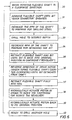
- Figure 6 is an exemplary flow diagram of the sequence which may be employed.
- Figure 7 is a schematic of a revolver used in a plugging embodiment.
- Fig. 1 shows an example of the invention in the context of a downhole formation tester that perforates a cased borehole, takes a formation sample and reseals the borehole casing.
- This cased hole tester is described in a patent application docket number 20.2634 filed concurrently with the present invention.
- the present invention is described in the context of drilling multiple holes through the casing material of a cased borehole. However, the focus of the present invention is on improving the perforating function.
- a drill bit, 1 is shown in line with the flexible driveshaft 2.
- This drill bit has a length somewhat greater than the thickness of the casing to be drilled and a diameter somewhat greater than the diameter of the flexible driveshaft 2 and coupling 4.
- the driveshaft 2 To connect the driveshaft 2 to the drill bit 1, the driveshaft 2 must be rotated in a clockwise direction as the two elements (2 and 4) come together. Pins 3 will eventually insert into grooves 5 which locks the drill bit 1 to the driveshaft 2 (as long as the driveshaft 2 maintains a clockwise rotation while drilling).
- Driving the drill via a flexible shaft allows drilling a hole to a depth greater than the diameter of the drilling apparatus.
- a translating drive system which can apply both torque and thrust to the flexible driveshaft which is needed and shown in Fig. 1.
- Fig. 3a the top assembly drawing shows a cut-away view of the block 6 with the drilling system in the starting position.
- the flexible driveshaft 2 is forced to bend ninety degrees by the two guide plates 8.
- the coupling 4 is in slidable contact with the base 9.
- the revolver 10 is attached to the base 9 via a screw and bearing (not shown). This screw and bearing allow the revolver to rotate relative to the base 9.
- Figure 3b shows a cut-away view of the block 6 with the drilling system in the process of perforating the casing.
- the flexible driveshaft 2 turns in the clockwise direction while the coupling 4 mates with the drill bit 1 as previously described. Then, using a motor-driven system (see Fig. 1), the flexshaft is advanced out into the casing, cement, and rock while creating the hole.
- Fig. 4a the top cut-away view of the block 6 shows the drilling system back into its starting position. Drill bit 1 has just finished the perforation and is now disconnected from the coupling 4. It is now required of the system to replace bit 1 with a new sharp bit (in this case bit 12).
- the piston 7 is shown to be sliding along a bore within the block 6. This movement is accomplished by using hydraulic fluid and proper and conventional valve techniques. As the piston slides from down to up, the plates 8 (which are rigidly connected to the piston) must also slide in the direction of the piston movement. The plate movement causes the base 9 to move upward as well. Because the revolver 10 is attached to the base 9, it must also slide. In addition to this linear motion, the revolver also rotates about axis 11. This rotation of the revolver is caused by a ratchet mechanism, which will be described in Fig. 5.
- the rotation of the revolver is caused by the ratchet mechanism shown in Fig. 5.
- piston 7 attached to the revolver base 9, not shown, via guide plates 8.
- the piston moves back and forth causing the guide plates, base and revolver to move in the same direction as the piston.
- the saw-toothed groove 15 is contacted by the finger 17.
- the finger 17 is attached to mount 18, which is rigidly attached to the block 6 via the probe 19.
- this contact between groove 15 and finger 17 forces the revolver 10 to rotate about axis 11.
- This rotation moves drill bit 1 (which is shown to be directly over the unseen coupling 4) counter-clockwise. In addition, it moves all the drill bits through the same rotation. This rotation allows the new drill bit 12 to ultimately align with the coupling.
- FIG. 6 is an example of the sequence of the drilling operation performed.
- driveshaft 2 and attached quick connector 4 are rotated in a clockwise manner block 30.
- the driveshaft is advanced toward the drill bit cartridge until the quick connector engages a drill bit in the cartridge that is aligned with the connector block 31.
- the RPM's (revolutions per minute) of the driveshaft are increased to prepare for the actual drilling procedure block 32.
- the drilling procedure then occurs as indicated in block 33.
- the RPM's of the driveshaft are decreased to prepare for the detachment of the drill bit block 34. While still rotating in the clockwise direction, the flexible shaft and drill bit are retracted until the bit is back in original position in the cartridge 35.
- FIG. 7 This isometric drawing shows a revolver 10 with the usual barrels 14 for the six drill bits. As previously described, these barrels are aligned about a radius around the central axis 11. In addition to this, another concentric series of six barrels 16 have been added. These barrels 16 contain the plugs that are used to reseal the perforations as needed by the tool shown in Fig. 1. However, it is important to note that the inventors recognize that the revolver can house more that just drill bits and the rotation motion can be used to index a multitude of operations.
- cartridges that can be used in this invention.
- One such cartridge can have alternating bits and plugs stacked consecutively in a magazine.
- Appropriate means can be connected to the magazine to align bits and plugs for desired drilling and plugging operations.
- revolver concepts can be implemented in embodiments other than those described herein.
- the revolver has applications in any operation or drilling system where multiple drilling operations occur during a single borehole run of a tool.
Landscapes
- Life Sciences & Earth Sciences (AREA)
- Engineering & Computer Science (AREA)
- Geology (AREA)
- Mining & Mineral Resources (AREA)
- Physics & Mathematics (AREA)
- Environmental & Geological Engineering (AREA)
- Fluid Mechanics (AREA)
- General Life Sciences & Earth Sciences (AREA)
- Geochemistry & Mineralogy (AREA)
- Soil Sciences (AREA)
- Mechanical Engineering (AREA)
- Earth Drilling (AREA)
Description
- This invention relates to the field of investigating earth formations surrounding a borehole using a flexible shaft to drill perforations through a borehole wall and into the earth formation.
- The use of a flexible shaft in drilling operations has been done for years. A number of drilling systems have been proposed where the drilling bit is driven by a flexible shaft. One such system that can be implemented in oil and gas production is described in U. S. Patent 4,658,916 (Bond). This patent utilizes a flexible drill shaft that is operable primarily from the vertical borehole when drilling in the formation in a direction that is along a generally horizontal path for a significant distance of lateral drilling away from the borehole thereby to enlarge formation contract area. U.S. patent 4,226,288 (Collins) discloses apparatus for use in a borehole for boring a side hole into the strata surrounding the borehole, the apparatus including a flexible shaft with a drill bit at its end. A worn drill bit may be replaced without selection from a magazine, the magazine being positioned to feed or drop single bits by gravity serially to a cradle which holds the bit for attachment to the shaft. U.S. patent 4,065,845 (Strom et al) discloses a device for changing bore crowns on a drill rod, the device including a rotatably mounted bore crown magazine member, and means for automatically stopping and locking the magazine member in a desired rotated position.
- Generally, the motivation for using a flexible shaft is to overcome space limitations on the drilling equipment. A flexible drilling shaft will enable the drilling of a hole which is deeper than the headroom available above the hole to be drilled. For example, in the coal mining industry, roof bolt holes are drilled into the ceiling of coal seams to a depth which can reach three times the height of the coal seem itself. In oil and gas wells it is often necessary to drill holes perpendicular to the borehole wall which are deeper than the internal diameter of the borehole. This need also applies in cased wells. In these situations, to drill such holes requires a system where a flexible drilling shaft is fed around a bend into the hole as the drilling progresses. It is important to note that the available space in these cased wells is far smaller than in previous flexible drilling shaft applications. Rather than three feet of height in coal mines, inner diameters of cased wells tend to be five inches or less. Therefore, the drilling mechanism and the flexible shaft must be much smaller in scale.
- For cased well applications, a flexible shaft, with fittings at both ends, is operated in a tubing of fixed curvature. The fittings are used to permit easy connection of the shaft to another assembly, such as the drive motor shaft and the drill bit. To facilitate drilling, the drill bit not only must be torqued so that it rotates about it's central axis (measured in "revolutions per minute" or "RPM"), but also it must be thrusted against the material to be drilled. This thrust is referred to as "weight-on-bit" or "WOB". In a drilling system that uses a flexible drilling shaft, both of these forces are typically applied to the bit through the flexshaft. An analysis of a flexible shaft in operation would yield an aggregate force balance of torques, moments and axial forces, each which would produce a deformation of the shaft.
- During drilling of the steel casing, it has been found that the shafts experience large axial compressive forces. These forces tend to induce helixing and shorten the effective length of the shafts. Also, due to the high stress, the shaft life will be shortened. It is desirable to have a long shaft life not only for system reliability, but also to increase the allowable number of drilled holes before one must retrieve the mechanism from the well and replace the worn shaft. Thus, it is important to minimize, or eliminate, the stress elements within the shaft.
- Another problem that has been recognized with such systems is the dulling of the drill bit. After perforating the steel casing, the flexible shaft must continue applying torque and thrust, albeit at lower values, while the drill bit cuts through several inches of cement. Then, in many cases, it is desirable to continue drilling into the rock, which is typically shale, limestone, or sandstone. A common component of many of these formations is quartz, a crystalline substance that is much harder than any cutting edge of typical drill bits (except for diamond, which cannot be used as it cannot drill through steel). These quartz particles dull the bit enough so that it requires higher values of torque and WOB in order to continue drilling.
- Though these increased values do not pose a problem in the cement or rock (as the initial torque and thrust were very low), they do while trying to drill steel in subsequent perforations. As previously noted, the high thrust required in order to successfully drill steel greatly shortens the life of the shaft. Once the bit dulls, the required thrust gets even larger. It has been found that after drilling only a couple of inches into sandstone, the bit is too dull to start another perforation while being driven by a flexible shaft. If one attempts to generate the required thrust, the flexible shaft is often destroyed.
- It is an object of this invention to alleviate this problem.
- An example of the invention includes a mechanism that allows for the removal and replacement of the used drill bit on the end of the flexible shaft.
- In preferred implementations, a particular type of connector is used between the flexible shaft and the bit, a method to attach (and ultimately detach) the bit to the shaft is provided, a cartridge to hold several drill bits is used, and a mechanism that indexes this cartridge for access to all of the bits is provided.
- The mechanism that connects the shaft to the drill bit needs to provide a "quick" connection between the bit and shaft. One connection mechanism is commonly referred to as a "bayonet-style" connector. Similar connections are used to attach bayonets to rifles or to connect wires to various stereo components. As the flexible shaft advances toward the backside of the drill bit (which is still held in the cartridge), the shaft is slowly rotated normally in the clockwise direction. This rotation allows the bayonet-style connector to engage. Now connected, the shaft and bit advance toward the material (usually casing) to begin drilling the hole. When the drilling procedure is complete, the flexible shaft is retracted (still turning clockwise) until the dulled bit is back inside the cartridge. At this point, the motor turning the flexible shaft is reversed, and the shaft begins turning counter-clockwise. This allows the bayonet-style connector to disengage, which leaves the used bit in its original place in the cartridge.
- The cartridge that holds the bits can be of many different designs. One of the designs that fits best into the geometric constraints of the drilling system is referred to as the "revolver". Much like the cylindrical-shaped cartridge used in a "six-shooter" pistol, this revolver holds at least six drill bits aligned about a radius. After each bit is used and is disengaged from the flexible shaft, the revolver is rotated so that a new bit aligns with the flexible shaft, ready for the next drilling operation. This process can continue until all of the bits within the revolver have been used.
- In order to know how many bits have been used and the number of unused bits that remain, there is a need to index the cartridge. There are many ways to index the cartridge, or in this case, the revolver. One of the designs that fits best into the geometric constraints is referred to as the "ratchet" mechanism. After each hole is drilled and the dulled drill bit is deposited into the revolver, a piston is hydraulic actuated. This piston is connected to the base on which the revolver is positioned. As the piston moves in a direction away from the revolver, so does the base and so does the revolver move in that same direction. As the revolver moves, a rotation mechanism causes the revolver to rotate. One such mechanism is a springloaded "finger" engages a saw-toothed groove (in the side of the revolver) and causes the revolver to rotate. The mechanism is designed so that the revolver rotates exactly the amount needed for the next drill bit to align with the flexible shaft. Ball detents in the base can be used to account for any tolerancing errors. In order to reset the ratchet system, the piston is moved back to the previous revolver position. This time, however, the finger slides up the ramp of the saw-tooth groove and does not create enough force to cause any counter rotation of the revolver.
- Embodiments of the system of the invention are simple, robust, and can be built into the small diameter tool package capable of passing into the internal diameter of the casing. It constitutes a great improvement over previous flexible shaft drilling systems whereby a single bit was used and, due to the short life of the shaft, only a couple of successive drilling operations could be performed before failure.
- Figure 1 is a schematic of a formation testing apparatus that is used in a cased borehole environment.
- Figure 2 is an isometric drawing of the drill bit, bayonet-style quick connector and the end of the flexible driveshaft.
- Figure 3a is an isometric assembly drawing that illustrates the interaction of the flexible driveshaft, drill bits, and revolver with the drilling system in the starting position.
- Figure 3b is an isometric assembly drawing that illustrates the interaction of the flexible driveshaft, drill bits, and revolver with the flexible shaft extended.
- Figure 4a is an isometric assembly drawing that illustrates how the hydraulic piston moves the base and revolver with the piston being in a more downward position.
- Figure 4b is an isometric assembly drawing that illustrates how the hydraulic piston moves the base and revolver with the piston being in a more central position.
- Figure 4c is an isometric assembly drawing that illustrates how the hydraulic piston moves the base and revolver with the piston being in a more upward position.
- Figure 5 is a top view (cross-section) of the assembly that illustrates how the ratchet system causes the rotation of the revolver.
- Figure 6 is an exemplary flow diagram of the sequence which may be employed.
- Figure 7 is a schematic of a revolver used in a plugging embodiment.
- Fig. 1 shows an example of the invention in the context of a downhole formation tester that perforates a cased borehole, takes a formation sample and reseals the borehole casing. This cased hole tester is described in a patent application docket number 20.2634 filed concurrently with the present invention. The present invention is described in the context of drilling multiple holes through the casing material of a cased borehole. However, the focus of the present invention is on improving the perforating function.
- In Fig. 2, a drill bit, 1 is shown in line with the
flexible driveshaft 2. This drill bit has a length somewhat greater than the thickness of the casing to be drilled and a diameter somewhat greater than the diameter of theflexible driveshaft 2 andcoupling 4. To connect thedriveshaft 2 to thedrill bit 1, thedriveshaft 2 must be rotated in a clockwise direction as the two elements (2 and 4) come together.Pins 3 will eventually insert intogrooves 5 which locks thedrill bit 1 to the driveshaft 2 (as long as thedriveshaft 2 maintains a clockwise rotation while drilling). Driving the drill via a flexible shaft allows drilling a hole to a depth greater than the diameter of the drilling apparatus. A translating drive system which can apply both torque and thrust to the flexible driveshaft which is needed and shown in Fig. 1. - In Fig. 3a, the top assembly drawing shows a cut-away view of the
block 6 with the drilling system in the starting position. Theflexible driveshaft 2 is forced to bend ninety degrees by the twoguide plates 8. Thecoupling 4 is in slidable contact with thebase 9. Therevolver 10 is attached to thebase 9 via a screw and bearing (not shown). This screw and bearing allow the revolver to rotate relative to thebase 9. In this version of the assembly, there is room for six drill bits (1 and 12 shown) aligned about a radius around the center of the revolver. Note thatdrill bit 1 is aligned with thecoupling 4, ready for attachment.Drill bit 12 is not currently aligned with the coupling. - Figure 3b shows a cut-away view of the
block 6 with the drilling system in the process of perforating the casing. Theflexible driveshaft 2 turns in the clockwise direction while thecoupling 4 mates with thedrill bit 1 as previously described. Then, using a motor-driven system (see Fig. 1), the flexshaft is advanced out into the casing, cement, and rock while creating the hole. - In Fig. 4a, the top cut-away view of the
block 6 shows the drilling system back into its starting position.Drill bit 1 has just finished the perforation and is now disconnected from thecoupling 4. It is now required of the system to replacebit 1 with a new sharp bit (in this case bit 12). - In Fig. 4b, the
piston 7 is shown to be sliding along a bore within theblock 6. This movement is accomplished by using hydraulic fluid and proper and conventional valve techniques. As the piston slides from down to up, the plates 8 (which are rigidly connected to the piston) must also slide in the direction of the piston movement. The plate movement causes thebase 9 to move upward as well. Because therevolver 10 is attached to thebase 9, it must also slide. In addition to this linear motion, the revolver also rotates aboutaxis 11. This rotation of the revolver is caused by a ratchet mechanism, which will be described in Fig. 5. - In Fig. 4c, the sliding motion of
piston 7 through the bore withinblock 6 is complete. Note that therevolver 10 has also completed its rotation, wherebydrill bit 12 is now aligned with thecoupling 4. Hidden behind drill bit 12 (and not shown in this view) is the useddull drill bit 1, which is no longer aligned with thecoupling 4. In order to ready the system for the next perforation,piston 7 must be fully reset back to its position shown in Fig. 4a. - As previously mentioned, the rotation of the revolver is caused by the ratchet mechanism shown in Fig. 5. In this cross-sectional top view of the revolver and ratchet system,
piston 7 attached to therevolver base 9, not shown, viaguide plates 8. The piston moves back and forth causing the guide plates, base and revolver to move in the same direction as the piston. As therevolver 10 begins the linear motion as indicated by the arrow, the saw-toothed groove 15 is contacted by the finger 17. The finger 17 is attached to mount 18, which is rigidly attached to theblock 6 via theprobe 19. As therevolver 10 continues the linear motion, this contact betweengroove 15 and finger 17 forces therevolver 10 to rotate aboutaxis 11. This rotation moves drill bit 1 (which is shown to be directly over the unseen coupling 4) counter-clockwise. In addition, it moves all the drill bits through the same rotation. This rotation allows thenew drill bit 12 to ultimately align with the coupling. - As shown in Fig. 5, there can also be another
finger 20 positioned at the bottom of the slot inprobe 19. When thisfinger 20 is added to the ratchet mechanism, the design constraints are somewhat simplified. That is rather than relying on finger 17 to fully rotate therevolver 10, this upgraded system only requires finger 17 to rotate therevolver 10 halfway. On the return linear motion (from the right to the left),finger 20 contacts another saw-toothed groove, and finishes the counter-clockwise rotation so that thenew drill bit 12 is ultimately aligned with thecoupling 4. - Figure 6 is an example of the sequence of the drilling operation performed. To begin the operation,
driveshaft 2 and attachedquick connector 4 are rotated in aclockwise manner block 30. The driveshaft is advanced toward the drill bit cartridge until the quick connector engages a drill bit in the cartridge that is aligned with theconnector block 31. After the connector engages the drill bit, the RPM's (revolutions per minute) of the driveshaft are increased to prepare for the actualdrilling procedure block 32. The drilling procedure then occurs as indicated inblock 33. At the completion of the drilling procedure, the RPM's of the driveshaft are decreased to prepare for the detachment of thedrill bit block 34. While still rotating in the clockwise direction, the flexible shaft and drill bit are retracted until the bit is back in original position in thecartridge 35. Now that the drill bit is in its original position, the rotation of the driveshaft is reversed until the drill bit detached from theshaft 36. The next step is to retract the flexible shaft into thetool 37 to permit the rotating of therevolver 38. The revolver is rotated via a hydraulically activatedpiston 7. The revolver is rotated as shown in Fig. 5. Once the revolver is rotated and the next drill bit to be used is aligned with theflexible shaft 2, the hydraulically actuated piston is returned to itsoriginal position 39. Now the system is ready to repeat the process and drill anotherhole 40. - Another embodiment is shown in Fig. 7. This isometric drawing shows a
revolver 10 with theusual barrels 14 for the six drill bits. As previously described, these barrels are aligned about a radius around thecentral axis 11. In addition to this, another concentric series of sixbarrels 16 have been added. Thesebarrels 16 contain the plugs that are used to reseal the perforations as needed by the tool shown in Fig. 1. However, it is important to note that the inventors recognize that the revolver can house more that just drill bits and the rotation motion can be used to index a multitude of operations. - Although a revolver type cartridge embodiment is described herein, there are types of cartridges that can be used in this invention. One such cartridge can have alternating bits and plugs stacked consecutively in a magazine. Appropriate means can be connected to the magazine to align bits and plugs for desired drilling and plugging operations.
- In addition, the revolver concepts can be implemented in embodiments other than those described herein. The revolver has applications in any operation or drilling system where multiple drilling operations occur during a single borehole run of a tool.
- The method and apparatus of the invention provide a significant advantage over the prior art. The invention has been described in connection with the preferred embodiments. However, the invention is not limited thereto. Changes, variations and modifications to the basic design may be made without departing from the inventive concept in this invention. In addition, these changes, variations and modifications would be obvious to those skilled in the art having the benefit of the foregoing teachings contained in this application. All such changes, variations and modifications are intended to be within the scope of the invention which is limited by the following claims.
Claims (16)
- A drilling system adapted to be positioned in a borehole traversing an earth formation for drilling through a material from the borehole, the drilling system comprising:a) a plurality of drill bits (1, 12) to be brought into contact with the material;b) a cartridge (10) for storing said drill bits when not in use;c) a flexible shaft (2) having the capability of engaging any of said drill bits (1, 12);d) an actuator connected to said flexible shaft (2) that rotates said flexible shaft and engages one of said drill bits (1, 12) during the drilling process; and characterised bye) said cartridge (10) having a plurality of chambers (14, 16) in which said drill bits are stored when not in use; andf) linearly-actuated means (4, 6, 7, 9, 15, 17) for exchanging any of said drill bits (1, 12) between each of a succession of drilling perforations into the material.
- The drilling system of claim 1, wherein said cartridge is a revolver (10).
- The drilling system of claim 1, wherein said linearly-actuated drill bit exchanging means comprises:a connector (4) disposed between said shaft (2) and at least one of said drill bits (1, 12); anda means (7, 9, 15, 17) for rotating said cartridge (10) so that successive bits can be connected to said shaft (2).
- The drilling system of claim 1, further comprising a material such as rubber in each of said plurality of chambers (14, 16) to restrict bit movement when the bits (1, 12) are stored in the chambers.
- The drilling system of claim 3, wherein said rotating means comprises:a base (9) attached to said cartridge (10), the attachment permitting relative rotation therebetween; anda piston (7) for linearly-actuating the base.
- The drilling system of claim 5, wherein said cartridge (10) has an outer surface containing recesses (15) to facilitate conversion of the linear motion of said cartridge (10), provided via linear actuation of the base (9) by the piston (7), into rotation of said cartridge (10) about its axis relative to the base (9).
- The drilling system of claim 6, further comprising a finger (17) that engages said cartridge (10) via the recesses (15) when the cartridge is moved linearly relative to the finger (17) thereby inducing rotation of said cartridge (10) about its axis.
- The drilling system of claim 7, wherein the finger (17) has a lip portion that engages the cartridge (10).
- The drilling system of claim 7, further comprising a second finger (20) that engages said cartridge (10) via the recesses (15) when the cartridge is moved linearly relative to the second finger (20) thereby inducing further rotation of said cartridge (10) about its axis.
- A method for drilling through a material using a drilling system that includes a plurality of drill bits (1, 12), a flexible drilling shaft (2), and a cartridge (10) for storing the drill bits, the method comprising the steps of:a) engaging a drill bit (1) with the shaft (2);b) moving the shaft-engaged drill bit into contact with the material to be drilled;c) rotating the shaft (2) to induce drilling with the drill bit (1) through the material; andd) replacing the bit (1) with a new drill bit (12) from the cartridge (10); the method being characterized in that step d) includes:e) disengaging the drill bit (1) from the shaft (2) and storing the bit (1) in the cartridge;f) applying a force to the cartridge (10) to induce linear movement of the cartridge, whereby a new drill bit (12) is positioned for engagement with the shaft (2).
- The method of claim 10, wherein step a) includes rotating the shaft (2) to engage the shaft with the drill bit (1).
- The method of claim 10, wherein step f) includes:moving the cartridge (10) linearly from an initial position such that the outer surface thereof engages a stationary device causing the cartridge to rotate about its axis; andreturning the cartridge to its initial position.
- A flexible shaft drilling system for use in a borehole traversing an earth formation for drilling through a material from said borehole, the system comprising:a) a plurality of drill bits (1,12) for drilling through said material;b) means (10) for holding said plurality of drill bits when said bits are not in use;c) actuating means for rotating said drill bit during a drilling operation;d) a flexible shaft (2) having one end thereof connected to said actuating means and the other end connected to means for connecting a drill bit to be used in drilling through a material; and characterised bye) linearly-actuated means (4, 6, 7, 9, 15, 17) for removal and replacement of a used drill bit connected to said flexible shaft by any of said plurality drill bits.
- The drilling system of claim 13 wherein said means for holding has a plurality of chambers, each chamber adapted to hold one drill bit.
- The drilling system of claim 14 wherein the means for holding is a revolver.
- The drilling system of any one of claims 13 to 15 wherein said holding means further holds a plurality of plugs for plugging drill created perforations in said material.
Applications Claiming Priority (2)
| Application Number | Priority Date | Filing Date | Title |
|---|---|---|---|
| US602485 | 1996-02-20 | ||
| US08/602,485 US5746279A (en) | 1996-02-20 | 1996-02-20 | Method and apparatus for changing bits while drilling with a flexible shaft |
Publications (2)
| Publication Number | Publication Date |
|---|---|
| EP0791721A1 EP0791721A1 (en) | 1997-08-27 |
| EP0791721B1 true EP0791721B1 (en) | 2002-07-31 |
Family
ID=24411535
Family Applications (1)
| Application Number | Title | Priority Date | Filing Date |
|---|---|---|---|
| EP97301088A Expired - Lifetime EP0791721B1 (en) | 1996-02-20 | 1997-02-20 | Apparatus and method for drilling with a flexible shaft |
Country Status (6)
| Country | Link |
|---|---|
| US (1) | US5746279A (en) |
| EP (1) | EP0791721B1 (en) |
| CA (1) | CA2197960C (en) |
| DE (1) | DE69714315T2 (en) |
| MX (1) | MX9701298A (en) |
| NO (1) | NO313152B1 (en) |
Cited By (1)
| Publication number | Priority date | Publication date | Assignee | Title |
|---|---|---|---|---|
| US7380599B2 (en) | 2004-06-30 | 2008-06-03 | Schlumberger Technology Corporation | Apparatus and method for characterizing a reservoir |
Families Citing this family (25)
| Publication number | Priority date | Publication date | Assignee | Title |
|---|---|---|---|---|
| US6766854B2 (en) | 1997-06-02 | 2004-07-27 | Schlumberger Technology Corporation | Well-bore sensor apparatus and method |
| US6637508B2 (en) | 2001-10-22 | 2003-10-28 | Varco I/P, Inc. | Multi-shot tubing perforator |
| EP1388615A1 (en) * | 2002-08-06 | 2004-02-11 | ABB Immobilien AG | Method and apparatus for soil examination |
| RU2251618C2 (en) * | 2003-03-27 | 2005-05-10 | Открытое акционерное общество Научно-производственное предприятие "Научно-исследовательский и проектно-конструкторский институт геофизических исследований геологоразведочных скважин (ОАО НПП "ВНИИГИС") | Device for extracting sample out of borehole |
| US7347262B2 (en) * | 2004-06-18 | 2008-03-25 | Schlumberger Technology Corporation | Downhole sampling tool and method for using same |
| DE102004045404A1 (en) * | 2004-09-18 | 2006-03-30 | Klemm Bohrtechnik Zweigniederlassung Der Bauer Maschinen Gmbh | Drilling rig with drill tool magazine |
| EP2065553B1 (en) | 2007-11-30 | 2013-12-25 | Services Pétroliers Schlumberger | System and method for drilling lateral boreholes |
| EP2065554B1 (en) * | 2007-11-30 | 2014-04-02 | Services Pétroliers Schlumberger | System and method for drilling and completing lateral boreholes |
| US8474615B2 (en) * | 2007-12-12 | 2013-07-02 | Richard Vernon Kernodle, JR. | Retention dual use bit holder |
| WO2010008684A2 (en) * | 2008-07-15 | 2010-01-21 | Schlumberger Canada Limited | Apparatus and methods for characterizing a reservoir |
| US8408296B2 (en) | 2010-08-18 | 2013-04-02 | Schlumberger Technology Corporation | Methods for borehole measurements of fracturing pressures |
| US8397817B2 (en) * | 2010-08-18 | 2013-03-19 | Schlumberger Technology Corporation | Methods for downhole sampling of tight formations |
| US9377265B2 (en) | 2013-12-04 | 2016-06-28 | Claire C. Marvin | Gun barrel cleaning device |
| US9964377B2 (en) | 2013-12-04 | 2018-05-08 | Claire C. Marvin | Gun barrel cleaning device |
| USD747165S1 (en) | 2014-06-05 | 2016-01-12 | Charles Amash Imports, Inc. | Magnetic socket holder |
| NO340765B1 (en) * | 2014-08-21 | 2017-06-12 | Agat Tech As | Drilling module for radial drilling in a well, as well as drilling tools comprising the drilling module |
| DK3502411T3 (en) * | 2014-08-21 | 2021-05-03 | Agat Tech As | Anchoring module for well tools |
| CA2971322C (en) * | 2017-06-19 | 2018-05-15 | Remuda Energy Solutions Ltd. | Apparatus and method for cutting a tubular |
| US11313225B2 (en) * | 2020-08-27 | 2022-04-26 | Saudi Arabian Oil Company | Coring method and apparatus |
| US11332997B2 (en) * | 2020-09-01 | 2022-05-17 | Saudi Arabian Oil Company | Downhole drill-inject and plug tool |
| RU2745088C1 (en) * | 2020-09-14 | 2021-03-19 | Георгий Николаевич Филиди | Device for deep well perforation |
| US12241370B1 (en) * | 2021-05-13 | 2025-03-04 | National Technology & Engineering Solutions Of Sandia, Llc | Systems and methods for automated drilling of high aspect ratio, small diameter holes in remote, confined spaces |
| US11802827B2 (en) | 2021-12-01 | 2023-10-31 | Saudi Arabian Oil Company | Single stage MICP measurement method and apparatus |
| US12049807B2 (en) | 2021-12-02 | 2024-07-30 | Saudi Arabian Oil Company | Removing wellbore water |
| US20250020824A1 (en) * | 2023-07-14 | 2025-01-16 | Halliburton Energy Services, Inc. | Through casing sensor placement |
Family Cites Families (8)
| Publication number | Priority date | Publication date | Assignee | Title |
|---|---|---|---|---|
| US2392683A (en) * | 1943-06-28 | 1946-01-08 | Lane Wells Co | Side wall sampling tool |
| US3976149A (en) * | 1972-02-08 | 1976-08-24 | Linden-Alimak Ab | Rock drill equipment having a mechanized drill bit exchange |
| FI56575C (en) * | 1974-04-23 | 1980-02-11 | Tampella Oy Ab | ANORDING FOR THE PURPOSE OF BORK RONOR PAO EN BORRSTAONG |
| US4226288A (en) * | 1978-05-05 | 1980-10-07 | California Institute Of Technology | Side hole drilling in boreholes |
| SU794197A1 (en) * | 1979-04-16 | 1981-01-07 | Краснодарский Государственный Науч-Ho-Исследовательский И Проектныйинститут Нефтяной Промышленности | Formation opening-up device |
| US4658916A (en) * | 1985-09-13 | 1987-04-21 | Les Bond | Method and apparatus for hydrocarbon recovery |
| DK597088A (en) * | 1987-10-27 | 1989-04-28 | Geissler & Kuper Gmbh | CLUTCH NAMELY TO A DIAMOND DRILL CHRONICLE WITH SCRAP THREATS AND CIRCULAR WIND CONNECTION |
| US5195588A (en) * | 1992-01-02 | 1993-03-23 | Schlumberger Technology Corporation | Apparatus and method for testing and repairing in a cased borehole |
-
1996
- 1996-02-20 US US08/602,485 patent/US5746279A/en not_active Expired - Lifetime
-
1997
- 1997-02-19 NO NO19970771A patent/NO313152B1/en not_active IP Right Cessation
- 1997-02-19 CA CA002197960A patent/CA2197960C/en not_active Expired - Lifetime
- 1997-02-20 DE DE69714315T patent/DE69714315T2/en not_active Expired - Lifetime
- 1997-02-20 EP EP97301088A patent/EP0791721B1/en not_active Expired - Lifetime
- 1997-02-20 MX MX9701298A patent/MX9701298A/en unknown
Cited By (1)
| Publication number | Priority date | Publication date | Assignee | Title |
|---|---|---|---|---|
| US7380599B2 (en) | 2004-06-30 | 2008-06-03 | Schlumberger Technology Corporation | Apparatus and method for characterizing a reservoir |
Also Published As
| Publication number | Publication date |
|---|---|
| NO970771L (en) | 1997-08-21 |
| DE69714315D1 (en) | 2002-09-05 |
| US5746279A (en) | 1998-05-05 |
| NO970771D0 (en) | 1997-02-19 |
| DE69714315T2 (en) | 2003-03-20 |
| MX9701298A (en) | 1998-04-30 |
| CA2197960C (en) | 2003-12-09 |
| NO313152B1 (en) | 2002-08-19 |
| EP0791721A1 (en) | 1997-08-27 |
| CA2197960A1 (en) | 1997-08-21 |
Similar Documents
| Publication | Publication Date | Title |
|---|---|---|
| US5746279A (en) | Method and apparatus for changing bits while drilling with a flexible shaft | |
| MXPA97001298A (en) | Method and apparatus to change bits while drilling with a flexi axle | |
| AU721128B2 (en) | Method and apparatus for drilling with a flexible shaft while using hydraulic assistance | |
| US7111685B2 (en) | Downhole sampling apparatus and method | |
| CA2238782C (en) | Method and apparatus for radially drilling through well casing and formation | |
| US4658916A (en) | Method and apparatus for hydrocarbon recovery | |
| US5350015A (en) | Rotary downhole cutting tool | |
| NO325658B1 (en) | Method, apparatus and system for milling casing using coiled tubing | |
| US8839864B2 (en) | Casing cutter | |
| US10724304B2 (en) | Cutting element assemblies and downhole tools comprising rotatable and removable cutting elements and related methods | |
| US4466495A (en) | Pressure core barrel for the sidewall coring tool | |
| GB2216926A (en) | Drilling and lining a borehole | |
| NO335591B1 (en) | Procedure for increasing the productivity of a well | |
| MX2013005077A (en) | Casing spears and related systems and methods. | |
| CN111032992B (en) | Cutting element assemblies and downhole tools including rotatable cutting elements and related methods | |
| CN115788300A (en) | Continuous rotating sliding drilling method | |
| EP3736406B1 (en) | Tubular cutting tool | |
| EP0028121A1 (en) | Improvements relating to downhole shearers | |
| US6786282B2 (en) | Milling apparatus and method for a well | |
| US11946321B2 (en) | Cutting element assemblies and downhole tools comprising rotatable and removable cutting elements and related methods | |
| RU2286442C1 (en) | Method for deep casing pipe perforation and perforation device for above method realization | |
| US12497850B2 (en) | Casing erosion tool with pivotable jetting sub | |
| US12312888B2 (en) | External intervention downhole drilling and workover tool | |
| EP3931421A1 (en) | High speed drilling system and methods of using same |
Legal Events
| Date | Code | Title | Description |
|---|---|---|---|
| PUAI | Public reference made under article 153(3) epc to a published international application that has entered the european phase |
Free format text: ORIGINAL CODE: 0009012 |
|
| AK | Designated contracting states |
Kind code of ref document: A1 Designated state(s): DE FR GB IT |
|
| 17P | Request for examination filed |
Effective date: 19980204 |
|
| 17Q | First examination report despatched |
Effective date: 20001009 |
|
| GRAG | Despatch of communication of intention to grant |
Free format text: ORIGINAL CODE: EPIDOS AGRA |
|
| GRAG | Despatch of communication of intention to grant |
Free format text: ORIGINAL CODE: EPIDOS AGRA |
|
| GRAH | Despatch of communication of intention to grant a patent |
Free format text: ORIGINAL CODE: EPIDOS IGRA |
|
| GRAH | Despatch of communication of intention to grant a patent |
Free format text: ORIGINAL CODE: EPIDOS IGRA |
|
| GRAA | (expected) grant |
Free format text: ORIGINAL CODE: 0009210 |
|
| AK | Designated contracting states |
Kind code of ref document: B1 Designated state(s): DE FR GB IT |
|
| REG | Reference to a national code |
Ref country code: GB Ref legal event code: FG4D |
|
| REF | Corresponds to: |
Ref document number: 69714315 Country of ref document: DE Date of ref document: 20020905 |
|
| ET | Fr: translation filed | ||
| PLBE | No opposition filed within time limit |
Free format text: ORIGINAL CODE: 0009261 |
|
| STAA | Information on the status of an ep patent application or granted ep patent |
Free format text: STATUS: NO OPPOSITION FILED WITHIN TIME LIMIT |
|
| 26N | No opposition filed |
Effective date: 20030506 |
|
| PGFP | Annual fee paid to national office [announced via postgrant information from national office to epo] |
Ref country code: IT Payment date: 20080227 Year of fee payment: 12 |
|
| PG25 | Lapsed in a contracting state [announced via postgrant information from national office to epo] |
Ref country code: IT Free format text: LAPSE BECAUSE OF NON-PAYMENT OF DUE FEES Effective date: 20090220 |
|
| REG | Reference to a national code |
Ref country code: FR Ref legal event code: PLFP Year of fee payment: 20 |
|
| PGFP | Annual fee paid to national office [announced via postgrant information from national office to epo] |
Ref country code: DE Payment date: 20160216 Year of fee payment: 20 |
|
| PGFP | Annual fee paid to national office [announced via postgrant information from national office to epo] |
Ref country code: FR Payment date: 20160108 Year of fee payment: 20 Ref country code: GB Payment date: 20160217 Year of fee payment: 20 |
|
| REG | Reference to a national code |
Ref country code: DE Ref legal event code: R071 Ref document number: 69714315 Country of ref document: DE |
|
| REG | Reference to a national code |
Ref country code: GB Ref legal event code: PE20 Expiry date: 20170219 |
|
| PG25 | Lapsed in a contracting state [announced via postgrant information from national office to epo] |
Ref country code: GB Free format text: LAPSE BECAUSE OF EXPIRATION OF PROTECTION Effective date: 20170219 |