EP0791649B1 - Flask vent and method of making same - Google Patents
Flask vent and method of making same Download PDFInfo
- Publication number
- EP0791649B1 EP0791649B1 EP97200350A EP97200350A EP0791649B1 EP 0791649 B1 EP0791649 B1 EP 0791649B1 EP 97200350 A EP97200350 A EP 97200350A EP 97200350 A EP97200350 A EP 97200350A EP 0791649 B1 EP0791649 B1 EP 0791649B1
- Authority
- EP
- European Patent Office
- Prior art keywords
- closure
- filter membrane
- passageway
- container
- seal
- Prior art date
- Legal status (The legal status is an assumption and is not a legal conclusion. Google has not performed a legal analysis and makes no representation as to the accuracy of the status listed.)
- Expired - Lifetime
Links
- 238000004519 manufacturing process Methods 0.000 title description 4
- 239000012528 membrane Substances 0.000 claims description 37
- 230000002093 peripheral effect Effects 0.000 claims description 23
- 238000007789 sealing Methods 0.000 claims description 18
- 244000005700 microbiome Species 0.000 claims description 15
- 239000000463 material Substances 0.000 claims description 14
- 238000000465 moulding Methods 0.000 claims description 11
- 238000000034 method Methods 0.000 claims description 7
- 239000012530 fluid Substances 0.000 claims description 6
- 238000003780 insertion Methods 0.000 claims description 4
- 230000037431 insertion Effects 0.000 claims description 4
- 239000012858 resilient material Substances 0.000 claims description 4
- 238000004891 communication Methods 0.000 claims description 3
- 230000002209 hydrophobic effect Effects 0.000 claims description 2
- 239000007789 gas Substances 0.000 description 6
- QVGXLLKOCUKJST-UHFFFAOYSA-N atomic oxygen Chemical compound [O] QVGXLLKOCUKJST-UHFFFAOYSA-N 0.000 description 4
- 230000036512 infertility Effects 0.000 description 4
- 230000002906 microbiologic effect Effects 0.000 description 4
- 239000001301 oxygen Substances 0.000 description 4
- 229910052760 oxygen Inorganic materials 0.000 description 4
- 238000011109 contamination Methods 0.000 description 3
- 230000007812 deficiency Effects 0.000 description 3
- 239000007788 liquid Substances 0.000 description 3
- 229920001296 polysiloxane Polymers 0.000 description 3
- 229920000742 Cotton Polymers 0.000 description 2
- 238000004026 adhesive bonding Methods 0.000 description 2
- 239000011521 glass Substances 0.000 description 2
- -1 polypropylenes Polymers 0.000 description 2
- 229920001343 polytetrafluoroethylene Polymers 0.000 description 2
- RZVAJINKPMORJF-UHFFFAOYSA-N Acetaminophen Chemical compound CC(=O)NC1=CC=C(O)C=C1 RZVAJINKPMORJF-UHFFFAOYSA-N 0.000 description 1
- YCKRFDGAMUMZLT-UHFFFAOYSA-N Fluorine atom Chemical compound [F] YCKRFDGAMUMZLT-UHFFFAOYSA-N 0.000 description 1
- 229920001410 Microfiber Polymers 0.000 description 1
- 239000004952 Polyamide Substances 0.000 description 1
- 239000004743 Polypropylene Substances 0.000 description 1
- 241000219289 Silene Species 0.000 description 1
- 239000000356 contaminant Substances 0.000 description 1
- 229920001577 copolymer Polymers 0.000 description 1
- 238000013461 design Methods 0.000 description 1
- 238000011161 development Methods 0.000 description 1
- 238000001914 filtration Methods 0.000 description 1
- 229910052731 fluorine Inorganic materials 0.000 description 1
- 239000011737 fluorine Substances 0.000 description 1
- 229920002313 fluoropolymer Polymers 0.000 description 1
- 239000011159 matrix material Substances 0.000 description 1
- 239000002184 metal Substances 0.000 description 1
- 238000009629 microbiological culture Methods 0.000 description 1
- 239000003658 microfiber Substances 0.000 description 1
- 229920003052 natural elastomer Polymers 0.000 description 1
- 229920001194 natural rubber Polymers 0.000 description 1
- 239000013618 particulate matter Substances 0.000 description 1
- 239000004033 plastic Substances 0.000 description 1
- 229920002492 poly(sulfone) Polymers 0.000 description 1
- 229920002647 polyamide Polymers 0.000 description 1
- 229920000098 polyolefin Polymers 0.000 description 1
- 229920001155 polypropylene Polymers 0.000 description 1
- 239000011148 porous material Substances 0.000 description 1
- 230000001902 propagating effect Effects 0.000 description 1
- 239000005297 pyrex Substances 0.000 description 1
- 239000011347 resin Substances 0.000 description 1
- 229920005989 resin Polymers 0.000 description 1
- 238000004513 sizing Methods 0.000 description 1
- 229910001220 stainless steel Inorganic materials 0.000 description 1
- 239000010935 stainless steel Substances 0.000 description 1
- 238000004659 sterilization and disinfection Methods 0.000 description 1
- 229920003051 synthetic elastomer Polymers 0.000 description 1
- 239000005061 synthetic rubber Substances 0.000 description 1
Images
Classifications
-
- C—CHEMISTRY; METALLURGY
- C12—BIOCHEMISTRY; BEER; SPIRITS; WINE; VINEGAR; MICROBIOLOGY; ENZYMOLOGY; MUTATION OR GENETIC ENGINEERING
- C12M—APPARATUS FOR ENZYMOLOGY OR MICROBIOLOGY; APPARATUS FOR CULTURING MICROORGANISMS FOR PRODUCING BIOMASS, FOR GROWING CELLS OR FOR OBTAINING FERMENTATION OR METABOLIC PRODUCTS, i.e. BIOREACTORS OR FERMENTERS
- C12M29/00—Means for introduction, extraction or recirculation of materials, e.g. pumps
- C12M29/20—Degassing; Venting; Bubble traps
-
- C—CHEMISTRY; METALLURGY
- C12—BIOCHEMISTRY; BEER; SPIRITS; WINE; VINEGAR; MICROBIOLOGY; ENZYMOLOGY; MUTATION OR GENETIC ENGINEERING
- C12M—APPARATUS FOR ENZYMOLOGY OR MICROBIOLOGY; APPARATUS FOR CULTURING MICROORGANISMS FOR PRODUCING BIOMASS, FOR GROWING CELLS OR FOR OBTAINING FERMENTATION OR METABOLIC PRODUCTS, i.e. BIOREACTORS OR FERMENTERS
- C12M23/00—Constructional details, e.g. recesses, hinges
- C12M23/02—Form or structure of the vessel
- C12M23/08—Flask, bottle or test tube
-
- C—CHEMISTRY; METALLURGY
- C12—BIOCHEMISTRY; BEER; SPIRITS; WINE; VINEGAR; MICROBIOLOGY; ENZYMOLOGY; MUTATION OR GENETIC ENGINEERING
- C12M—APPARATUS FOR ENZYMOLOGY OR MICROBIOLOGY; APPARATUS FOR CULTURING MICROORGANISMS FOR PRODUCING BIOMASS, FOR GROWING CELLS OR FOR OBTAINING FERMENTATION OR METABOLIC PRODUCTS, i.e. BIOREACTORS OR FERMENTERS
- C12M23/00—Constructional details, e.g. recesses, hinges
- C12M23/38—Caps; Covers; Plugs; Pouring means
-
- Y—GENERAL TAGGING OF NEW TECHNOLOGICAL DEVELOPMENTS; GENERAL TAGGING OF CROSS-SECTIONAL TECHNOLOGIES SPANNING OVER SEVERAL SECTIONS OF THE IPC; TECHNICAL SUBJECTS COVERED BY FORMER USPC CROSS-REFERENCE ART COLLECTIONS [XRACs] AND DIGESTS
- Y10—TECHNICAL SUBJECTS COVERED BY FORMER USPC
- Y10S—TECHNICAL SUBJECTS COVERED BY FORMER USPC CROSS-REFERENCE ART COLLECTIONS [XRACs] AND DIGESTS
- Y10S215/00—Bottles and jars
- Y10S215/03—Medical
Definitions
- the present invention relates to a closure. More specifically, the present invention relates to a closure for allowing sterile gas exchange therethrough.
- closure devices for covering microbiological vessels, such as flasks, has been a widely accepted and longly used practice in microbiology. Closures are used in order to prevent the contamination of microorganisms being cultured or stored within the flasks by airborne contaminates or particulate matter. Additionally, these closures have been used to prevent the escape of microorganisms being cultured or stored in the flasks from being released from the flasks where they can become airborne and become contaminates themselves.
- microorganisms or cultures must be grown under sterile conditions.
- closures have been designed to accommodate the specific growth requirements for each of these types of microorganisms.
- aerobic microorganisms are only able to live in the presence of oxygen whereas anaerobic microorganisms are capable of growing, and in some circumstances are unable to grow, in the presence of oxygen. Therefore, for anaerobic organisms a closure may be required which is capable of maintaining sterile conditions within the interior of the flask or vessel by preventing the introduction of contaminating microorganisms while at the same time preventing the entrance of oxygen into the container or vessel.
- microbiological vessel or flask closure Another requirement for a microbiological vessel or flask closure is that while maintaining the sterility of the microorganisms or cultures being grown therein, the closure should provide free access into the container or flask to facilitate the addition or removal of contents from the vessel or flask, such as sterile removal of microbiological culture from the vessel or flask.
- cotton or gauze was formed into a plug and was inserted into the opening of a container or flask. These cotton or gauze plugs serve the general purpose of preventing contamination of the container or flask while simultaneously permitting the free exchange of oxygen with the atmosphere.
- This type of closure has many deficiencies such as it can be difficult to resterilise the plug for subsequent use and after repeated usage, this type of plug tends to readily decompose.
- US5037754 discloses a culture vessel, at least part of which comprises a film of a gas permeable fluorine-containing melt processable resin and US5180073 discloses a cap for a flask with a permeable section in the top portion of the cap for enabling air exchange between the flask and the environment.
- closure assembly for use with microbiological containers or flasks in which the closure assembly includes a filter membrane and a seal which allows for creating an air and fluid tight seal between the closure and the container or flask and in which the closure assembly can be produced in a one step process thereby eliminating the complexity and lowering the cost of assembly and manufacture and eliminating the deficiencies described above for prior art closure devices.
- Closures for sealing a microorganism container known in the prior art may be described as comprising:
- the sealing means is a resilient plug member of a resilient material capable of conforming to the container such that an air-tight and liquid-tight seal is formed therewith, the plug member being a unitary member having the passageway extending therethrough, and the peripheral edge of the filter membrane is sealed within the passageway to an internal wall of the resilient plug member, the seal between the peripheral edge and the internal wall of the plug member being air-tight and liquid-tight to allow for sterile gas exchange through the passageway of the plug member.
- the present invention further provides a method of making a flask closure by moulding a resilient plug member having a passageway extending therethrough and sealing a peripheral edge of a filter membrane within the passageway either during or after the moulding step.
- a closure assembly for sealing a microorganism container is generally shown and designated by the reference numeral 20.
- the closure assembly 20 includes a resilient seal or plug 24 for sealing the closure 20 to a container 50.
- the closure assembly 20 further includes filter membrane 28 integrally disposed within the seal or plug 24 for allowing sterile gas exchange therethrough.
- the container 50 can be a flask or other known type of container which retains liquids and microorganisms therein for the purpose of propagating aerobic or anaerobic microorganisms.
- the container 50 is preferably made of glass or pyrex® or other suitable materials which can withstand autoclaving or other such methods of sterilisation.
- the closure 20 includes a port or passageway 26 axially disposed within the seal or plug 24 which extends through the seal or plug 24 allowing fluid communication between the container 50 and the external atmosphere.
- the passageway or port 26 is defined by a cylindrical side wall 25.
- the seal or plug 24 is generally frustoconical in cross-section. That is, the seal or plug 24 can be tapered and have a shape similar to a wedge.
- the closure assembly 20 forms an air and liquid-tight seal with an inner surface 52 of the container 50. That is, the side wall 25 of the seal or plug 24 is graduated and, therefore, it can be inserted into containers 50 having variously sized openings therein and form an air and liquid-tight seal therewith.
- the cross-sectional diameter of the wall 25 of the seal or plug 24 increases in the direction opposite of the insertion end 42 of the seal or plug 24 as shown in Figures 1 and 4. Since an infinite number of diameters can be accommodated, the closure assembly 20 can be used with and create both air and liquid-tight seals with variously sized containers 50.
- the closure 20 has a generally cylindrical shape and is designed to fit over the container 50 and forms an air and liquid tight seal with an outer surface 54 of the container 50.
- the embodiment shown in Figure 7 can be made in any desired size and thereby can be constructed to fit any size container 50.
- the resilient seal or plug 24 is a generally unitary member formed of a resilient material which is capable of conforming and sealing to the contours of the openings of flasks or containers 50. That is, the resilient seal or plug 24 is constructed of a material which is capable of deflecting and/or yielding to sealingly conform to or to sealingly engage with the inner surface 52 of a container such that both an air- and liquid-tight seal is formed and maintained therewith.
- the seal or plug 24 can be constructed or manufactured from suitable flexible and resilient materials, for example, silicones, natural or synthetic rubber materials, polyolefins, polyamides, co-polymers, and fluoroplastics. This list is not meant to be exhaustive and can include other suitable materials known to those skilled in the art.
- the closure assembly 20 further includes a filter membrane 28 in the form of a filter having a top surface 29, a bottom surface 30, and a peripheral edge 31 which extends across the port or passageway 26.
- the filter membrane 28 is somewhat flat or disk-shaped.
- the peripheral edge 31 of the filter membrane 28 is sealed within the port or passageway 26 which axially extends through the seal or plug 24.
- the seal between the peripheral edge 31 and the seal or plug 24 must be both air- and liquid-tight in order to maintain the integrity and/or sterility of the closure 20 and contents of the container 50.
- the filter membrane 28 must be positioned and affixed within the port or passageway 26 such that any fluids (gaseous or liquid) can only pass through the filter membrane 28 and not around the periphery of the filter media 28 thereby breaching the sterility of the closure 20/container 50 system.
- the peripheral edge 31 of the filter membrane 28 must be affixed to the plug or seal 24 in such a manner to form a seal therein such that when the closure 20 is in place in the opening of the container 50, fluid and/or gas exchange can only occur across the filter media 28 thereby maintaining the sterility of the container 50 and its contents.
- the filter membrane 28 can be sealed within the passageway 26 of the seal or plug 24 by affixing or integrally moulding the filter 28 within the port or passageway 26.
- a support 32, 32', 32'', 32''' can be provided adjacent to the filter 28.
- the support can be disposed about and below the peripheral edge 31 of the filter membrane 28.
- the support 32' can be disposed about the peripheral edge 31 at a position approximately level with the position of the peripheral edge 31.
- the support 32'' can be disposed about and above the peripheral edge 31 of the filter membrane 28.
- the support 32, 32', 32'', 32''' can be a ring moulded or affixed to either the bottom of the peripheral edge 31, the top of the peripheral edge 31, or moulded or affixed to the peripheral edge 31 in the same plane as the filter membrane 28 or moulded or affixed to both the top and bottom of the peripheral edge 31.
- the support can be constructed of any suitable materials including a metal, such as stainless steel, and plastic. The material comprising the support 32 must be able to withstand the temperatures and pressures encountered during autoclaving.
- the support 32, 32', 32'',32''' can include a mesh-like matrix disposed on either the top 29, bottom 30, or both top 29 and bottom 30 of the filter membrane 28 (not shown).
- the support member 32, 32', 32'', 32''' can be constructed of any suitable material, such as the same material as comprises the closure 20.
- the filter membrane 28 and the support 32, 32', 32'', 32''' are positioned within the port or passageway 26 of the seal or plug 24 and can be fixed in place by means such as affixation during moulding of the seal or plug 24 or can be positioned and fixed in place following moulding of the seal or plug 24 such as by gluing or embedding the filter 28 and support 32, 32', 32'', 32''' in the plug or seal 24 to the seal closure 20.
- the filter membrane 28 and the support 32, 32', 32'', 32''' can be affixed to one another by means including moulding or other types of affixation such as gluing or cementing.
- the filter membrane 28 can be made of any suitable material such as depth media including HEPA or ULPA rated glass microfibre, hydrophobic membranes such as polypropylenes, polytetrafluoroethylenes (PTFE), and polysulfones. This list of materials is not intended to be exhaustive and other suitable materials known to these skilled in the art can be utilised.
- the filter membrane 28 is made from a material which is capable of permitting the exchange of gas thereacross, but will not permit the passage of micro-organic contaminants.
- the closure assembly 20 can include at least one aperture or opening 36 extending therethrough to allow for the insertion of tubing, thermometer or the like therein. Since the aperture 36 is disposed within the seal or plug 24, the aperture 36 is able to conform and perfect a seal about any tubing or the like placed therein. The aperture 36 allows for sterile access to the interior of the container 50 and the contents therein without the risk of introducing any contamination.
- the present invention further provides a method of making a flask closure 20 by moulding the seal or plug 24 having the port or passageway 26 extending therethrough and sealing the peripheral edge 31 of the filter membrane 28 within the port or passageway 26. That is, a one-piece, unitary closure assembly 20 is formed while simultaneously sealing the peripheral edge 31 of the filter 28 within the passageway 26 in the seal or plug 24.
- the moulding step is accomplished by techniques well known to these skilled in the art.
- the present invention can be practiced with various shape filter membranes 28 as shown in Figure 1 and Figure 4 as long as the filter membrane 28 can be supported and the peripheral edge 31 of the filter membrane 28 is available for sealing affixation to the passageway 26 of the sealer plug 24.
- the method of forming the closure assembly 20 can also include the step of disposing the support 32, 32', 32'',32''' within the passageway 26 either during the moulding step or following the moulding step.
- the method generally includes sizing the filter media 28 to a desired size.
- the supports 32,32',32'',32''' can also be specifically dimensioned.
- the filter membrane 28 and the supports 32,32',32'',32''' can be loaded into a mould cavity and are held in place on top of core pins by locator pins. A suitable material, such as silicone, can then be injected into the mould cavity.
- the silicone fills the mould cavity and encapsulates the filter membrane 28 and supports 32,32',32'',32''' and can then be cured by means such as utilising heat from the mould. After a suitable curing period, the closure assembly 20 can be removed from the mould.
Landscapes
- Health & Medical Sciences (AREA)
- Organic Chemistry (AREA)
- Life Sciences & Earth Sciences (AREA)
- Engineering & Computer Science (AREA)
- Bioinformatics & Cheminformatics (AREA)
- Chemical & Material Sciences (AREA)
- Zoology (AREA)
- Wood Science & Technology (AREA)
- Sustainable Development (AREA)
- Microbiology (AREA)
- Biotechnology (AREA)
- Biomedical Technology (AREA)
- Biochemistry (AREA)
- General Engineering & Computer Science (AREA)
- General Health & Medical Sciences (AREA)
- Genetics & Genomics (AREA)
- Clinical Laboratory Science (AREA)
- Apparatus Associated With Microorganisms And Enzymes (AREA)
- Closures For Containers (AREA)
Description
- The present invention relates to a closure. More specifically, the present invention relates to a closure for allowing sterile gas exchange therethrough.
- The use of closure devices for covering microbiological vessels, such as flasks, has been a widely accepted and longly used practice in microbiology. Closures are used in order to prevent the contamination of microorganisms being cultured or stored within the flasks by airborne contaminates or particulate matter. Additionally, these closures have been used to prevent the escape of microorganisms being cultured or stored in the flasks from being released from the flasks where they can become airborne and become contaminates themselves.
- It is, generally, an absolute necessity that microorganisms or cultures must be grown under sterile conditions. Depending on the type of microorganism being cultured, either aerobic or anaerobic, closures have been designed to accommodate the specific growth requirements for each of these types of microorganisms. For example, aerobic microorganisms are only able to live in the presence of oxygen whereas anaerobic microorganisms are capable of growing, and in some circumstances are unable to grow, in the presence of oxygen. Therefore, for anaerobic organisms a closure may be required which is capable of maintaining sterile conditions within the interior of the flask or vessel by preventing the introduction of contaminating microorganisms while at the same time preventing the entrance of oxygen into the container or vessel.
- Another requirement for a microbiological vessel or flask closure is that while maintaining the sterility of the microorganisms or cultures being grown therein, the closure should provide free access into the container or flask to facilitate the addition or removal of contents from the vessel or flask, such as sterile removal of microbiological culture from the vessel or flask.
- Historically, cotton or gauze was formed into a plug and was inserted into the opening of a container or flask. These cotton or gauze plugs serve the general purpose of preventing contamination of the container or flask while simultaneously permitting the free exchange of oxygen with the atmosphere. This type of closure has many deficiencies such as it can be difficult to resterilise the plug for subsequent use and after repeated usage, this type of plug tends to readily decompose.
- Another type of similar closure is described in US3326401. This closure is adapted to fit over the open end of a microorganism container. The closure further includes a disposable plug made from a porous material which is positioned within the closure. This device has the deficiency that it does not allow for a seal between the closure and the container or flask to be established.
- US5037754 discloses a culture vessel, at least part of which comprises a film of a gas permeable fluorine-containing melt processable resin and US5180073 discloses a cap for a flask with a permeable section in the top portion of the cap for enabling air exchange between the flask and the environment.
- Another more recent development in microbiological container or flask closures provides the advantage of a filtering device combined with a plug type closure. This closure is referred to as the Steri Plug (CTP Corp. Huntingdon, New York). This device is constructed of multiple components including a stopper portion, a filter, and associated gaskets and retainers. Because of its complex design, this type of closure is expensive and cumbersome to use.
- Therefore, it would be desirable to have a closure assembly for use with microbiological containers or flasks in which the closure assembly includes a filter membrane and a seal which allows for creating an air and fluid tight seal between the closure and the container or flask and in which the closure assembly can be produced in a one step process thereby eliminating the complexity and lowering the cost of assembly and manufacture and eliminating the deficiencies described above for prior art closure devices.
- Closures for sealing a microorganism container known in the prior art (such as the closure disclosed in US5037754) may be described as comprising:
- i) sealing means for sealing the container;
- ii) a passageway extending through the sealing means (the passageway allowing fluid communication between the container and the external atmosphere); and
- iii) a filter membrane extending across the passageway, the filter membrane having a top surface, a bottom surface and a peripheral edge.
-
- According to the present invention, the sealing means is a resilient plug member of a resilient material capable of conforming to the container such that an air-tight and liquid-tight seal is formed therewith, the plug member being a unitary member having the passageway extending therethrough, and the peripheral edge of the filter membrane is sealed within the passageway to an internal wall of the resilient plug member, the seal between the peripheral edge and the internal wall of the plug member being air-tight and liquid-tight to allow for sterile gas exchange through the passageway of the plug member.
- The present invention further provides a method of making a flask closure by moulding a resilient plug member having a passageway extending therethrough and sealing a peripheral edge of a filter membrane within the passageway either during or after the moulding step.
- Other advantages of the present invention will be readily appreciated as the same becomes better understood by reference to the following detailed description when considered in connection with the accompanying drawings wherein:
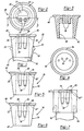
- Figure 1 is a side view of a closure assembly in accordance with the present invention;
- Figure 2 is a top view of a closure assembly in accordance with the present invention;
- Figure 3 is a cross-sectional view of Figure 2 taken along line 3-3;
- Figure 4 is a top view of a preferred embodiment of the present invention;
- Figure 5 is a side view of a preferred embodiment of the present invention;
- Figure 6 is a side view of a preferred embodiment of the present invention; and
- Figure 7 is a side view of another embodiment of the present invention.
-
- Referring to the Figures, a closure assembly for sealing a microorganism container is generally shown and designated by the
reference numeral 20. Referring specifically to Figure 1, theclosure assembly 20 includes a resilient seal orplug 24 for sealing theclosure 20 to acontainer 50. Theclosure assembly 20 further includesfilter membrane 28 integrally disposed within the seal orplug 24 for allowing sterile gas exchange therethrough. - The
container 50 can be a flask or other known type of container which retains liquids and microorganisms therein for the purpose of propagating aerobic or anaerobic microorganisms. Thecontainer 50 is preferably made of glass or pyrex® or other suitable materials which can withstand autoclaving or other such methods of sterilisation. - The
closure 20 includes a port orpassageway 26 axially disposed within the seal orplug 24 which extends through the seal orplug 24 allowing fluid communication between thecontainer 50 and the external atmosphere. The passageway orport 26 is defined by acylindrical side wall 25. - In one embodiment, the seal or
plug 24 is generally frustoconical in cross-section. That is, the seal orplug 24 can be tapered and have a shape similar to a wedge. When an insertion end 42 of the seal orplug 24 is inserted into thecontainer 50, theclosure assembly 20 forms an air and liquid-tight seal with aninner surface 52 of thecontainer 50. That is, theside wall 25 of the seal orplug 24 is graduated and, therefore, it can be inserted intocontainers 50 having variously sized openings therein and form an air and liquid-tight seal therewith. The cross-sectional diameter of thewall 25 of the seal orplug 24 increases in the direction opposite of theinsertion end 42 of the seal orplug 24 as shown in Figures 1 and 4. Since an infinite number of diameters can be accommodated, theclosure assembly 20 can be used with and create both air and liquid-tight seals with variously sizedcontainers 50. - Referring to Figure 7, another embodiment of the
closure assembly 20 is shown. In this embodiment, theclosure 20 has a generally cylindrical shape and is designed to fit over thecontainer 50 and forms an air and liquid tight seal with anouter surface 54 of thecontainer 50. The embodiment shown in Figure 7 can be made in any desired size and thereby can be constructed to fit anysize container 50. - The resilient seal or
plug 24 is a generally unitary member formed of a resilient material which is capable of conforming and sealing to the contours of the openings of flasks orcontainers 50. That is, the resilient seal orplug 24 is constructed of a material which is capable of deflecting and/or yielding to sealingly conform to or to sealingly engage with theinner surface 52 of a container such that both an air- and liquid-tight seal is formed and maintained therewith. The seal orplug 24 can be constructed or manufactured from suitable flexible and resilient materials, for example, silicones, natural or synthetic rubber materials, polyolefins, polyamides, co-polymers, and fluoroplastics. This list is not meant to be exhaustive and can include other suitable materials known to those skilled in the art. - The
closure assembly 20 further includes afilter membrane 28 in the form of a filter having atop surface 29, abottom surface 30, and aperipheral edge 31 which extends across the port orpassageway 26. In a preferred embodiment, thefilter membrane 28 is somewhat flat or disk-shaped. Theperipheral edge 31 of thefilter membrane 28 is sealed within the port orpassageway 26 which axially extends through the seal orplug 24. The seal between theperipheral edge 31 and the seal orplug 24 must be both air- and liquid-tight in order to maintain the integrity and/or sterility of theclosure 20 and contents of thecontainer 50. Thefilter membrane 28 must be positioned and affixed within the port orpassageway 26 such that any fluids (gaseous or liquid) can only pass through thefilter membrane 28 and not around the periphery of thefilter media 28 thereby breaching the sterility of theclosure 20/container 50 system. In other words, theperipheral edge 31 of thefilter membrane 28 must be affixed to the plug or seal 24 in such a manner to form a seal therein such that when theclosure 20 is in place in the opening of thecontainer 50, fluid and/or gas exchange can only occur across thefilter media 28 thereby maintaining the sterility of thecontainer 50 and its contents. - The
filter membrane 28 can be sealed within thepassageway 26 of the seal orplug 24 by affixing or integrally moulding thefilter 28 within the port orpassageway 26. - Referring to Figures 1, 5, 6, and 7, there is shown additional embodiments of the present invention. The embodiments illustrated in Figures 1, 5, 6, and 7 are similar in certain respects, accordingly, like elements have been designated with like prime numerals.
- In order to provide rigidity in support to the
filter membrane 28, asupport 32, 32', 32'', 32''' can be provided adjacent to thefilter 28. - Referring specifically to Figure 1, the support can be disposed about and below the
peripheral edge 31 of thefilter membrane 28. Referring specifically to Figure 5, the support 32' can be disposed about theperipheral edge 31 at a position approximately level with the position of theperipheral edge 31. Referring specifically to Figure 6, the support 32'' can be disposed about and above theperipheral edge 31 of thefilter membrane 28. In all of the embodiments shown in Figures 1, 5, 6, and 7, thesupport 32, 32', 32'', 32''' can be a ring moulded or affixed to either the bottom of theperipheral edge 31, the top of theperipheral edge 31, or moulded or affixed to theperipheral edge 31 in the same plane as thefilter membrane 28 or moulded or affixed to both the top and bottom of theperipheral edge 31. The support can be constructed of any suitable materials including a metal, such as stainless steel, and plastic. The material comprising thesupport 32 must be able to withstand the temperatures and pressures encountered during autoclaving. - Alternatively, the
support 32, 32', 32'',32''' can include a mesh-like matrix disposed on either the top 29, bottom 30, or both top 29 and bottom 30 of the filter membrane 28 (not shown). Thesupport member 32, 32', 32'', 32''' can be constructed of any suitable material, such as the same material as comprises theclosure 20. - The
filter membrane 28 and thesupport 32, 32', 32'', 32''' are positioned within the port orpassageway 26 of the seal or plug 24 and can be fixed in place by means such as affixation during moulding of the seal or plug 24 or can be positioned and fixed in place following moulding of the seal or plug 24 such as by gluing or embedding thefilter 28 andsupport 32, 32', 32'', 32''' in the plug or seal 24 to theseal closure 20. - The
filter membrane 28 and thesupport 32, 32', 32'', 32''' can be affixed to one another by means including moulding or other types of affixation such as gluing or cementing. - The
filter membrane 28 can be made of any suitable material such as depth media including HEPA or ULPA rated glass microfibre, hydrophobic membranes such as polypropylenes, polytetrafluoroethylenes (PTFE), and polysulfones. This list of materials is not intended to be exhaustive and other suitable materials known to these skilled in the art can be utilised. Thefilter membrane 28 is made from a material which is capable of permitting the exchange of gas thereacross, but will not permit the passage of micro-organic contaminants. - Referring specifically to Figure 3, the
closure assembly 20 can include at least one aperture oropening 36 extending therethrough to allow for the insertion of tubing, thermometer or the like therein. Since theaperture 36 is disposed within the seal or plug 24, theaperture 36 is able to conform and perfect a seal about any tubing or the like placed therein. Theaperture 36 allows for sterile access to the interior of thecontainer 50 and the contents therein without the risk of introducing any contamination. - The present invention further provides a method of making a
flask closure 20 by moulding the seal or plug 24 having the port orpassageway 26 extending therethrough and sealing theperipheral edge 31 of thefilter membrane 28 within the port orpassageway 26. That is, a one-piece,unitary closure assembly 20 is formed while simultaneously sealing theperipheral edge 31 of thefilter 28 within thepassageway 26 in the seal or plug 24. The moulding step is accomplished by techniques well known to these skilled in the art. - The present invention can be practiced with various
shape filter membranes 28 as shown in Figure 1 and Figure 4 as long as thefilter membrane 28 can be supported and theperipheral edge 31 of thefilter membrane 28 is available for sealing affixation to thepassageway 26 of thesealer plug 24. - The method of forming the
closure assembly 20 can also include the step of disposing thesupport 32, 32', 32'',32''' within thepassageway 26 either during the moulding step or following the moulding step. The method generally includes sizing thefilter media 28 to a desired size. The supports 32,32',32'',32''' can also be specifically dimensioned. Thefilter membrane 28 and thesupports 32,32',32'',32''' can be loaded into a mould cavity and are held in place on top of core pins by locator pins. A suitable material, such as silicone, can then be injected into the mould cavity. The silicone fills the mould cavity and encapsulates thefilter membrane 28 and supports 32,32',32'',32''' and can then be cured by means such as utilising heat from the mould. After a suitable curing period, theclosure assembly 20 can be removed from the mould.
Claims (6)
- A closure (20) for sealing a micro-organism container (50), said closure (20) comprising:characterised in that said sealing means is a resilient plug member (24) of a resilient material capable of conforming to said container (50) such that an air-tight and liquid-tight seal is formed therewith, said resilient plug member (24) being a unitary member having said passageway extending therethrough, and said peripheral edge (31) of said filter membrane (28) is sealed within said passageway (26) to an internal wall of said plug member (24), said seal between said peripheral edge (31) and said internal wall of said plug member being air-tight and liquid-tight to allow for sterile gas exchange through said passageway (26) of said plug member.i) sealing means for sealing the container (50);ii) a passageway (26) extending through said sealing means, which passageway (26) allows fluid communication between said container (50) and the external atmosphere; andiii) a filter membrane (28) extending across said passageway (26), said filter membrane (28) having a top surface (29), a bottom surface (30) and a peripheral edge (31);
- A closure (20) according to claim 1, wherein said filter membrane (28) is of a hydrophobic material.
- A closure (20) according to any preceding claim, wherein said filter membrane (28) includes at least one support means (32, 32', 32", 32''') disposed adjacent to said filter membrane (28) for supporting said filter membrane (28).
- A closure (20) according to any preceding claim, wherein said resilient plug member (24) includes at least one aperture (36) extending therethrough to allow insertion of tubing therein.
- A closure (20) according to any preceding claim, wherein said resilient plug member (24) has a frustoconical cross-section.
- A method of producing a closure according to any of claims 1 to 6, which method comprises the steps of:a) forming said resilient plug member having a passageway extending therethrough by moulding; andb) sealing said peripheral edge of said filter membrane within said passageway either during or after step (a).
Applications Claiming Priority (2)
| Application Number | Priority Date | Filing Date | Title |
|---|---|---|---|
| US08/606,596 US6170684B1 (en) | 1996-02-26 | 1996-02-26 | Flask vent and method of making same |
| US606596 | 1996-02-26 |
Publications (3)
| Publication Number | Publication Date |
|---|---|
| EP0791649A2 EP0791649A2 (en) | 1997-08-27 |
| EP0791649A3 EP0791649A3 (en) | 1998-05-20 |
| EP0791649B1 true EP0791649B1 (en) | 2002-07-17 |
Family
ID=24428623
Family Applications (1)
| Application Number | Title | Priority Date | Filing Date |
|---|---|---|---|
| EP97200350A Expired - Lifetime EP0791649B1 (en) | 1996-02-26 | 1997-02-10 | Flask vent and method of making same |
Country Status (3)
| Country | Link |
|---|---|
| US (1) | US6170684B1 (en) |
| EP (1) | EP0791649B1 (en) |
| DE (1) | DE69713924T2 (en) |
Families Citing this family (14)
| Publication number | Priority date | Publication date | Assignee | Title |
|---|---|---|---|---|
| US6193088B1 (en) * | 1996-02-26 | 2001-02-27 | Monty E. Vincent | Flask vent and method of making same |
| JP3333813B2 (en) * | 1996-11-20 | 2002-10-15 | トヨタ自動車株式会社 | Startup control device for occupant protection device |
| USD443511S1 (en) | 1999-11-19 | 2001-06-12 | Matz Rubber Co., Inc. | Fermentation bung |
| US6619499B1 (en) * | 2000-09-06 | 2003-09-16 | Peter Lin | Vented lid assembly for a sanitary container |
| US20040048392A1 (en) * | 2002-09-09 | 2004-03-11 | The Gov't Of The U.S.A As Represented By The Secretary Of The Dept.Of Health And Human Services | Container for drying biological samples, method of making such container, and method of using same |
| US7357709B2 (en) * | 2004-04-12 | 2008-04-15 | Gore Enterprise Holdings | Metal vent |
| US20070028416A1 (en) * | 2005-08-04 | 2007-02-08 | Dunkel James W | Sucket bucket |
| WO2007071287A1 (en) * | 2005-12-22 | 2007-06-28 | Pentacore International Holding Bv | Laboratory cultutre flask with snap-on cap |
| EP2382141B1 (en) * | 2008-12-31 | 2014-11-19 | W.L. Gore & Associates GmbH | Venting device |
| US20100237013A1 (en) * | 2009-02-13 | 2010-09-23 | Millipore Corporation | Autonomous filter element |
| WO2011056230A1 (en) * | 2009-11-05 | 2011-05-12 | Mcadams Todd A | Self-contained breathing closure and container |
| US9010321B2 (en) * | 2011-12-16 | 2015-04-21 | 12th Man Technologies, Inc. | Bacteria filter and heating system |
| EP2875867B1 (en) | 2013-11-26 | 2016-06-01 | Eppendorf Ag | Culture vessel/vessel with screw-on lid |
| EP3261761B1 (en) | 2015-02-27 | 2022-04-13 | Corning Incorporated | Fitted lid for multi-well plate |
Family Cites Families (21)
| Publication number | Priority date | Publication date | Assignee | Title |
|---|---|---|---|---|
| US2153981A (en) | 1936-04-03 | 1939-04-11 | Winthrop Chem Co Inc | Medicinal container |
| US2191447A (en) * | 1937-04-21 | 1940-02-27 | Emery S Beardsley | Container closure |
| US2186908A (en) * | 1939-02-01 | 1940-01-09 | Burroughs Wellcome Co | Air filtering stopper |
| US3019932A (en) | 1958-12-12 | 1962-02-06 | Frank K Singiser | Universal cap |
| US3313712A (en) | 1963-03-25 | 1967-04-11 | Marilyn E George | Apparatus for the detection of living microbial contaminants in petroleum products |
| US3326401A (en) | 1965-10-11 | 1967-06-20 | Bellco Glass Inc | Closure |
| US4136796A (en) | 1974-04-11 | 1979-01-30 | Greif Bros. Corporation | Vented closure |
| US3952902A (en) | 1974-04-26 | 1976-04-27 | Cutter Laboratories, Inc. | Closure cap for plasma receiving assembly |
| CH582541A5 (en) | 1974-09-10 | 1976-12-15 | Infors Ag | Biological cultures vibrating system - in Erlenmeyer flasks with sterile filter in stopper and two independent air lines |
| JPS54104986A (en) * | 1978-01-23 | 1979-08-17 | American Hospital Supply Corp | Closing member for pasteurized liquid container |
| FR2429431A1 (en) | 1978-06-22 | 1980-01-18 | Eurand France | METHOD AND APPARATUS FOR MONITORING THE ACTIVITY AND TITLE OF MEDICAMENTS PRESENTED IN GALENIC FORMS WITH PROGRESSIVE RELEASE OF THE MEDICINAL PRODUCT |
| US4235344A (en) | 1979-01-29 | 1980-11-25 | Baxter Travenol Laboratories, Inc. | Irrigation cap |
| US4271973A (en) * | 1979-03-19 | 1981-06-09 | United States Of America | Sterility testing vessel |
| EP0264464B1 (en) | 1985-10-19 | 1992-05-13 | Daikin Industries, Limited | Culture vessel |
| DE3628930A1 (en) | 1986-08-26 | 1988-05-05 | Greiner & Soehne C A | CONTAMINATION-SAFE CAP, IN PARTICULAR SCREW CAP FOR CELL CULTURE BOTTLES |
| US4935371A (en) * | 1986-12-31 | 1990-06-19 | American Sterilizer Company | Sterilizable gas permeable container for use in culturing living cells |
| US5188628A (en) * | 1990-11-06 | 1993-02-23 | Sandoz Ltd. | Closure device for enteral fluid containers |
| US5180073A (en) * | 1991-05-17 | 1993-01-19 | Biomedical Polymers, Inc. | Permeable cap for flask |
| US5395006A (en) | 1993-04-29 | 1995-03-07 | Verma; Kuldeep | Fermentation vessels and closures therefor |
| US5358872A (en) | 1993-08-12 | 1994-10-25 | Becton, Dickinson And Company | Vessel and closure assembly |
| US5522769A (en) | 1994-11-17 | 1996-06-04 | W. L. Gore & Associates, Inc. | Gas-permeable, liquid-impermeable vent cover |
-
1996
- 1996-02-26 US US08/606,596 patent/US6170684B1/en not_active Expired - Lifetime
-
1997
- 1997-02-10 DE DE69713924T patent/DE69713924T2/en not_active Expired - Fee Related
- 1997-02-10 EP EP97200350A patent/EP0791649B1/en not_active Expired - Lifetime
Also Published As
| Publication number | Publication date |
|---|---|
| US6170684B1 (en) | 2001-01-09 |
| EP0791649A2 (en) | 1997-08-27 |
| EP0791649A3 (en) | 1998-05-20 |
| DE69713924D1 (en) | 2002-08-22 |
| DE69713924T2 (en) | 2003-03-27 |
Similar Documents
| Publication | Publication Date | Title |
|---|---|---|
| US6193088B1 (en) | Flask vent and method of making same | |
| US6170684B1 (en) | Flask vent and method of making same | |
| CN1329501C (en) | Culture dish and bioreactor system | |
| FI61515B (en) | ANORDING FOR MICRO-ORGANISMS | |
| DE69806527T2 (en) | Growth device and method for its application | |
| US4993573A (en) | Bottle closure | |
| EP2085463B1 (en) | Culture plate comprising a lid for lateral ventilation | |
| JPH08173146A (en) | Closure assembly for cell culture vessels | |
| US4215198A (en) | Sterility testing unit | |
| JPH01503595A (en) | Contamination prevention closures, especially screw closures for cell culture bottles | |
| EP2776550A2 (en) | Cassette for sterility testing | |
| CN105828842B (en) | Sample Preparation Units and Sample Preparation Devices | |
| JPH07163333A (en) | Assembly of container and closing member | |
| US20040063169A1 (en) | Filtration assembly | |
| EP0337677A2 (en) | Vent cap | |
| EP1069181A2 (en) | Closure assembly for multiwell vessel | |
| CA3172354A1 (en) | Cell culture container | |
| US4812408A (en) | Blood culture system | |
| EP1383861B1 (en) | Filtration assembly | |
| AU718368B2 (en) | Resuable vented flask cap cover | |
| JPH01262789A (en) | Culture bottle and valve assembly | |
| CN108148759A (en) | A kind of multipurpose gas-permeable container for attached cell culture/co-cultivation | |
| FI91165B (en) | Bottle-growing equipment | |
| US20240368514A1 (en) | Sbs-format single, or dual, deep well stackable cell culture disposable well plate and closure | |
| JPH0539300U (en) | Plant culture vessel |
Legal Events
| Date | Code | Title | Description |
|---|---|---|---|
| PUAI | Public reference made under article 153(3) epc to a published international application that has entered the european phase |
Free format text: ORIGINAL CODE: 0009012 |
|
| AK | Designated contracting states |
Kind code of ref document: A2 Designated state(s): DE FR GB |
|
| PUAL | Search report despatched |
Free format text: ORIGINAL CODE: 0009013 |
|
| AK | Designated contracting states |
Kind code of ref document: A3 Designated state(s): DE FR GB |
|
| 17P | Request for examination filed |
Effective date: 19981109 |
|
| 17Q | First examination report despatched |
Effective date: 20000627 |
|
| RAP1 | Party data changed (applicant data changed or rights of an application transferred) |
Owner name: WHATMAN, INC. |
|
| GRAG | Despatch of communication of intention to grant |
Free format text: ORIGINAL CODE: EPIDOS AGRA |
|
| GRAG | Despatch of communication of intention to grant |
Free format text: ORIGINAL CODE: EPIDOS AGRA |
|
| GRAH | Despatch of communication of intention to grant a patent |
Free format text: ORIGINAL CODE: EPIDOS IGRA |
|
| GRAH | Despatch of communication of intention to grant a patent |
Free format text: ORIGINAL CODE: EPIDOS IGRA |
|
| GRAA | (expected) grant |
Free format text: ORIGINAL CODE: 0009210 |
|
| AK | Designated contracting states |
Kind code of ref document: B1 Designated state(s): DE FR GB |
|
| REG | Reference to a national code |
Ref country code: GB Ref legal event code: FG4D |
|
| REF | Corresponds to: |
Ref document number: 69713924 Country of ref document: DE Date of ref document: 20020822 |
|
| ET | Fr: translation filed | ||
| PLBE | No opposition filed within time limit |
Free format text: ORIGINAL CODE: 0009261 |
|
| STAA | Information on the status of an ep patent application or granted ep patent |
Free format text: STATUS: NO OPPOSITION FILED WITHIN TIME LIMIT |
|
| 26N | No opposition filed |
Effective date: 20030422 |
|
| PGFP | Annual fee paid to national office [announced via postgrant information from national office to epo] |
Ref country code: DE Payment date: 20050203 Year of fee payment: 9 |
|
| PGFP | Annual fee paid to national office [announced via postgrant information from national office to epo] |
Ref country code: FR Payment date: 20050208 Year of fee payment: 9 |
|
| PGFP | Annual fee paid to national office [announced via postgrant information from national office to epo] |
Ref country code: GB Payment date: 20050209 Year of fee payment: 9 |
|
| PG25 | Lapsed in a contracting state [announced via postgrant information from national office to epo] |
Ref country code: GB Free format text: LAPSE BECAUSE OF NON-PAYMENT OF DUE FEES Effective date: 20060210 |
|
| PG25 | Lapsed in a contracting state [announced via postgrant information from national office to epo] |
Ref country code: DE Free format text: LAPSE BECAUSE OF NON-PAYMENT OF DUE FEES Effective date: 20060901 |
|
| GBPC | Gb: european patent ceased through non-payment of renewal fee |
Effective date: 20060210 |
|
| REG | Reference to a national code |
Ref country code: FR Ref legal event code: ST Effective date: 20061031 |
|
| PG25 | Lapsed in a contracting state [announced via postgrant information from national office to epo] |
Ref country code: FR Free format text: LAPSE BECAUSE OF NON-PAYMENT OF DUE FEES Effective date: 20060228 |