EP0791541A2 - Drinking can - Google Patents
Drinking can Download PDFInfo
- Publication number
- EP0791541A2 EP0791541A2 EP97870014A EP97870014A EP0791541A2 EP 0791541 A2 EP0791541 A2 EP 0791541A2 EP 97870014 A EP97870014 A EP 97870014A EP 97870014 A EP97870014 A EP 97870014A EP 0791541 A2 EP0791541 A2 EP 0791541A2
- Authority
- EP
- European Patent Office
- Prior art keywords
- mouth piece
- drinking
- lip
- tear
- end wall
- Prior art date
- Legal status (The legal status is an assumption and is not a legal conclusion. Google has not performed a legal analysis and makes no representation as to the accuracy of the status listed.)
- Withdrawn
Links
Images
Classifications
-
- B—PERFORMING OPERATIONS; TRANSPORTING
- B65—CONVEYING; PACKING; STORING; HANDLING THIN OR FILAMENTARY MATERIAL
- B65D—CONTAINERS FOR STORAGE OR TRANSPORT OF ARTICLES OR MATERIALS, e.g. BAGS, BARRELS, BOTTLES, BOXES, CANS, CARTONS, CRATES, DRUMS, JARS, TANKS, HOPPERS, FORWARDING CONTAINERS; ACCESSORIES, CLOSURES, OR FITTINGS THEREFOR; PACKAGING ELEMENTS; PACKAGES
- B65D25/00—Details of other kinds or types of rigid or semi-rigid containers
- B65D25/38—Devices for discharging contents
- B65D25/40—Nozzles or spouts
-
- B—PERFORMING OPERATIONS; TRANSPORTING
- B65—CONVEYING; PACKING; STORING; HANDLING THIN OR FILAMENTARY MATERIAL
- B65D—CONTAINERS FOR STORAGE OR TRANSPORT OF ARTICLES OR MATERIALS, e.g. BAGS, BARRELS, BOTTLES, BOXES, CANS, CARTONS, CRATES, DRUMS, JARS, TANKS, HOPPERS, FORWARDING CONTAINERS; ACCESSORIES, CLOSURES, OR FITTINGS THEREFOR; PACKAGING ELEMENTS; PACKAGES
- B65D17/00—Rigid or semi-rigid containers specially constructed to be opened by cutting or piercing, or by tearing of frangible members or portions
- B65D17/28—Rigid or semi-rigid containers specially constructed to be opened by cutting or piercing, or by tearing of frangible members or portions at lines or points of weakness
- B65D17/401—Rigid or semi-rigid containers specially constructed to be opened by cutting or piercing, or by tearing of frangible members or portions at lines or points of weakness characterised by having the line of weakness provided in an end wall
- B65D17/4012—Rigid or semi-rigid containers specially constructed to be opened by cutting or piercing, or by tearing of frangible members or portions at lines or points of weakness characterised by having the line of weakness provided in an end wall for opening partially by means of a tearing tab
-
- B—PERFORMING OPERATIONS; TRANSPORTING
- B65—CONVEYING; PACKING; STORING; HANDLING THIN OR FILAMENTARY MATERIAL
- B65D—CONTAINERS FOR STORAGE OR TRANSPORT OF ARTICLES OR MATERIALS, e.g. BAGS, BARRELS, BOTTLES, BOXES, CANS, CARTONS, CRATES, DRUMS, JARS, TANKS, HOPPERS, FORWARDING CONTAINERS; ACCESSORIES, CLOSURES, OR FITTINGS THEREFOR; PACKAGING ELEMENTS; PACKAGES
- B65D2517/00—Containers specially constructed to be opened by cutting, piercing or tearing of wall portions, e.g. preserving cans or tins
- B65D2517/0001—Details
- B65D2517/001—Action for opening container
- B65D2517/0013—Action for opening container pull-out tear panel, e.g. by means of a tear-tab
-
- B—PERFORMING OPERATIONS; TRANSPORTING
- B65—CONVEYING; PACKING; STORING; HANDLING THIN OR FILAMENTARY MATERIAL
- B65D—CONTAINERS FOR STORAGE OR TRANSPORT OF ARTICLES OR MATERIALS, e.g. BAGS, BARRELS, BOTTLES, BOXES, CANS, CARTONS, CRATES, DRUMS, JARS, TANKS, HOPPERS, FORWARDING CONTAINERS; ACCESSORIES, CLOSURES, OR FITTINGS THEREFOR; PACKAGING ELEMENTS; PACKAGES
- B65D2517/00—Containers specially constructed to be opened by cutting, piercing or tearing of wall portions, e.g. preserving cans or tins
- B65D2517/0001—Details
- B65D2517/0047—Provided with additional elements other than for closing the opening
- B65D2517/0049—Straws, spouts, funnels, or other devices facilitating pouring or emptying
-
- B—PERFORMING OPERATIONS; TRANSPORTING
- B65—CONVEYING; PACKING; STORING; HANDLING THIN OR FILAMENTARY MATERIAL
- B65D—CONTAINERS FOR STORAGE OR TRANSPORT OF ARTICLES OR MATERIALS, e.g. BAGS, BARRELS, BOTTLES, BOXES, CANS, CARTONS, CRATES, DRUMS, JARS, TANKS, HOPPERS, FORWARDING CONTAINERS; ACCESSORIES, CLOSURES, OR FITTINGS THEREFOR; PACKAGING ELEMENTS; PACKAGES
- B65D2517/00—Containers specially constructed to be opened by cutting, piercing or tearing of wall portions, e.g. preserving cans or tins
- B65D2517/0001—Details
- B65D2517/0058—Other details of container end panel
- B65D2517/0059—General cross-sectional shape of container end panel
- B65D2517/0061—U-shaped
- B65D2517/0062—U-shaped and provided with an additional U-shaped peripheral channel
Definitions
- the present invention relates to a drinking can comprising two flat or substantially flat end walls, one of which is provided with a tear-off lip connected to a ring for tearing off this lip.
- An object of the invention is now to propose an original solution for the problems set forth hereinabove.
- a cylindrical mouth piece is fixed, on the inner side of the drinking can, onto said tear-off lip, the connection between this mouth piece and the tear-off lip is provided laterally of the mouth piece in such a manner that when tearing off the tear-off lip, the mouth piece projects through the opening formed thereby in the end wall, and the mouth piece shows a base portion provided with hook shaped projections designed to receive the edge of said opening so as to ensure a liquid tight seal between mouth piece and the respective end wall.
- a grid is provided within said mouth piece.
- said mouth piece is made at least partially according to the accordion principle.
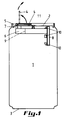
- Figure is a longitudinal section, which has been kept schematically, through a drinking can according to the invention prior to opening thereof.
- Figure 2 is a top plan view on the drinking can according to Figure 1.
- Figure 3 is a longitudinal section, which has been kept schematically, through a drinking can according to the invention after having opened it.
- Figure 4 is a top plan view on the drinking can according to Figure 3.
- the drinking can shown in these figures is of the standard type comprising a cylindrical body 1 and two substantially flat end faces 2 and 3.
- 2 is the upper and 3 the lower end wall.
- a cylindrical mouth piece 6 is now connected to this tear-off lip 5.
- the connection between the cylindrical mouth piece 6 and the tear-off lip 5 has been indicated with reference 7.
- a base portion 8 To the bottom of the cylindrical mouth piece 6 (seen in the use position) is connected a base portion 8, the circumference of which is somewhat larger than the circumference of the opening achieved upon tearing off the tear-off lip.
- circumference is meant the profile of the base portion considered in top plan view as shown in Figure 4.
- a grid 9 is applied which makes intrusion of insects entirely impossible.
- the base portion 8 is provided with four hook shaped projections 10 which snap over the edge of the opening formed by tearing off the tear-off lip 5, when pulling the cylindrical mouth piece 6 upwards. In this way, a satisfying connection is achieved between the base portion and the end wall 2 of the drinking can.
- the small stopper 11 In order to be able to drink, the small stopper 11 has to be removed from the end wall 2. This can be done very easily since the connection between this small stopper and the thin metallic end wall 2 is technically well feasible.
- the small stopper 11 may be stuck for example in a temporary sealing membrane connected to the metallic end wall.
- a possible variant embodiment of the here-described mouth piece consists in making this piece in the form of an accordion. This enables to compress the cylindrical mouth piece.
- the drinking can according to the invention provides an original solution for the problems as they have been set forth in the preamble.
Abstract
Description
- The present invention relates to a drinking can comprising two flat or substantially flat end walls, one of which is provided with a tear-off lip connected to a ring for tearing off this lip.
- Although the production and the use of these drinking cans continuous to show an upward trend and said cans remained substantially unchanged for years, it is not clear why no evolution can be noticed in the concept of this product.
- It is indeed generally known that the cans which are nowadays generally in circulation are not satisfying in case one or more of the following aspects of the drinking cans are taken into consideration:
- 1. Hygiene and lack of comfort when drinking;
- 2. Insects penetrating into the cans;
- 3. Injuries due to the sharp edges of the tear-off lip and the like;
- 4. Difficult to handle by persons with back or neck vertebra troubles;
- 5. Proliferation of bacteria in the circumferential edge of the respective end wall of the drinking can.
- An explication of this unchanged situation has to be sought in the difficulty of combining technically reliable with economically feasible solutions.
- An object of the invention is now to propose an original solution for the problems set forth hereinabove.
- In order to enable this in accordance with the invention, a cylindrical mouth piece is fixed, on the inner side of the drinking can, onto said tear-off lip, the connection between this mouth piece and the tear-off lip is provided laterally of the mouth piece in such a manner that when tearing off the tear-off lip, the mouth piece projects through the opening formed thereby in the end wall, and the mouth piece shows a base portion provided with hook shaped projections designed to receive the edge of said opening so as to ensure a liquid tight seal between mouth piece and the respective end wall.
- In an advantageous embodiment, a grid is provided within said mouth piece.
- In a possible embodiment, said mouth piece is made at least partially according to the accordion principle.
- Other details and advantages of the invention will become apparent from the following description of the drinking can according to the invention. This description is only given by way of example and does not restrict the invention. The reference numerals relate to the figures annexed hereto.
- Figure is a longitudinal section, which has been kept schematically, through a drinking can according to the invention prior to opening thereof.
- Figure 2 is a top plan view on the drinking can according to Figure 1.
- Figure 3 is a longitudinal section, which has been kept schematically, through a drinking can according to the invention after having opened it.
- Figure 4 is a top plan view on the drinking can according to Figure 3.
- The drinking can shown in these figures is of the standard type comprising a
cylindrical body 1 and two substantiallyflat end faces - By pulling the ring 4 fixed to the
upper end wall 2 upwards, an opening is pulled out of thiswall 2. The movement performed by this ring is shown in Figure 1 by means of an arrow (in full line). The position of the pulled up ring is shown in mixed line. - Pulling the ring 4 further upwards produces an opening in the
upper end wall 2 which corresponds to the tear-off lip 5 in this wall. The shape of this opening can be seen clearly in Figure 4. - According to the invention, a
cylindrical mouth piece 6 is now connected to this tear-off lip 5. The connection between thecylindrical mouth piece 6 and the tear-off lip 5 has been indicated with reference 7. - To the bottom of the cylindrical mouth piece 6 (seen in the use position) is connected a
base portion 8, the circumference of which is somewhat larger than the circumference of the opening achieved upon tearing off the tear-off lip. By circumference is meant the profile of the base portion considered in top plan view as shown in Figure 4. - Within the cylindrical mouth piece, a
grid 9 is applied which makes intrusion of insects entirely impossible. - The
base portion 8 is provided with four hookshaped projections 10 which snap over the edge of the opening formed by tearing off the tear-off lip 5, when pulling thecylindrical mouth piece 6 upwards. In this way, a satisfying connection is achieved between the base portion and theend wall 2 of the drinking can. - In order to be able to drink, the
small stopper 11 has to be removed from theend wall 2. This can be done very easily since the connection between this small stopper and the thinmetallic end wall 2 is technically well feasible. Thesmall stopper 11 may be stuck for example in a temporary sealing membrane connected to the metallic end wall. - A possible variant embodiment of the here-described mouth piece consists in making this piece in the form of an accordion. This enables to compress the cylindrical mouth piece.
- Hence, the drinking can according to the invention provides an original solution for the problems as they have been set forth in the preamble.
- The invention is not limited to the here-described embodiment and modifications to this embodiment remain covered by this application in as far as they fall within the scope of the claims annexed hereto.
Claims (5)
- A drinking can comprising two flat or substantially flat end walls, one of which is provided with a tear-off lip connected to a ring for tearing off this lip, characterized in that on the inner side of the drinking can, a cylindrical mouth piece (6) is fixed onto said tear-off lip (5), in that the connection (7) between this mouth piece (6) and the tear-off lip (5) is provided laterally of the mouth piece in such a manner that when tearing off the tear-off lip (5), the mouth piece (6) projects through the opening formed thereby in the end wall, and in that the mouth piece (6) shows a base portion (8) provided with hook shaped projections (10) designed to receive the edge of said opening so as to ensure a liquid tight seal between mouth piece (6) and the respective end wall (2).
- A drinking can according to claim 1, characterized in that said mouth piece (6) consists of a flexible material.
- A drinking can according to either one of the claims 1 and 2, characterized in that a grid (9) is provided within said mouth piece (6).
- A drinking can according to any one of the claims 1 to 3, characterized in that said mouth piece (6) is at least partially made according to the accordion principle.
- A drinking can according to any one of the claims 1 to 4, characterized in that said flat end wall comprising the tear-off lip (5) is further provided with an air inlet formed upon lifting a button (11) which is part of a temporary sealing membrane.
Applications Claiming Priority (2)
| Application Number | Priority Date | Filing Date | Title |
|---|---|---|---|
| BE9600155A BE1009952A6 (en) | 1996-02-22 | 1996-02-22 | Drink can. |
| BE9600155 | 1996-02-22 |
Publications (2)
| Publication Number | Publication Date |
|---|---|
| EP0791541A2 true EP0791541A2 (en) | 1997-08-27 |
| EP0791541A3 EP0791541A3 (en) | 1998-03-25 |
Family
ID=3889560
Family Applications (1)
| Application Number | Title | Priority Date | Filing Date |
|---|---|---|---|
| EP97870014A Withdrawn EP0791541A3 (en) | 1996-02-22 | 1997-02-07 | Drinking can |
Country Status (2)
| Country | Link |
|---|---|
| EP (1) | EP0791541A3 (en) |
| BE (1) | BE1009952A6 (en) |
Citations (4)
| Publication number | Priority date | Publication date | Assignee | Title |
|---|---|---|---|---|
| US3946895A (en) * | 1974-05-30 | 1976-03-30 | Pugh William A | Container lid with tear-out closure and straw |
| US4537324A (en) * | 1984-11-06 | 1985-08-27 | Wang Ming Sheng | Automatic straw-emerging device for easy-to-open beverage can of press-down type sealing tap |
| US4792083A (en) * | 1987-11-30 | 1988-12-20 | Zion Yassur | Drinking tubes and covers for beverage containers and beverage containers incorporating the same |
| US5172827A (en) * | 1992-05-20 | 1992-12-22 | Chang In Y | Beverage container |
-
1996
- 1996-02-22 BE BE9600155A patent/BE1009952A6/en not_active IP Right Cessation
-
1997
- 1997-02-07 EP EP97870014A patent/EP0791541A3/en not_active Withdrawn
Patent Citations (4)
| Publication number | Priority date | Publication date | Assignee | Title |
|---|---|---|---|---|
| US3946895A (en) * | 1974-05-30 | 1976-03-30 | Pugh William A | Container lid with tear-out closure and straw |
| US4537324A (en) * | 1984-11-06 | 1985-08-27 | Wang Ming Sheng | Automatic straw-emerging device for easy-to-open beverage can of press-down type sealing tap |
| US4792083A (en) * | 1987-11-30 | 1988-12-20 | Zion Yassur | Drinking tubes and covers for beverage containers and beverage containers incorporating the same |
| US5172827A (en) * | 1992-05-20 | 1992-12-22 | Chang In Y | Beverage container |
Also Published As
| Publication number | Publication date |
|---|---|
| EP0791541A3 (en) | 1998-03-25 |
| BE1009952A6 (en) | 1997-11-04 |
Similar Documents
| Publication | Publication Date | Title |
|---|---|---|
| US5119955A (en) | Sanitary can closure | |
| US6450358B1 (en) | Hygienic beverage can attachment | |
| US3952914A (en) | Re-sealable container lid | |
| EP0427688A1 (en) | Screw top closure | |
| EP0798226A3 (en) | Two-piece plastic container and removable cover | |
| US4252247A (en) | Tear-open can lid with push-in tabs | |
| ZA959238B (en) | Plastic snap closure with anti-tamper strip and method of its manufacture | |
| US5292022A (en) | Closure for beverages metal containers | |
| EP1798153A3 (en) | Packaging container and method of manufacturing the same | |
| US20080073365A1 (en) | Reclosable Foil Lid | |
| EP0791541A2 (en) | Drinking can | |
| CA2021036C (en) | Packing container | |
| MY105276A (en) | Natural latex ltd. | |
| EP1948524A1 (en) | Drinks can with a drinking attachment | |
| EP0999143A3 (en) | Triangular composite container | |
| EP0444385A1 (en) | A container for drinks having a drinking-straw incorporated therein | |
| JP3198096B2 (en) | Container lid | |
| US4359170A (en) | Can closure provided with opening tab | |
| JP3865936B2 (en) | Liquid dispensing container with internal stopper and cap | |
| JP3709502B2 (en) | Container lid | |
| EP0234769A2 (en) | Container | |
| US942421A (en) | Bottle closure and seal. | |
| CA2472216C (en) | Lid seal for metal container | |
| JP3057439U (en) | Liquid container opening / closing lid | |
| JPH0447095Y2 (en) |
Legal Events
| Date | Code | Title | Description |
|---|---|---|---|
| PUAI | Public reference made under article 153(3) epc to a published international application that has entered the european phase |
Free format text: ORIGINAL CODE: 0009012 |
|
| AK | Designated contracting states |
Kind code of ref document: A2 Designated state(s): AT BE CH DE FR GB IT LI LU NL |
|
| K1C3 | Correction of patent application (complete reprint) published |
Effective date: 19970827 |
|
| RHK1 | Main classification (correction) |
Ipc: B65D 25/20 |
|
| PUAL | Search report despatched |
Free format text: ORIGINAL CODE: 0009013 |
|
| AK | Designated contracting states |
Kind code of ref document: A3 Designated state(s): AT BE CH DE FR GB IT LI LU NL |
|
| 17P | Request for examination filed |
Effective date: 19980924 |
|
| 17Q | First examination report despatched |
Effective date: 19981123 |
|
| STAA | Information on the status of an ep patent application or granted ep patent |
Free format text: STATUS: THE APPLICATION IS DEEMED TO BE WITHDRAWN |
|
| 18D | Application deemed to be withdrawn |
Effective date: 19990605 |