EP0791361A2 - Method, apparatus, and medicine for clogging blood vessels of eye fundus - Google Patents
Method, apparatus, and medicine for clogging blood vessels of eye fundus Download PDFInfo
- Publication number
- EP0791361A2 EP0791361A2 EP97250041A EP97250041A EP0791361A2 EP 0791361 A2 EP0791361 A2 EP 0791361A2 EP 97250041 A EP97250041 A EP 97250041A EP 97250041 A EP97250041 A EP 97250041A EP 0791361 A2 EP0791361 A2 EP 0791361A2
- Authority
- EP
- European Patent Office
- Prior art keywords
- laser beam
- eye fundus
- infrared
- diseased part
- blood vessels
- Prior art date
- Legal status (The legal status is an assumption and is not a legal conclusion. Google has not performed a legal analysis and makes no representation as to the accuracy of the status listed.)
- Granted
Links
Images


Classifications
-
- A—HUMAN NECESSITIES
- A61—MEDICAL OR VETERINARY SCIENCE; HYGIENE
- A61F—FILTERS IMPLANTABLE INTO BLOOD VESSELS; PROSTHESES; DEVICES PROVIDING PATENCY TO, OR PREVENTING COLLAPSING OF, TUBULAR STRUCTURES OF THE BODY, e.g. STENTS; ORTHOPAEDIC, NURSING OR CONTRACEPTIVE DEVICES; FOMENTATION; TREATMENT OR PROTECTION OF EYES OR EARS; BANDAGES, DRESSINGS OR ABSORBENT PADS; FIRST-AID KITS
- A61F9/00—Methods or devices for treatment of the eyes; Devices for putting in contact-lenses; Devices to correct squinting; Apparatus to guide the blind; Protective devices for the eyes, carried on the body or in the hand
- A61F9/007—Methods or devices for eye surgery
- A61F9/008—Methods or devices for eye surgery using laser
-
- A—HUMAN NECESSITIES
- A61—MEDICAL OR VETERINARY SCIENCE; HYGIENE
- A61B—DIAGNOSIS; SURGERY; IDENTIFICATION
- A61B3/00—Apparatus for testing the eyes; Instruments for examining the eyes
- A61B3/10—Objective types, i.e. instruments for examining the eyes independent of the patients' perceptions or reactions
- A61B3/14—Arrangements specially adapted for eye photography
- A61B3/145—Arrangements specially adapted for eye photography by video means
-
- A—HUMAN NECESSITIES
- A61—MEDICAL OR VETERINARY SCIENCE; HYGIENE
- A61F—FILTERS IMPLANTABLE INTO BLOOD VESSELS; PROSTHESES; DEVICES PROVIDING PATENCY TO, OR PREVENTING COLLAPSING OF, TUBULAR STRUCTURES OF THE BODY, e.g. STENTS; ORTHOPAEDIC, NURSING OR CONTRACEPTIVE DEVICES; FOMENTATION; TREATMENT OR PROTECTION OF EYES OR EARS; BANDAGES, DRESSINGS OR ABSORBENT PADS; FIRST-AID KITS
- A61F9/00—Methods or devices for treatment of the eyes; Devices for putting in contact-lenses; Devices to correct squinting; Apparatus to guide the blind; Protective devices for the eyes, carried on the body or in the hand
- A61F9/007—Methods or devices for eye surgery
- A61F9/008—Methods or devices for eye surgery using laser
- A61F9/00821—Methods or devices for eye surgery using laser for coagulation
-
- A—HUMAN NECESSITIES
- A61—MEDICAL OR VETERINARY SCIENCE; HYGIENE
- A61F—FILTERS IMPLANTABLE INTO BLOOD VESSELS; PROSTHESES; DEVICES PROVIDING PATENCY TO, OR PREVENTING COLLAPSING OF, TUBULAR STRUCTURES OF THE BODY, e.g. STENTS; ORTHOPAEDIC, NURSING OR CONTRACEPTIVE DEVICES; FOMENTATION; TREATMENT OR PROTECTION OF EYES OR EARS; BANDAGES, DRESSINGS OR ABSORBENT PADS; FIRST-AID KITS
- A61F9/00—Methods or devices for treatment of the eyes; Devices for putting in contact-lenses; Devices to correct squinting; Apparatus to guide the blind; Protective devices for the eyes, carried on the body or in the hand
- A61F9/007—Methods or devices for eye surgery
- A61F9/008—Methods or devices for eye surgery using laser
- A61F2009/00861—Methods or devices for eye surgery using laser adapted for treatment at a particular location
- A61F2009/00863—Retina
Definitions
- This invention relates to a method, apparatus, and medicine for clogging blood vessels of an eye fundus.
- a method for clogging blood vessels of an eye fundus There is known a method for clogging blood vessels of an eye fundus.
- a photocoagulator used as an apparatus for clogging blood vessels of an eye fundus.
- an infrared fluorescent agent called indocyaninegreen
- indocyaninegreen an infrared fluorescent agent
- infrared fluorescent agent circulates through the blood vessels of the eye fundus of the subject
- infrared rays of light for excitation are projected onto the eye fundus and, as a result, the infrared fluorescent agent is excited to emit fluorescence.
- a diseased part such as neovascular vessels of a choroid, in the depth of the eye fundus is specified.
- a near-infrared semiconductor laser beam is projected onto the diseased part so as to coagulate and treat the diseased part.
- the present invention was made in view of the foregoing. It is therefore an object of the present invention to provide a fundus vessel clogging method by which only a diseased part of an eye fundus is treated to the utmost without injuring normal tissues, an apparatus used for clogging the blood vessels, and a medicine to clog them.
- a fundus vessel clogging method includes the steps of furnishing a subject with a photosensitive substance which remains in a diseased part in the depth of the eye fundus where an infrared fluorescent agent remains and which undergoes a photochemical change in the diseased part by the use of a laser beam with a specific wavelength as well as furnishing the subject with the infrared fluorescent agent, specifying the diseased part in accordance with emission of infrared fluorescence, and projecting the laser beam with the specific wavelength onto the diseased part so that the photosensitive substance will produce a photochemical change, thereby clogging blood vessels of the diseased part in the depth of the eye fundus.
- a fundus vessel clogging apparatus includes an illuminating optical system for illuminating an eye fundus of a subject, who has been furnished with an infrared fluorescent agent, with infrared rays of light so as to excite the infrared fluorescent agent and emit infrared fluorescence, a photographic optical system for observing and photographing the eye fundus, and a projecting optical system for projecting a laser beam with a specific wavelength onto the subject who has been furnished with a photosensitive substance which undergoes a photochemical change by means of the laser beam.
- the laser beam is projected onto the photosensitive substance and thereby blood vessels of the diseased part in the depth of the eye fundus are selectively clogged while a region emitting the infrared fluorescence is being observed.
- a medicine according to an aspect of the present invention includes a mixture containing an infrared fluorescent agent and a photosensitive substance of the following general formula (CHEMICAL FORMULA 3): where n is 1 or 2.
- a medicine according to another aspect of the present invention includes a mixture containing an infrared fluorescent agent and a photosensitive substance of the following general formula (CHEMICAL FORMULA 4): where n is 1 or 2.
- a fundus vessel clogging apparatus is characterized in that a diseased part in the depth of an eye fundus is specified by infrarec fluorescence, and a laser beam with a specific wavelength is projected onto a photosensitive substance which accumulates in the diseased part and undergoes a photochemical change by means of the laser beam for the purpose of treatment for the diseased part.
- an aiming laser beam which serves to distinguish a part where the laser beam is projected from a part where the infrared fluorescence emits in such a way as to superimpose the aiming laser beam upon the laser beam. More preferably, the aiming laser beam is intermittently projected.
- the infrared fluorescent agent and the photosensitive substance remain in the diseased part.
- the remaining of the photosensitive substance in the diseased part is larger than that of the infrared fluorescent agent therein. Therefore, the diseased part is observed and specified by the infrared fluorescent agent, and thereafter a laser beam with a wavelength by which the photosensitive substance produces a photochemical change is projected.
- a laser beam with a wavelength by which the photosensitive substance produces a photochemical change is projected.
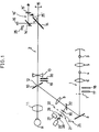
- Fig. 1 is a schematic drawing showing optical systems of a fundus blood vessel clogging apparatus according to a first embodiment of the present invention.
- Fig. 2 is a schematic sectional view showing the tissue structure of an eye fundus according to the present invention.
- Fig. 3 is a schematic drawing showing optical systems of a fundus blood vessel clogging apparatus according to a second embodiment of the present invention.
- Fig. 4 is a plan view showing a pattern plate of Fig. 3.
- Fig. 1 shows an embodiment of a method for clogging blood vessels of an eye fundus and an apparatus, which is applied to a fundus camera, for clogging the blood vessels.
- reference numeral 1 designates an illuminating optical system of the fundus camera
- reference numeral 2 designates a photographic optical system thereof.
- the illuminating optical system 1 includes a halogen lamp 3 and a xenon tube 4.
- the halogen lamp 3 is conjugate to the xenon tube 4 with respect to a condenser lens 5.
- the illumination light of the halogen lamp 3 and that of the xenon tube 4 are condensed by a condenser lens 6 and then are guided to a reflecting mirror 8 through an annular diaphragm 7.
- a laser diode may be used instead of the halogen lamp 3.
- the illumination light reflected by the reflecting mirror 8 passes through a relay lens 9, is then reflected by a perforated mirror 10, is guided to the eye fundus R of a subject through an objective lens 11, and illuminates the eye fundus R.
- the light beam from the eye fundus R passes through the objective lens 11 and is then guided to a focusing lens 13 through a hole 12 of the perforated mirror 10.
- a quick return mirror 14 is disposed behind the focusing lens 13. When a photograph is taken with a film (i.e., when a still image is recorded), the quick return mirror 14 is removed from the optical path of the photographic optical system 2. An image of the fundus is formed on a film 15 by the focusing lens 13.
- the light beam from the fundus R is reflected by the quick return mirror 14, and the fundus image is formed on a CCD 16.
- a signal output of the CCD 16 is converted into an image signal by an image processing circuit (not shown), and the fundus image is formed on a TV monitor (not shown).
- a surgeon performs an operation, mentioned later, while observing the TV monitor.
- a fundus image may be observed by the use of a finder optical system 16' which is made up of a quick return mirror 14' and an eyepiece 15'. When the finder optical system 16' is not used, the quick return mirror 14' is placed out of the optical path of light reflected by the quick return mirror 14.
- an exciter filter 17 for visible fluorescence and an exciter filter 18 for infrared fluorescence are inserted into the optical path between the annular diaphragm 7 and the condenser lens 6.
- a barrier filter 19 for visible fluorescence and a barrier filter 20 for infrared fluorescence are inserted into the optical path between the perforated mirror 10 and the focusing lens 13 of the photographic optical system 2.
- the exciter filter 17 for visible fluorescence When the exciter filter 17 for visible fluorescence is inserted into the optical path of the illuminating optical system 1, green illumination light is guided to the fundus R, and the fundus R is illuminated with the green illumination light.
- the exciter filter 18 for infrared fluorescence when the exciter filter 18 for infrared fluorescence is inserted into the optical path of the illuminating optical system 1, red and infrared illumination light is guided to the fundus R, and the fundus R is illuminated therewith.
- the exciter filters 17, 18 are placed out of the optical path of the illuminating optical system 1
- the barrier filters 19, 20 are placed out of the optical path of the photographic optical system 2.
- the laser projection optical system 21 includes a laser light source 23.
- a source for emitting a laser beam having a wavelength range of visible light (wavelength of 664nm) is used as the laser light source 23.
- a selective diaphragm 24 is disposed in front of the laser light source 23. The selective diaphragm 24 is conjugate to the fundus R with respect to the objective lens 11.
- a shutter 25 is inserted between the CCD 16 and the quick return mirror 14 in accordance with the power of a laser beam.
- the shutter 25 has a function of preventing the CCD 16 from being burned by the reflection of a laser beam having a high power.
- a shutter 25' is inserted into the finder optical system 16'.
- the laser projection optical system 21 includes a laser light source 27 used for aiming.
- the laser light source 23 is conjugate to the laser light source 27 with respect to a half mirror 28.
- Relay lenses 29, 30 are disposed between the half mirror 28 and the reflecting optical member 22.
- the selective diaphragm 24 consists of diaphragms 31, 32 which differ in aperture diameter from each other. Either of the selective diaphragms 31, 32 is inserted between the relay lens 29 and the relay lens 30.
- a laser spot is formed on the fundus R in accordance with the diameter of an aperture of the selective diaphragm 24.
- a laser beam emitted by the laser light source 27 is designed to have a wavelength range within which the laser beam can pass through the barrier filter 20. In this embodiment, the wavelength of the laser light source 27 is of a green range.
- an infrared fluorescent agent called indocyaninegreen, of the following chemical formula (CHEMICAL FORMULA 5) is injected into the veins of the subject or is taken by the subject in advance.
- the infrared fluorescent agent circulates through the fundus and is then illuminated with excitation light having a specific wavelength which has passed through the exciter filter 18 for infrared fluorescence. Thereby, infrared fluorescence is emitted.
- the fundus R has a diseased part K1, such as neovascular vessels, as shown in Fig. 2, the infrared fluorescent agent remains in the diseased part K1. Thereby, the amount of fluorescence from the diseased part K1 becomes larger than that of fluorescence from around the diseased part K1. Therefore, the diseased part K1 shining brightly on a TV monitor can be located.
- This photosensitive substance is a tetrapyrrole derivative.
- Mono-L-aspartiru ⁇ chlorin/e6/4 sodium salt (Abbreviated Npe6), one of the tetrapyrrole derivatives, is accumulated together with the infrared fluorescent agent in the endothelium of blood vessels of the diseased part K1 such as neovascular vessels. Active oxygen is then generated by the projection of a laser beam having the wavelength of 664 nm thereonto, and thereby the blood vessels of th diseased.part K1 are clogged.
- CHEMICAL FORMULA 7 is a stereoisome of CHEMICAL FORMULA 6. It is preferable to use a chemical compound of this formula instead of CHEMICAL FORMULA 6. where n is 1 or 2.
- the photosensitive substances are mixed with the infrared fluorescent agent, and advantageously a mixture containing them is given to the subject by intravenous injection at a time.
- the laser light source 23 emits a lase beam having the wavelength of 664nm in order to cause the photosensitive substance to generate a photochemical change.
- a laser spot is formed on the fundus R ⁇ in accordance with the diameter of an aperture of the selective diaphragm 24.
- the laser power of the laser light source 23 can be regulated by a power regulator (not shown). It is desirable that the laser light source 23 is capable of making the laser oscillation with the projection intensity of 20 to 500 mW/cm 2 and with the full power of at least 500 mW.
- a laser beam is projected by aiming at a marker which is a region of infrared fluorescence shining brightly in the fundus R.
- the photosensitive substance is caused to generate a photochemical change. Consequently, neovascular vessels can be clogged without injuring normal tissues to the utmost.
- Fig. 3 shows a second embodiment of a fundus camera to which the present invention is applied.
- the fundus camera of the second embodiment is constructed such that a pattern plate 33 is disposed between the laser light source 27 for aiming and the half mirror 28, and the relay to the eye fundus R is made through relay lenses 34, 35.
- a star-shaped aiming pattern is projected onto the pattern plate 33.
- a construction may be employed in which the laser light source 27 for aiming is intermittently driven to flicker the aiming pattern.
- the method for clogging blood vessels of an eye fundus and the apparatus and medicine used for clogging the blood vessels have the advantage that only the blood vessels of a diseased part are clogged for a surgical treatment almost without injury to normal tissues.
Landscapes
- Health & Medical Sciences (AREA)
- Ophthalmology & Optometry (AREA)
- Life Sciences & Earth Sciences (AREA)
- Engineering & Computer Science (AREA)
- General Health & Medical Sciences (AREA)
- Physics & Mathematics (AREA)
- Veterinary Medicine (AREA)
- Biomedical Technology (AREA)
- Heart & Thoracic Surgery (AREA)
- Surgery (AREA)
- Public Health (AREA)
- Animal Behavior & Ethology (AREA)
- Vascular Medicine (AREA)
- Optics & Photonics (AREA)
- Nuclear Medicine, Radiotherapy & Molecular Imaging (AREA)
- Multimedia (AREA)
- Biophysics (AREA)
- Medical Informatics (AREA)
- Molecular Biology (AREA)
- Eye Examination Apparatus (AREA)
- Pharmaceuticals Containing Other Organic And Inorganic Compounds (AREA)
- Medicines That Contain Protein Lipid Enzymes And Other Medicines (AREA)
- Medicines Containing Antibodies Or Antigens For Use As Internal Diagnostic Agents (AREA)
- Laser Surgery Devices (AREA)
Abstract
Description
- This invention relates to a method, apparatus, and medicine for clogging blood vessels of an eye fundus.
- There is known a method for clogging blood vessels of an eye fundus. There is also known a photocoagulator used as an apparatus for clogging blood vessels of an eye fundus. In the photocoagulator, an infrared fluorescent agent, called indocyaninegreen, is injected into a subject. When the infrared fluorescent agent circulates through the blood vessels of the eye fundus of the subject, infrared rays of light for excitation are projected onto the eye fundus and, as a result, the infrared fluorescent agent is excited to emit fluorescence. While a region emitting the fluorescence is being observed, a diseased part, such as neovascular vessels of a choroid, in the depth of the eye fundus is specified. After that, a near-infrared semiconductor laser beam is projected onto the diseased part so as to coagulate and treat the diseased part.
- In this conventional method and apparatus, however, injury to normal tissues is unavoidable during the treatment because of photocoagulation. Therefore, it is expected to develop a fundus treating method by which a diseased part only is treated to the utmost without injury to normal tissues, and develop an apparatus and a medicine used for the treatment.
- The present invention was made in view of the foregoing. It is therefore an object of the present invention to provide a fundus vessel clogging method by which only a diseased part of an eye fundus is treated to the utmost without injuring normal tissues, an apparatus used for clogging the blood vessels, and a medicine to clog them.
- In order to achieve the object, a fundus vessel clogging method according to an aspect of the present invention includes the steps of furnishing a subject with a photosensitive substance which remains in a diseased part in the depth of the eye fundus where an infrared fluorescent agent remains and which undergoes a photochemical change in the diseased part by the use of a laser beam with a specific wavelength as well as furnishing the subject with the infrared fluorescent agent, specifying the diseased part in accordance with emission of infrared fluorescence, and projecting the laser beam with the specific wavelength onto the diseased part so that the photosensitive substance will produce a photochemical change, thereby clogging blood vessels of the diseased part in the depth of the eye fundus.
- In order to achieve the object, a fundus vessel clogging apparatus according to an aspect of the present invention includes an illuminating optical system for illuminating an eye fundus of a subject, who has been furnished with an infrared fluorescent agent, with infrared rays of light so as to excite the infrared fluorescent agent and emit infrared fluorescence, a photographic optical system for observing and photographing the eye fundus, and a projecting optical system for projecting a laser beam with a specific wavelength onto the subject who has been furnished with a photosensitive substance which undergoes a photochemical change by means of the laser beam. In the apparatus, the laser beam is projected onto the photosensitive substance and thereby blood vessels of the diseased part in the depth of the eye fundus are selectively clogged while a region emitting the infrared fluorescence is being observed.
- In order to achieve the object, a medicine according to an aspect of the present invention includes a mixture containing an infrared fluorescent agent and a photosensitive substance of the following general formula (CHEMICAL FORMULA 3):

- In order to achieve the object, a medicine according to another aspect of the present invention includes a mixture containing an infrared fluorescent agent and a photosensitive substance of the following general formula (CHEMICAL FORMULA 4):

- A fundus vessel clogging apparatus according to another aspect of the present invention is characterized in that a diseased part in the depth of an eye fundus is specified by infrarec fluorescence, and a laser beam with a specific wavelength is projected onto a photosensitive substance which accumulates in the diseased part and undergoes a photochemical change by means of the laser beam for the purpose of treatment for the diseased part.
- It is preferable to project an aiming laser beam which serves to distinguish a part where the laser beam is projected from a part where the infrared fluorescence emits in such a way as to superimpose the aiming laser beam upon the laser beam. More preferably, the aiming laser beam is intermittently projected.
- According to the present invention, the infrared fluorescent agent and the photosensitive substance remain in the diseased part. In this situation, the remaining of the photosensitive substance in the diseased part is larger than that of the infrared fluorescent agent therein. Therefore, the diseased part is observed and specified by the infrared fluorescent agent, and thereafter a laser beam with a wavelength by which the photosensitive substance produces a photochemical change is projected. Thereby, since only the photosensitive substance produces a photochemical change, an influence on normal tissues is avoided as much as possible, and accordingly the diseased part only can be treated. In this case, if a mixture containing an infrared fluorescent agent and a photosensitive substance is used as a medicine, intravenous injection into the subject can be given at a time.
- Fig. 1 is a schematic drawing showing optical systems of a fundus blood vessel clogging apparatus according to a first embodiment of the present invention.
- Fig. 2 is a schematic sectional view showing the tissue structure of an eye fundus according to the present invention.
- Fig. 3 is a schematic drawing showing optical systems of a fundus blood vessel clogging apparatus according to a second embodiment of the present invention.
- Fig. 4 is a plan view showing a pattern plate of Fig. 3.
- Fig. 1 shows an embodiment of a method for clogging blood vessels of an eye fundus and an apparatus, which is applied to a fundus camera, for clogging the blood vessels. In Fig. 1, reference numeral 1 designates an illuminating optical system of the fundus camera, and reference numeral 2 designates a photographic optical system thereof. The illuminating optical system 1 includes a halogen lamp 3 and a
xenon tube 4. The halogen lamp 3 is conjugate to thexenon tube 4 with respect to a condenser lens 5. The illumination light of the halogen lamp 3 and that of thexenon tube 4 are condensed by a condenser lens 6 and then are guided to a reflecting mirror 8 through an annular diaphragm 7. A laser diode may be used instead of the halogen lamp 3. - The illumination light reflected by the reflecting mirror 8 passes through a relay lens 9, is then reflected by a
perforated mirror 10, is guided to the eye fundus R of a subject through anobjective lens 11, and illuminates the eye fundus R. The light beam from the eye fundus R passes through theobjective lens 11 and is then guided to a focusinglens 13 through ahole 12 of theperforated mirror 10. Aquick return mirror 14 is disposed behind the focusinglens 13. When a photograph is taken with a film (i.e., when a still image is recorded), thequick return mirror 14 is removed from the optical path of the photographic optical system 2. An image of the fundus is formed on afilm 15 by the focusinglens 13. On the other hand, during observation, the light beam from the fundus R is reflected by thequick return mirror 14, and the fundus image is formed on aCCD 16. A signal output of theCCD 16 is converted into an image signal by an image processing circuit (not shown), and the fundus image is formed on a TV monitor (not shown). A surgeon performs an operation, mentioned later, while observing the TV monitor. In the case of visible fluorescence, a fundus image may be observed by the use of a finder optical system 16' which is made up of a quick return mirror 14' and an eyepiece 15'. When the finder optical system 16' is not used, the quick return mirror 14' is placed out of the optical path of light reflected by thequick return mirror 14. - In accordance with a photographic mode, an
exciter filter 17 for visible fluorescence and anexciter filter 18 for infrared fluorescence are inserted into the optical path between the annular diaphragm 7 and the condenser lens 6. Correspondingly to the insertion of theexciter filter 17 for visible fluorescence and theexciter filter 18 for infrared fluorescence into the optical path of the illuminating optical system 1, abarrier filter 19 for visible fluorescence and abarrier filter 20 for infrared fluorescence are inserted into the optical path between theperforated mirror 10 and the focusinglens 13 of the photographic optical system 2. When theexciter filter 17 for visible fluorescence is inserted into the optical path of the illuminating optical system 1, green illumination light is guided to the fundus R, and the fundus R is illuminated with the green illumination light. On the other hand, when theexciter filter 18 for infrared fluorescence is inserted into the optical path of the illuminating optical system 1, red and infrared illumination light is guided to the fundus R, and the fundus R is illuminated therewith. In a color photographic mode except the fluorescence photographic mode, theexciter filters barrier filters - In the optical path of the illuminating optical system 1, there is disposed a reflecting
optical member 22 which serves as a constituent part of a laser projectionoptical system 21 used for photocoagulation between the reflecting mirror 8 and the relay lens 9. In this embodiment, a half mirror is used as the reflectingoptical member 22. The laser projectionoptical system 21 includes alaser light source 23. Herein, a source for emitting a laser beam having a wavelength range of visible light (wavelength of 664nm) is used as thelaser light source 23. Aselective diaphragm 24 is disposed in front of thelaser light source 23. Theselective diaphragm 24 is conjugate to the fundus R with respect to theobjective lens 11. When a blood vessel clogging treatment is conducted, ashutter 25 is inserted between theCCD 16 and thequick return mirror 14 in accordance with the power of a laser beam. Theshutter 25 has a function of preventing theCCD 16 from being burned by the reflection of a laser beam having a high power. Likewise, a shutter 25' is inserted into the finder optical system 16'. The laser projectionoptical system 21 includes alaser light source 27 used for aiming. Thelaser light source 23 is conjugate to thelaser light source 27 with respect to ahalf mirror 28.Relay lenses half mirror 28 and the reflectingoptical member 22. - The
selective diaphragm 24 consists ofdiaphragms selective diaphragms relay lens 29 and therelay lens 30. When a treatment for clogging blood vessels of a diseased part is conducted, a laser spot is formed on the fundus R in accordance with the diameter of an aperture of theselective diaphragm 24. A laser beam emitted by thelaser light source 27 is designed to have a wavelength range within which the laser beam can pass through thebarrier filter 20. In this embodiment, the wavelength of thelaser light source 27 is of a green range. - Since color photography and visible fluorescence photography are not directly relevant to the present invention, an explanation thereof is omitted. Thus, infrared fluorescence photography will be explained.
- When the infrared fluorescence photography is carried out, an infrared fluorescent agent, called indocyaninegreen, of the following chemical formula (CHEMICAL FORMULA 5) is injected into the veins of the subject or is taken by the subject in advance.

- The infrared fluorescent agent circulates through the fundus and is then illuminated with excitation light having a specific wavelength which has passed through the
exciter filter 18 for infrared fluorescence. Thereby, infrared fluorescence is emitted. If the fundus R has a diseased part K1, such as neovascular vessels, as shown in Fig. 2, the infrared fluorescent agent remains in the diseased part K1. Thereby, the amount of fluorescence from the diseased part K1 becomes larger than that of fluorescence from around the diseased part K1. Therefore, the diseased part K1 shining brightly on a TV monitor can be located. Conventionally, an infrared laser beam has been projected, taking careful aim, onto the diseased part K1, and thereby the diseased part K1 has been coagulated. However, disadvantageously, this conventional photocoagulation method brings about an injury to normal tissues therearound. In the present invention, therefore, a photosensitive substance of the following constitutional formula (CHEMICAL FORMULA 6) is injected into the veins of the subject or is taken by the subject.
- This photosensitive substance is a tetrapyrrole derivative. Mono-L-aspartiru·chlorin/e6/4 sodium salt (Abbreviated Npe6), one of the tetrapyrrole derivatives, is accumulated together with the infrared fluorescent agent in the endothelium of blood vessels of the diseased part K1 such as neovascular vessels. Active oxygen is then generated by the projection of a laser beam having the wavelength of 664 nm thereonto, and thereby the blood vessels of th diseased.part K1 are clogged.
- The following formula (CHEMICAL FORMULA 7) is a stereoisome of CHEMICAL FORMULA 6. It is preferable to use a chemical compound of this formula instead of CHEMICAL FORMULA 6.

- The photosensitive substances are mixed with the infrared fluorescent agent, and advantageously a mixture containing them is given to the subject by intravenous injection at a time.
- As described above, the
laser light source 23 emits a lase beam having the wavelength of 664nm in order to cause the photosensitive substance to generate a photochemical change. When the diseased part K1 is treated, a laser spot is formed on the fundus R·in accordance with the diameter of an aperture of theselective diaphragm 24. The laser power of thelaser light source 23 can be regulated by a power regulator (not shown). It is desirable that thelaser light source 23 is capable of making the laser oscillation with the projection intensity of 20 to 500 mW/cm2 and with the full power of at least 500 mW. - In the laser projection
optical system 21, a laser beam is projected by aiming at a marker which is a region of infrared fluorescence shining brightly in the fundus R. Thereby, the photosensitive substance is caused to generate a photochemical change. Consequently, neovascular vessels can be clogged without injuring normal tissues to the utmost. - Fig. 3 shows a second embodiment of a fundus camera to which the present invention is applied. The fundus camera of the second embodiment is constructed such that a
pattern plate 33 is disposed between thelaser light source 27 for aiming and thehalf mirror 28, and the relay to the eye fundus R is made throughrelay lenses pattern plate 33. Thereby, a distinction can be easily drawn between a part where the laser beam is projected and a part where infrared fluorescence is emitted. In order to distinguish the two parts more easily, a construction may be employed in which thelaser light source 27 for aiming is intermittently driven to flicker the aiming pattern. - According to the present invention, the method for clogging blood vessels of an eye fundus and the apparatus and medicine used for clogging the blood vessels have the advantage that only the blood vessels of a diseased part are clogged for a surgical treatment almost without injury to normal tissues.
Claims (7)
- A method for clogging blood vessels of an eye fundus (R), characterized by the steps of:furnishing a subject with a photosensitive substance which remains in a diseased part (K1) in the depth of the eye fundus (R) where an infrared fluorescent agent remains and which undergoes a photochemical change by means of a laser beam with a specific wavelength as well as furnishing the subject with the infrared fluorescent agent;specifying the diseased part (K1) in accordance with emission of infrared fluorescence; andprojecting the laser beam with the specific wavelength onto the diseased part (K1) so that the photosensitive substance may produce a photochemical change, thereby clogging blood vessels of the diseased part (K1) in the depth of the eye fundus (R).
- An apparatus for clogging blood vessels of an eye fundus (R), characterized in that said apparatus comprises:an illuminating optical system (1) for illuminating an eye fundus (R) of a subject, who has been furnished with an infrared fluorescent agent, with infrared rays of light so as to excite the infrared fluorescent agent and emit infrared fluorescence;a photographic optical system (2) for observing and photographing the eye fundus (R); anda projecting optical system (21) for projecting a laser beam with a specific wavelength onto the subject who has been furnished with a photosensitive substance which undergoes a photochemical change by means of the laser beam;wherein the laser beam is projected onto the photosensitive substance and thereby blood vessels of the diseased part (K1) in the depth of the eye fundus (R) are selectively clogged while a region emitting the infrared fluorescence is being observed.
- A medicine including a mixture, the mixture comprising an infrared fluorescent agent and a photosensitive substance of the following general formula:

- A medicine including a mixture, the mixture comprising an infrared fluorescent agent and a photosensitive substance of the following general formula:

- An apparatus for clogging blood vessels of an eye fundus (R) characterized in that a diseased part (K1) in the depth of an eye fundus (R) is specified by infrared fluorescence, and a laser beam with a specific wavelength is projected onto a photosensitive substance which accumulates in the diseased part (K1) and undergoes a photochemical change by means of the laser beam for the purpose of treatment for the diseased part (K1).
- The apparatus of claim 5, characterized in that an aiming laser beam which serves to distinguish a part where the laser beam is projected from a part where the infrared fluorescence is emitted is projected onto the eye fundus (R) in such a way as to superimpose the aiming laser beam upon the laser beam.
- The apparatus of claim 6, characterized in that the aiming laser beam is intermittently projected.
Applications Claiming Priority (2)
| Application Number | Priority Date | Filing Date | Title |
|---|---|---|---|
| JP33195/96 | 1996-02-21 | ||
| JP03319596A JP3845469B2 (en) | 1996-02-21 | 1996-02-21 | Administration agent for occlusion of neovascularization of the fundus |
Publications (3)
| Publication Number | Publication Date |
|---|---|
| EP0791361A2 true EP0791361A2 (en) | 1997-08-27 |
| EP0791361A3 EP0791361A3 (en) | 1998-02-04 |
| EP0791361B1 EP0791361B1 (en) | 2006-05-03 |
Family
ID=12379710
Family Applications (1)
| Application Number | Title | Priority Date | Filing Date |
|---|---|---|---|
| EP97250041A Expired - Lifetime EP0791361B1 (en) | 1996-02-21 | 1997-02-21 | Medicine for clogging blood vessels of eye fundus |
Country Status (5)
| Country | Link |
|---|---|
| US (2) | US6128524A (en) |
| EP (1) | EP0791361B1 (en) |
| JP (1) | JP3845469B2 (en) |
| DE (1) | DE69735785T2 (en) |
| ES (1) | ES2259801T3 (en) |
Cited By (11)
| Publication number | Priority date | Publication date | Assignee | Title |
|---|---|---|---|---|
| EP0980680A1 (en) * | 1998-08-20 | 2000-02-23 | Kowa Company Ltd. | Ophthalmic treatment apparatus |
| WO2001017561A1 (en) * | 1999-09-10 | 2001-03-15 | Akorn, Inc. | Fluorescent dye angiography and dye-enhanced photocoagulation |
| WO2001060360A1 (en) * | 2000-02-17 | 2001-08-23 | Meiji Seika Kaisha Ltd. | Photodynamic therapy for selectively closing neovasa in eyeground tissue |
| WO2001035867A3 (en) * | 1999-11-19 | 2001-12-06 | Hampp Norbert | Ophthalmologic implant |
| US6351663B1 (en) | 1999-09-10 | 2002-02-26 | Akorn, Inc. | Methods for diagnosing and treating conditions associated with abnormal vasculature using fluorescent dye angiography and dye-enhanced photocoagulation |
| US6443976B1 (en) | 1999-11-30 | 2002-09-03 | Akorn, Inc. | Methods for treating conditions and illnesses associated with abnormal vasculature |
| US6944493B2 (en) | 1999-09-10 | 2005-09-13 | Akora, Inc. | Indocyanine green (ICG) compositions and related methods of use |
| EP1441743A4 (en) * | 2001-11-09 | 2009-02-25 | Eyetech Pharmaceuticals | Methods for treating ocular neovascular diseases |
| EP2301424A1 (en) * | 2009-09-29 | 2011-03-30 | OD-OS GmbH | Ophthalmoscope with a laser device |
| US8545020B2 (en) | 2006-07-07 | 2013-10-01 | Od-Os Gmbh | Ophthalmoscope including therapy beam targeting |
| US9055896B2 (en) | 2009-09-29 | 2015-06-16 | Od-Os Gmbh | Ophthalmoscope for observing an eye |
Families Citing this family (8)
| Publication number | Priority date | Publication date | Assignee | Title |
|---|---|---|---|---|
| US7431456B2 (en) * | 1996-10-31 | 2008-10-07 | Nidek Co., Ltd. | Fundus camera |
| US6494878B1 (en) * | 2000-05-12 | 2002-12-17 | Ceramoptec Industries, Inc. | System and method for accurate optical treatment of an eye's fundus |
| US20040116909A1 (en) * | 2002-12-11 | 2004-06-17 | Ceramoptec Industries Inc. | Multipurpose diode laser system for ophthalmic laser treatments |
| CN2885311Y (en) | 2006-01-18 | 2007-04-04 | 郑成福 | Via urethra prostate therapeutic equipment using photodynamic therapy |
| US10376711B2 (en) | 2003-03-14 | 2019-08-13 | Light Sciences Oncology Inc. | Light generating guide wire for intravascular use |
| JP5426026B2 (en) * | 2009-07-28 | 2014-02-26 | エフ・ホフマン−ラ・ロシュ・アクチェンゲゼルシャフト | Non-invasive in vivo optical imaging method |
| US10888376B2 (en) * | 2018-05-08 | 2021-01-12 | Convergent Laser Technologies | Surgical laser system |
| WO2026083202A1 (en) * | 2024-10-17 | 2026-04-23 | Alcon Inc. | Fragmentation patterns to facilitate removal of a crystalline lens |
Family Cites Families (7)
| Publication number | Priority date | Publication date | Assignee | Title |
|---|---|---|---|---|
| US3893447A (en) * | 1973-06-04 | 1975-07-08 | Univ Johns Hopkins | Simultaneous angiography of the separate retinal and choroidal circulations |
| DE3069080D1 (en) * | 1979-11-28 | 1984-10-04 | Lasag Ag | Observation device for eye-treatment |
| US4638801A (en) * | 1983-07-06 | 1987-01-27 | Lasers For Medicine | Laser ophthalmic surgical system |
| NL9200143A (en) * | 1992-01-27 | 1993-08-16 | Seehof Lab F & E Ges | METHOD FOR PREPARING AN ACTIVE AGENT FOR PHOTODYNAMIC THERAPY AND FOR DETERMINING A DIAGNOSIS, THERAPEUTIC AGENT AND DIAGNOSTIC CONTAINING THE ACTIVE AGENT AND PHARMACEUTICAL COMPOSITION |
| PL172480B1 (en) | 1992-11-20 | 1997-09-30 | Univ British Columbia | Composition for destroying or damaging the area of new vascularization PL PL |
| CA2536069C (en) * | 1994-03-14 | 2008-06-03 | Massachusetts Eye And Ear Infirmary | Use of green porphyrins in ocular diagnosis and therapy |
| JP2961074B2 (en) | 1995-09-06 | 1999-10-12 | 明治製菓株式会社 | Neovascular occlusive agents for photochemotherapy |
-
1996
- 1996-02-21 JP JP03319596A patent/JP3845469B2/en not_active Expired - Fee Related
-
1997
- 1997-02-21 DE DE69735785T patent/DE69735785T2/en not_active Expired - Lifetime
- 1997-02-21 ES ES97250041T patent/ES2259801T3/en not_active Expired - Lifetime
- 1997-02-21 US US08/804,191 patent/US6128524A/en not_active Ceased
- 1997-02-21 EP EP97250041A patent/EP0791361B1/en not_active Expired - Lifetime
-
2002
- 2002-10-03 US US10/262,880 patent/USRE39357E1/en not_active Expired - Fee Related
Cited By (16)
| Publication number | Priority date | Publication date | Assignee | Title |
|---|---|---|---|---|
| EP0980680A1 (en) * | 1998-08-20 | 2000-02-23 | Kowa Company Ltd. | Ophthalmic treatment apparatus |
| WO2001017561A1 (en) * | 1999-09-10 | 2001-03-15 | Akorn, Inc. | Fluorescent dye angiography and dye-enhanced photocoagulation |
| US6351663B1 (en) | 1999-09-10 | 2002-02-26 | Akorn, Inc. | Methods for diagnosing and treating conditions associated with abnormal vasculature using fluorescent dye angiography and dye-enhanced photocoagulation |
| US6944493B2 (en) | 1999-09-10 | 2005-09-13 | Akora, Inc. | Indocyanine green (ICG) compositions and related methods of use |
| WO2001035867A3 (en) * | 1999-11-19 | 2001-12-06 | Hampp Norbert | Ophthalmologic implant |
| US6443976B1 (en) | 1999-11-30 | 2002-09-03 | Akorn, Inc. | Methods for treating conditions and illnesses associated with abnormal vasculature |
| WO2001060360A1 (en) * | 2000-02-17 | 2001-08-23 | Meiji Seika Kaisha Ltd. | Photodynamic therapy for selectively closing neovasa in eyeground tissue |
| EP1441743A4 (en) * | 2001-11-09 | 2009-02-25 | Eyetech Pharmaceuticals | Methods for treating ocular neovascular diseases |
| US8545021B2 (en) | 2006-07-07 | 2013-10-01 | Od-Os Gmbh | Ophthalmoscope including virtual position patterning for therapy beam application |
| US8545020B2 (en) | 2006-07-07 | 2013-10-01 | Od-Os Gmbh | Ophthalmoscope including therapy beam targeting |
| US8545022B2 (en) | 2006-07-07 | 2013-10-01 | Od-Os Gmbh | Ophthalmoscope including therapy beam pulse information storage |
| WO2011038935A1 (en) * | 2009-09-29 | 2011-04-07 | Od-Os Gmbh | Ophthalmoscope having a laser device |
| EP2301424A1 (en) * | 2009-09-29 | 2011-03-30 | OD-OS GmbH | Ophthalmoscope with a laser device |
| US9055896B2 (en) | 2009-09-29 | 2015-06-16 | Od-Os Gmbh | Ophthalmoscope for observing an eye |
| US9532712B2 (en) | 2009-09-29 | 2017-01-03 | Od-Os Gmbh | Ophthalmoscope having a laser device |
| US10716704B2 (en) | 2009-09-29 | 2020-07-21 | Od-Os Gmbh | Ophthalmoscope having a laser device |
Also Published As
| Publication number | Publication date |
|---|---|
| US6128524A (en) | 2000-10-03 |
| JPH09224971A (en) | 1997-09-02 |
| EP0791361A3 (en) | 1998-02-04 |
| JP3845469B2 (en) | 2006-11-15 |
| USRE39357E1 (en) | 2006-10-17 |
| ES2259801T3 (en) | 2006-10-16 |
| DE69735785D1 (en) | 2006-06-08 |
| EP0791361B1 (en) | 2006-05-03 |
| DE69735785T2 (en) | 2007-05-10 |
Similar Documents
| Publication | Publication Date | Title |
|---|---|---|
| US6128524A (en) | Medicine for clogging blood vessels of eye fundus | |
| JP3850192B2 (en) | Fundus photographing device | |
| WO1993006770A1 (en) | Infrared fundus video angiography system | |
| US20130329189A1 (en) | Ophthalmologic photography apparatus | |
| US6640131B1 (en) | Device for photodynamic diagnosis or treatment | |
| JPH04158829A (en) | Retinal camera | |
| US5557349A (en) | Fundus camera for infrared fluorsein angiography | |
| JP3706447B2 (en) | Ophthalmic diagnostic treatment device | |
| JP4138133B2 (en) | Fundus camera | |
| JP2837417B2 (en) | Fundus camera | |
| JP2802356B2 (en) | Fundus camera | |
| JP2004081255A (en) | Fundus camera | |
| JP2808000B2 (en) | Ophthalmic equipment | |
| JP3102511B2 (en) | Ophthalmic equipment | |
| JP4357602B2 (en) | Fundus camera | |
| JPH1043139A (en) | Ophthalmic equipment | |
| JP3535609B2 (en) | Fundus camera | |
| JP2008017899A (en) | Fluorescence diagnostic method | |
| JP2612209B2 (en) | Fundus camera | |
| JPH10179522A (en) | Ophthalmic equipment | |
| JPH04352934A (en) | Ophthalmology imaging device | |
| JPH04367646A (en) | Ophthalmophotograhic device | |
| JP2000060800A (en) | Fundus camera | |
| JPH07163524A (en) | Fundus camera | |
| JP2000316812A (en) | Ophthalmic imaging equipment |
Legal Events
| Date | Code | Title | Description |
|---|---|---|---|
| PUAI | Public reference made under article 153(3) epc to a published international application that has entered the european phase |
Free format text: ORIGINAL CODE: 0009012 |
|
| 17P | Request for examination filed |
Effective date: 19970221 |
|
| AK | Designated contracting states |
Kind code of ref document: A2 Designated state(s): DE ES IT |
|
| PUAL | Search report despatched |
Free format text: ORIGINAL CODE: 0009013 |
|
| AK | Designated contracting states |
Kind code of ref document: A3 Designated state(s): DE ES IT |
|
| 17Q | First examination report despatched |
Effective date: 20010808 |
|
| RAP1 | Party data changed (applicant data changed or rights of an application transferred) |
Owner name: MEIJI SEIKA KAISHA, LTD. |
|
| GRAP | Despatch of communication of intention to grant a patent |
Free format text: ORIGINAL CODE: EPIDOSNIGR1 |
|
| RTI1 | Title (correction) |
Free format text: MEDICINE FOR CLOGGING BLOOD VESSELS OF EYE FUNDUS |
|
| GRAS | Grant fee paid |
Free format text: ORIGINAL CODE: EPIDOSNIGR3 |
|
| GRAA | (expected) grant |
Free format text: ORIGINAL CODE: 0009210 |
|
| AK | Designated contracting states |
Kind code of ref document: B1 Designated state(s): DE ES IT |
|
| PG25 | Lapsed in a contracting state [announced via postgrant information from national office to epo] |
Ref country code: IT Free format text: LAPSE BECAUSE OF FAILURE TO SUBMIT A TRANSLATION OF THE DESCRIPTION OR TO PAY THE FEE WITHIN THE PRE;WARNING: LAPSES OF ITALIAN PATENTS WITH EFFECTIVE DATE BEFORE 2007 MAY HAVE OCCURRED AT ANY TIME BEFORE 2007. THE CORRECT EFFECTIVE DATE MAY BE DIFFERENT FROM THE ONE RECORDED.SCRIBED TIME-LIMIT Effective date: 20060503 |
|
| REF | Corresponds to: |
Ref document number: 69735785 Country of ref document: DE Date of ref document: 20060608 Kind code of ref document: P |
|
| REG | Reference to a national code |
Ref country code: ES Ref legal event code: FG2A Ref document number: 2259801 Country of ref document: ES Kind code of ref document: T3 |
|
| PLBE | No opposition filed within time limit |
Free format text: ORIGINAL CODE: 0009261 |
|
| STAA | Information on the status of an ep patent application or granted ep patent |
Free format text: STATUS: NO OPPOSITION FILED WITHIN TIME LIMIT |
|
| 26N | No opposition filed |
Effective date: 20070206 |
|
| PGFP | Annual fee paid to national office [announced via postgrant information from national office to epo] |
Ref country code: DE Payment date: 20110216 Year of fee payment: 15 Ref country code: IT Payment date: 20110216 Year of fee payment: 15 |
|
| PGFP | Annual fee paid to national office [announced via postgrant information from national office to epo] |
Ref country code: ES Payment date: 20110218 Year of fee payment: 15 |
|
| REG | Reference to a national code |
Ref country code: DE Ref legal event code: R082 Ref document number: 69735785 Country of ref document: DE Representative=s name: KANZLEI PFENNING, MEINIG & PARTNER GBR, DE |
|
| REG | Reference to a national code |
Ref country code: DE Ref legal event code: R082 Ref document number: 69735785 Country of ref document: DE Representative=s name: KANZLEI PFENNING, MEINIG & PARTNER GBR, DE Effective date: 20120210 Ref country code: DE Ref legal event code: R081 Ref document number: 69735785 Country of ref document: DE Owner name: MEIJI SEIKA PHARMA CO., LTD., JP Free format text: FORMER OWNER: MEIJI SEIKA KAISHA LTD., TOKIO/TOKYO, JP Effective date: 20120210 |
|
| PG25 | Lapsed in a contracting state [announced via postgrant information from national office to epo] |
Ref country code: IT Free format text: LAPSE BECAUSE OF NON-PAYMENT OF DUE FEES Effective date: 20120221 |
|
| REG | Reference to a national code |
Ref country code: DE Ref legal event code: R119 Ref document number: 69735785 Country of ref document: DE Effective date: 20120901 |
|
| PG25 | Lapsed in a contracting state [announced via postgrant information from national office to epo] |
Ref country code: DE Free format text: LAPSE BECAUSE OF NON-PAYMENT OF DUE FEES Effective date: 20120901 |
|
| REG | Reference to a national code |
Ref country code: ES Ref legal event code: FD2A Effective date: 20130708 |
|
| PG25 | Lapsed in a contracting state [announced via postgrant information from national office to epo] |
Ref country code: ES Free format text: LAPSE BECAUSE OF NON-PAYMENT OF DUE FEES Effective date: 20120222 |