EP0790672A1 - Connector apparatus - Google Patents
Connector apparatus Download PDFInfo
- Publication number
- EP0790672A1 EP0790672A1 EP97300208A EP97300208A EP0790672A1 EP 0790672 A1 EP0790672 A1 EP 0790672A1 EP 97300208 A EP97300208 A EP 97300208A EP 97300208 A EP97300208 A EP 97300208A EP 0790672 A1 EP0790672 A1 EP 0790672A1
- Authority
- EP
- European Patent Office
- Prior art keywords
- connector apparatus
- optical fiber
- portions
- cable
- magnet
- Prior art date
- Legal status (The legal status is an assumption and is not a legal conclusion. Google has not performed a legal analysis and makes no representation as to the accuracy of the status listed.)
- Withdrawn
Links
- 239000013307 optical fiber Substances 0.000 claims abstract description 100
- 230000005540 biological transmission Effects 0.000 claims abstract description 73
- 230000002093 peripheral effect Effects 0.000 description 22
- 230000008054 signal transmission Effects 0.000 description 12
- 230000005291 magnetic effect Effects 0.000 description 9
- 238000004891 communication Methods 0.000 description 6
- 230000003287 optical effect Effects 0.000 description 6
- 239000000696 magnetic material Substances 0.000 description 4
- 238000000034 method Methods 0.000 description 4
- 229920003002 synthetic resin Polymers 0.000 description 4
- 239000000057 synthetic resin Substances 0.000 description 4
- 239000000463 material Substances 0.000 description 3
- 230000002787 reinforcement Effects 0.000 description 3
- XEEYBQQBJWHFJM-UHFFFAOYSA-N Iron Chemical compound [Fe] XEEYBQQBJWHFJM-UHFFFAOYSA-N 0.000 description 2
- 230000006378 damage Effects 0.000 description 2
- 230000007547 defect Effects 0.000 description 2
- 238000013461 design Methods 0.000 description 2
- 230000000694 effects Effects 0.000 description 2
- 239000000835 fiber Substances 0.000 description 2
- 230000006870 function Effects 0.000 description 2
- 238000007493 shaping process Methods 0.000 description 2
- 229910000640 Fe alloy Inorganic materials 0.000 description 1
- 208000027418 Wounds and injury Diseases 0.000 description 1
- 230000002411 adverse Effects 0.000 description 1
- 238000005253 cladding Methods 0.000 description 1
- 230000008878 coupling Effects 0.000 description 1
- 238000010168 coupling process Methods 0.000 description 1
- 238000005859 coupling reaction Methods 0.000 description 1
- 239000003302 ferromagnetic material Substances 0.000 description 1
- 230000036039 immunity Effects 0.000 description 1
- 230000010365 information processing Effects 0.000 description 1
- 208000014674 injury Diseases 0.000 description 1
- 239000006247 magnetic powder Substances 0.000 description 1
- 230000014759 maintenance of location Effects 0.000 description 1
- 239000002184 metal Substances 0.000 description 1
- 229910052751 metal Inorganic materials 0.000 description 1
- 238000012986 modification Methods 0.000 description 1
- 230000004048 modification Effects 0.000 description 1
- 238000000465 moulding Methods 0.000 description 1
- 229910000889 permalloy Inorganic materials 0.000 description 1
- 230000035699 permeability Effects 0.000 description 1
- 238000012545 processing Methods 0.000 description 1
- 239000011253 protective coating Substances 0.000 description 1
- 230000003014 reinforcing effect Effects 0.000 description 1
- 230000001131 transforming effect Effects 0.000 description 1
Images


Classifications
-
- H—ELECTRICITY
- H01—ELECTRIC ELEMENTS
- H01R—ELECTRICALLY-CONDUCTIVE CONNECTIONS; STRUCTURAL ASSOCIATIONS OF A PLURALITY OF MUTUALLY-INSULATED ELECTRICAL CONNECTING ELEMENTS; COUPLING DEVICES; CURRENT COLLECTORS
- H01R13/00—Details of coupling devices of the kinds covered by groups H01R12/70 or H01R24/00 - H01R33/00
- H01R13/62—Means for facilitating engagement or disengagement of coupling parts or for holding them in engagement
- H01R13/6205—Two-part coupling devices held in engagement by a magnet
-
- G—PHYSICS
- G02—OPTICS
- G02B—OPTICAL ELEMENTS, SYSTEMS OR APPARATUS
- G02B6/00—Light guides; Structural details of arrangements comprising light guides and other optical elements, e.g. couplings
- G02B6/24—Coupling light guides
- G02B6/42—Coupling light guides with opto-electronic elements
- G02B6/4201—Packages, e.g. shape, construction, internal or external details
- G02B6/4246—Bidirectionally operating package structures
-
- G—PHYSICS
- G02—OPTICS
- G02B—OPTICAL ELEMENTS, SYSTEMS OR APPARATUS
- G02B6/00—Light guides; Structural details of arrangements comprising light guides and other optical elements, e.g. couplings
- G02B6/24—Coupling light guides
- G02B6/36—Mechanical coupling means
- G02B6/38—Mechanical coupling means having fibre to fibre mating means
- G02B6/3807—Dismountable connectors, i.e. comprising plugs
- G02B6/3873—Connectors using guide surfaces for aligning ferrule ends, e.g. tubes, sleeves, V-grooves, rods, pins, balls
- G02B6/3886—Magnetic means to align ferrule ends
-
- H—ELECTRICITY
- H01—ELECTRIC ELEMENTS
- H01L—SEMICONDUCTOR DEVICES NOT COVERED BY CLASS H10
- H01L31/00—Semiconductor devices sensitive to infrared radiation, light, electromagnetic radiation of shorter wavelength or corpuscular radiation and specially adapted either for the conversion of the energy of such radiation into electrical energy or for the control of electrical energy by such radiation; Processes or apparatus specially adapted for the manufacture or treatment thereof or of parts thereof; Details thereof
- H01L31/02—Details
- H01L31/0232—Optical elements or arrangements associated with the device
-
- H—ELECTRICITY
- H04—ELECTRIC COMMUNICATION TECHNIQUE
- H04B—TRANSMISSION
- H04B10/00—Transmission systems employing electromagnetic waves other than radio-waves, e.g. infrared, visible or ultraviolet light, or employing corpuscular radiation, e.g. quantum communication
- H04B10/11—Arrangements specific to free-space transmission, i.e. transmission through air or vacuum
- H04B10/112—Line-of-sight transmission over an extended range
- H04B10/1123—Bidirectional transmission
Definitions
- This invention relates to a connector apparatus. More particularly, it relates to a connector apparatus for interconnecting at least two electronic equipments.
- the radio transmission technique for transmitting data signals exploiting infrared rays is extensively applied for remote control of video or audio equipment such as a television receiver or tape recorder.
- this sort of the radio signal transmission technique is also applied as a transmission technique for data signals for interconnecting a main computer unit and its peripheral or terminal devices.
- the design statement for this sort of the signal transmission technique is prescribed as Infra-red Data Association (IrDA) standard.
- the radio signal transmission system under the IrDA standard is characterized by low output, directivity with the center angle of 15°, short-range communication up to 1 m and one-for-one or one-for-N inter-equipment interconnection. Therefore, the radio signal transmission based on the IrDA standard has a number of meritorious effects, such that data transmission can be done easily by installing the equipments loaded with the corresponding functions in proximity to each other, that painstaking interconnection operations or mistaken interconnections may be eliminated, that spatial efficiency may be improved by eliminating numerous connection cables, and that power source processing can be simplified by electrically separating the equipments from one another.
- the equipment conforming to the IrDA standard, as described above, include an IR emitting devices and PIN photodiodes (light-receiving elements) as a light-emitting module and as a light receiving element, respectively, and a data transmission/reception unit in a casing of the equipment for facing the light-emitting and light-receiving elements.
- the transmission unit of the data transmission/reception device includes, along with the light emitting element for converting an electrical signal into a light signal and outputting the resulting light signal, a modulator for transforming data signals transmitted from a communication controller UART into electrical signals and a transmission/.reception circuit for driving the light emitting element.
- the receiving unit of the data transmission/reception device is made up of the light receiving element for transferring a light signal into an electrical signal and a reception circuit for amplifying and wave-shaping the photoelectrical signal received by the light receiving element.
- a state devoid of IR signal is defined as ⁇ 1', while a state in which an IR pulse of 1.6 s to 3/16 bit time has been detected is defined as ⁇ 0'. Therefore, the receiving unit includes an IR filter for reducing white noise, removing optical noise, such as IR light of a non-specified wavelength or extraneous light, and for correctly detecting the specified IR rays.
- a computer system is made up of a main computer unit 1 and plural peripheral devices, such as a monitor 2, a keyboard 3, a printer 4 or an external memory 5, as shown in Fig.1, and data signals can be transmitted between these unit or devices.
- peripheral devices such as a monitor 2, a keyboard 3, a printer 4 or an external memory 5, as shown in Fig.1
- data signals can be transmitted between these unit or devices.
- various system equipments are usually interconnected by a connector cable, such that a number of connection cables are required to deteriorate the spatial efficiency, while raising various inconveniences, such as mistaken interconnections.
- transmission of data signals between the unit or devices making up the system can be performed without using connection cables by exploiting the radio signal transmission system for data signals employing infrared rays based on the above-described IrDA standard, as shown in Fig.1.
- the radio signal transmission system for data signals has such defects that the data signal transmission distance is as short as approximately 1 m, power consumption is large and the system is weak against optical noise.
- the radio signal transmission system for data signals based on the IrDA standard, has an additional defect that, since there is no means for confirming that data transmission is being performed correctly between the unit or devices, the user feels uneasy as to whether or not data communication is actually proceeding correctly.
- the above-described computer system has a drawback that the unit or devices are placed on respective table in a disorderly state, such that, if documents or files are placed between the main computer unit 1 and the peripheral devices or if the user extends his or her hand or arm into the space between the unit and the peripheral devices , data signal transmission is interrupted transiently.
- the present invention provides a connector apparatus for interconnecting at least two electronic equipments each having an input/output unit including a transmission portion and a reception portion for enabling data transmission/reception between the electronic equipments.
- the connector apparatus includes at least a cable and a pair of connecting portions provided at both ends of the cable.
- Each connecting portion has a magnet portion for being attracted by the equipment and a limiting portion for limiting the rotational position at the time of connection thereof to the equipments.
- the present invention provides a connector apparatus for interconnecting at least two electronic equipments each having an input/output unit including a transmission portion and a reception portion for enabling data transmission/reception between the electronic equipments.
- the connector apparatus includes at least two cables and a pair of connecting portions for holding both ends of the cables, each connecting portion having a magnet portion for being attracted by the equipment and a limiting portion for limiting the rotational position at the time of connection thereof to the equipments.
- the present invention provides a connector apparatus for interconnecting at least two electronic equipments each having an input/output unit including a light emitting portion and a light receiving portion for enabling data transmission/reception between the electronic equipments.
- the connector apparatus includes at least two optical fibers and a pair of connecting portions for holding both ends of the optical fibers, each connecting portion having a magnet portion for being attracted by the equipment and a limiting portion for limiting the rotational position at the time of connection thereof to the equipments. With the ends of the optical fibers connected by the connecting portions to the electronic equipments, the ends of the optical cables are held at positions facing the input/output unit.
- Fig.1 shows a structure of a computer system exploiting the radio signal transmission system for data signals exploiting infrared rays in accordance with the IrDA standard.
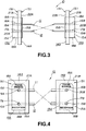
- Fig.2 is a schematic exploded perspective view for illustrating the connector apparatus according to the present invention.
- Fig.3 is a schematic side view showing the connector apparatus shown in Fig.2.
- Fig.4 is a schematic front view showing the connector apparatus shown in Fig.2.
- Fig.5 is a schematic longitudinal cross-sectional view showing a connector apparatus according to a second embodiment of the present invention.
- Fig.6 is a schematic front view showing the connector apparatus shown in Fig.2.
- Fig.7 is a schematic longitudinal cross-sectional view showing a connector apparatus according to a third embodiment of the present invention.
- Fig.8 is a schematic front view showing a a connector apparatus according to a fourth embodiment of the present invention.
- Fig.9 is a schematic front view showing a modification of a connector apparatus according to the present invention.
- a connector apparatus for interconnecting electronic equipments such as a personal computer and a printer as a peripheral device, is taken as an example.
- the connector apparatus embodying the present invention is connected to two electronic equipments 30, 30 constructed in accordance with design statements conforming to the IrDA standard for enabling exchange of data signals between these equipments 30, 30 in accordance with the IrDA standard.
- Figs.2 to 4 illustrate a first embodiment of the present invention in which a connector apparatus 10 is made up of a pair of optical fibers 11, 12, a pair of fitting members 13A, 13B in which are inserted and secured both ends 19, 20 of the optical fibers 11, 12, and a pair of magnet members 14A, 14B.
- the fitting members 13A, 13B constitute fitting means fitted to a data transmission/reception unit 30A of each equipment 30.
- optical fibers 11, 12 multi-mode optical fibers 50 to 100 m in diameter, frequently used for transmission of data signals in general, are used.
- Each of the optical fibers 11, 12 is made up of a core and a cladding surrounding the outer periphery of the core, in a known manner.
- the light entering one ends 19A, 20A of the optical fibers 19, 20 are conducted in the optical fibers 19, 20 substantially without leakage to outside so as to be radiated at the opposite ends 19B, 20B.
- the optical fibers 11, 12 are sufficiently flexible over their entire lengths.
- the optical fibers 11, 12 may have their outer peripheral surfaces covered with a protective coating.
- Each of the fitting members 13A, 13B is molded from an electrically insulating synthetic resin material substantially in the shape of a rectangular block, and has a major surface 15A and an opposite side major surface 15B though which are bored first optical fiber fitting holes 16A, 16B and second optical fiber fitting holes 17A, 17B spaced apart from the holes 16A, 16B in the longitudinal direction (in the up-and-down direction in Figs.2 and 3).
- Each of these fitting members 13A, 13B has a longitudinal lateral side 18A formed as an arcuately-contoured peripheral surface and an opposite lateral side 18B formed as a planar peripheral surface, thus presenting a substantially horse-shoe shape non-symmetrical with respect to the longitudinal direction, as shown in Fig.2.
- the fitting member 13A With the fitting member 13A, the first fitting hole 16A of the arcuately-contoured peripheral lateral surface 18A is used for transmission, while the second fitting hole 17A of the planar peripheral lateral surface 18B is used for reception, as shown in Fig.4.
- the fitting member 13B With the fitting member 13B, the first fitting hole 16B of the arcuately-contoured peripheral lateral surface 18A is used for transmission, while the second fitting hole 17B of the planar peripheral lateral surface 18B is used for reception, as shown in Fig.4.
- the lateral sides 18A, 18B of the fitting member 13A in the longitudinal direction constitute portions setting the relative position of the optical fibers 11, 12 with respect to a light emitting element 35 and a light receiving element 36 of an electronic equipment 30, as will be explained subsequently.
- the outer peripheral edges of the major surfaces 15A of the fitting members 13A, 13B are chamfered so as to operate for guiding the fitting members when the fitting members are fitted into the data transmission/reception unit 30A of the electronic equipment 30, as will be explained subsequently.
- both ends 19, 20 of the optical fibers 11, 12 are introduced from the major surfaces 15B into the first fitting holes 16A, 16B and the second fitting holes 17A, 17B to the side of the opposite major surfaces 15A so as to be secured in position.
- the ends 19A, 19B, 20A and 20B of the optical fibers 11, 12 are exposed to outside at the major surfaces 15A.
- the end 19A of the optical fiber 11 is inserted and secured in the first fitting hole 16A of the arcuately-contoured lateral surfaces 18A of the fitting member 13A, while the end 20A of the opposite side optical fiber 12 is inserted and secured in the second fitting hole 17A of the planar lateral surfaces 18B thereof, as shown in Figs.3 and 4.
- the optical fibers 11, 12 are twisted partway so as to be guided from the fitting member 13A towards the opposite side fitting member 13B so that the ends 19A, 19B, 20A and 20B thereof are inserted and held in the first fitting holes 16A, 16B and in the second fitting holes 17A, 17B, respectively, as shown in Figs.3 and 4.
- the end 20B of the optical fiber 12 is inserted and held in the first fitting hole 16A of the arcuately-contoured lateral side 18A of the fitting member 13B, as shown in Figs.3 and 4.
- the end 19B of the optical fiber 11 is inserted and held in the first fitting hole 17B of the planar lateral side 18B of the fitting member 13B, as shown in Figs.3 and 4.
- the ends 19A, 19B, 20A and 20B of the optical fibers 11, 12 are held and secured by the fitting members 13A, 13B so that the arcuately-contoured lateral sides 18A and the planar lateral side 18B serve as the transmission side end and as the reception side end, respectively.
- the fitting members 13A, 13B are fitted to the data transmission/reception unit 30A of the electronic equipment 30, as later explained, the arcuately-contoured lateral sides 18A and the planar lateral side 18B of the fitting members 13A, 13B constitute position setting portions for setting the relative positions of the optical fibers 11, 12.
- position setting portions inhibit rotation of the fitting members 13A, 13B when the fitting members 13A, 13B are fitted to the data transmission/reception unit 30A, as indicated by arrow A in Figs.2 and 4.
- the position setting portions set the orientation of the fitting members 13A, 13B in the up-and-down direction.
- the indication ⁇ transmission ⁇ and ⁇ reception ⁇ is inscribed on the major surfaces 15A of the fitting members 13A, 13B in association with the first fitting holes 16A, 16B and the second fitting holes 17A, 17B, respectively, as shown in Fig.4.
- the magnet members 14A, 14B are larger in outer size and thinner in thickness than the fitting members 13A, 13B, respectively, and are unified to the fitting members 13A, 13B by outsert molding. Therefore, the magnet members 14A, 14B constitute flanges extended on the entire outer rim portions thereof beyond the outer periphery of the fitting portions 13A, 13B, respectively. These magnet members 14A, 14B are magnetized in the direction of thickness thereof so that the magnetic polarities of the magnet member 14A associated with the fitting member 13A are reversed from those of the magnet member 14B associated with the fitting member 13B.
- the magnet member 14A associated with the magnet member 13A has its major surface 21A magnetized to an N polarity, while having its opposite side major surface 21B magnetized to an S polarity.
- the magnet member 14B associated with the magnet member 13B has its major surface 21A magnetized to an S polarity, while having its opposite side major surface 21B magnetized to an N polarity.
- the magnet members 14A, 14B may be molded in a frame shape as distinct members from the fitting members 13A, 13B and secured to the outer periphery of the fitting members 13A, 13B. In this case, the magnet members 14A, 14B are molded to the same shape and in a 180° rotated position to the fitting members 13A, 13B.
- the magnet members 14A, 14B may be formed as plates each having a pair of through-holes traversed by the optical fibers 11, 12 and secured to the major surfaces 15B of the fitting members 13A, 13B.
- the magnet members 14A, 14B are magnetized so that the mutually facing major surfaces 22A, 22B and the mutually opposite major surfaces 21A, 21B are of opposite polarities, the magnet members can be magnetically assembled and secured together by abutting the major surfaces 21A, 21B or the major surfaces 22A, 22B together when the connector apparatus 10 is not in use.
- the connector apparatus 10 can be assembled together compactly without the necessity of using a fastener or the like so that there is no risk of an unneeded force being applied to the connector apparatus thus possibly destructing the optical fibers 11, 12.
- the equipment 30 making up the computer system such as a main computer unit 1 or the peripheral devices 2 to 5, has mounted on a portion of a casing 31 thereof the data transmission/reception unit 30A on which is loaded the above-described connector apparatus 10, as shown in Fig.2.
- This data transmission/reception unit 30A is made up of a casing 31, having a fitting hole 32, a circuit board 34 mounted within the casing 31, a data transmission board 35 mounted on the circuit board 34, a light emitting element 36 and a light receiving element 37 loaded on the data transmission board 35, and an infrared filter 38.
- the casing 31 constituting the data transmission/reception unit 30A of the equipment 30 is formed of a magnetic material, such as by a metallic plate.
- a magnetic material is classified into a ferromagnetic material which is magnetized by an external magnetic field with less ease but which, once magnetized, continues to be magnetized even on removal of the external magnetic field, and a soft magnetic material which is magnetized with ease by the external magnetic field and which is readily demagnetized on removal of the external magnetic field.
- the casing 31 is formed of soft magnetic material having high magnetic permeability and low coercivity, such as soft iron or permalloy.
- the entire casing 31 may be formed of a non-magnetic synthetic resin material and at least the data transmission/reception unit 30A may be insert-molded or otherwise affixed to the casing 31.
- the fitting hole 32 is formed in the casing 31 so as to be substantially coextensive as the outer shape of the fitting member 13 of the connector apparatus 10.
- the fitting hole 32 is generally elongated and horse-shoe shaped in the longitudinal direction and has an inner lateral side 33A in the longitudinal direction thereof formed as an arcuately-contoured surface and an opposite side inner lateral surface 33B in the same longitudinal direction formed as a planar surface, as shown in Fig.2.
- the fitting hole 32 permits the connector apparatus 10 to be connected to the equipment 30 only when one of the fitting members 13A, 13B is inserted therein in the correct position.
- the fitting hole 32 may be constituted as a bottomed recess for holding the data transmission board 35 on the recessed bottom.
- the fitting hole 32 may be designed to hold the light emitting element 36 and the light receiving element 37 on its bottom.
- the casing 31 has a reinforcement rib 39 formed on the entire rim portion of the inner surface extending along the opening edge of the fitting hole 32, as shown in Fig.2.
- This reinforcement rib 39 operates for reinforcing the opening of the fitting hole 32 and for permitting the fitting members 13A, 13B to be fitted in the fitting hole 32 in stable state.
- the reinforcement rib 39 may be formed by plural ribs partially protuberantly formed along the opening edge of the fitting hole 32.
- the circuit board 34 is constituted by a circuit board having loaded thereon a control circuit or a transmission circuit of the equipment 30.
- the circuit transmission board 35 is arranged at an end of the circuit board 34 proximate to the inner surface of the casing 31.
- the data transmission board 35 is sized to close the fitting hole 32 and set upright on the circuit board 34 for facing the fitting hole 32.
- the data transmission board 35 has mounted thereon the light emitting element 36 and the light receiving element 37 facing outside via the fitting hole 32.
- a modulation circuit for converting data signals sent from the transmission controller UART of the equipment 30, not shown, into electrical signals, and a transmission circuit designed for driving the light emitting element 36.
- the modulation circuit and the transmission circuit are connected to the light emitting element 36.
- a reception circuit not shown, connected to the light receiving element 37 for amplifying and wave-shaping photo-electric data signals received by the light receiving element 37.
- the above-mentioned circuits may also be mounted on the circuit board 34.
- the above-mentioned circuits may also be directly mounted on the circuit board 34 via terminals, not shown, with the light emitting element 36 and the light receiving element 37 facing the fitting hole 32.
- the IR filter 38 is arranged on the inner surface of the casing 31 for closing the fitting hole 32.
- the IR filter 38 is mounted with respect to the light receiving element 37 for reducing the white noise or cutting optical noise, such as IR light of a non-specified wavelength or extraneous light, and for correctly detecting the specified IR rays.
- the casing 31 is formed by, for example, a metallic plate
- the IR filter 38 may be secured to the inner surface of the metal plate or assembled thereto via a magnet holder.
- the casing 31 is molded from a synthetic resin, the IR filter 38 is assembled to a metallic plate having a fitting hole 32 and which is unified to the casing 31.
- the connector apparatus 10 is connected to the equipments 30 by having the fitting member 13 fitted in the fitting hole 32 formed in the data transmission/reception unit 30A. In this case, the connector apparatus 10 can be inserted into the data transmission/reception unit 30A only when the fitting member 13 fits into the fitting hole 32.
- the connector apparatus 10 is loaded on the equipments 30 with the fitting member 13A fitting in the fitting hole 32 under the magnetic force of the magnet member 14A acting on the casing 31, as shown for example in Fig.2.
- the fitting member 13A faces the data transmission board 34 via the IR filter 38.
- the fitting member 13A is connected to the data transmission/reception unit 30A of the main computer unit 1 shown in Fig.1, while its other fitting member 13B is connected to the data transmission/reception unit 30A of the printer 4.
- the one end 19A of the first optical fiber 11 of the fitting member 13A faces the light emitting element 36 of the main computer unit 1, while the opposite end 20A of the second optical fiber 12 of the opposite side fitting member 13B faces the light receiving element 37.
- the opposite side end 19B of the first optical fiber 11 of the opposite side fitting member 13B faces the light receiving element 37 of the printer 4, while the opposite side end 20B of the second optical fiber 12 faces the light emitting element 36.
- the light emitting element 36 of the main computer unit 1 is turned on and off based on the data signals for conducting the outgoing infrared light via the end 19A into the inside of the first optical fiber 11.
- the infrared light derived from the data signals is conducted through the inside of the first optical fiber 11 efficiently without optical loss to the opposite end 19B so as to be radiated to outside.
- the infrared light is received by the light receiving element 37 on the printer 4.
- the connector apparatus 10 if data signal are transmitted from the printer 4 to the main computer unit 1, the light emitting element 36 of the printer 4 is turned on and off based on the data signals for conducting the outgoing infrared light via the end 20B into the inside of the first optical fiber 11.
- the infrared light derived from the data signals is conducted through the inside of the first optical fiber 11 efficiently without optical loss to the end 20A so as to be radiated to outside.
- the infrared light is received by the light receiving element 37 on the main computer unit 1.
- the connector apparatus 10 permits the data signals to be transmitted in this manner between the main computer unit 1 and the printer 4 by the fitting members 13A, 13B provided on both sides of the connector apparatus 10 being fitted to the data transmission/reception unit 30A of the printer 4.
- a connector apparatus 50 according to the second embodiment has a first lens member 51 for light collection and a second lens ember 52 for light collection mounted on the fitting member 13 in association with the first optical fiber 11 and the second optical fiber 12, respectively.
- the parts or components which are the same or equivalent to those of the connector apparatus 10 of the previous embodiment are denoted by the same reference numerals and the corresponding description is omitted for simplicity.
- the connector apparatus 50 has, on the major surface 15A of the fitting member 13 thereof, a first recess 53 and a second recess 54 in register with the first optical fiber fitting hole 16 and the second optical fiber fitting hole 17, respectively.
- first and second recesses 53, 54 are mounted the first lens member 51 and the second lens member 52, respectively, so that the lens surfaces thereof are directed to outside, as shown in Fig.5.
- the first lens member 51 and the second lens member 52 are each made up of a semispherical lens portion, a fitting portion formed upright on the back side of the lens portion and a fiber fitting hole bored for extending from an end face of the fitting portion towards the lens portion.
- the first lens member 51 and the second lens member 52 are loaded on the major surfaces 15A of the fitting members 13A, 13B by having the fitting portions thereof fitted in the first recess 53 and in the second recess 54, respectively.
- the ends 19A, 19B of the first optical fiber 11 and the second optical fiber 12 are inserted into the associated fiber fitting holes.
- the ends 19A, 19B of the first optical fiber 11 and the second optical fiber 12 are positioned n register with the focal points of the lenses of the first lens member 51 and the second lens member 52.
- the fitting members 13A, 13B are fitted to the data transmission/reception units 30A of the printer 4 and the main computer unit 1 in order to permit data signal transmission between the main computer unit 1 and the printer 4.
- the connector apparatus 50 conducts the infrared light radiated in the main computer unit 1 or the printer 4 shown in Fig.1 by the light emitting element 36 being turned on and off based on the data signals via the first lens member 51 or the second lens member 52 to the first optical fiber 11 or the second optical fiber 12, respectively.
- the connector apparatus 50 since the ends 19A, 19B, 20A, 20B of the first optical fiber 11 and the second optical fiber 12 are positioned facing the focal points of the first lens member 51 or the second lens member 52, respectively, as described above, the infrared light derived from the data signals are conducted in the condensed state to the inside of the first optical fiber 11 or the second optical fiber 12.
- the connector apparatus 50 transmits the infrared light derived from the data signals highly efficiently between the main computer unit 1 and the printer 4.
- the connector apparatus 60 is constructed so as to be compact in the transporting or storage state and so as to prevent destruction of the ends 19A, 19B, 20A, 20B of the first optical fiber 11 and the second optical fiber 12.
- the parts or components which are the same as or equivalent to those of the connector apparatus 10 of the previous embodiment are denoted by the same reference numerals and the corresponding description is omitted for simplicity.
- one major surfaces 21A, 21B of the magnet members 14A, 14B constituting the suction surfaces for the data transmission/reception units 30A of the equipments 30 are protruded from the one major surfaces 15A of the fitting members 13A, 13B.
- the major surfaces 15A of the fitting members 13A, 13B of the connector apparatus 60 constituting the suction surfaces for the data transmission/reception units 30A of the equipments 30 are recessed for avoiding direct exposure of the ends 19A, 19B, 20A, 20B of the first optical fiber 11 or the second optical fiber 12 to the suction end faces.
- the major surfaces 21A, 21B constituting the suction surfaces of the magnet members 14A, 14B are magnetized to mutually opposite polarities, as described previously.
- the fitting holes 32 of the data transmission/reception units 30A of the equipments 30, to which is connected the connector apparatus 60 are designed as stepped holes. That is, the fitting holes are formed by annular recesses, on which the major surfaces 21A, 21B of the fitting members 13A, 13B are abutted, and annular protrusions disposed on an inner peripheral side of the annular recesses and onto which are abutted the major surfaces 15A of the fitting members 13A, 13B.
- the annular protrusions are disposed in their entirety inwardly of the surfaces 31 of the equipments 30.
- the above-described connector apparatus 60 When transported or stored, the above-described connector apparatus 60 is assembled compactly, without the necessity of providing a fastener or the like, by abutting the major surfaces 21A, 21B of the magnet members 14A, 14B for magnetically coupling to each other. Since the major surfaces 15A of the fitting members 13A, 13B of the connector apparatus 60 are designed as recesses, the major surfaces 21A, 21B of the magnet members 14A, 14B are intimately contacted with and coupled in this state to the casings 31. Therefore, the intimate contact between the magnet members 14A, 14B of the connector apparatus 60 may be maintained more reliably.
- the major surfaces 15A of the fitting members 13A, 13B of the connector apparatus 60 are designed as recesses, the ends 19A, 19B, 20A, 20B of the first optical fiber 11 and the second optical fiber 12 are not exposed directly to outside to prevent possible injury to these ends. Moreover, since the intimate contact is assured by the magnet members 14A, 14B in the state in which the fitting members 13A, 13B of the connector apparatus 60 are fitted in the fitting holes 32 of the data transmission/reception units 30A of the equipments 30, it becomes possible to reduce any adverse effects by extraneous light to improve transmission precision of data signals.
- Fig.8 shows a connector apparatus according to a fourth embodiment of the present invention.
- the fitting members 13A, 13B are combined with the magnet members 14A, 14B in a state in which the relative positions of the optical fibers 11, 12 are positively demarcated from each other, while the fitting members 13A, 13B are positively fitted in the fitting holes 32 of the data transmission/reception units 30A of the equipments 30 for preventing incorrect mounting.
- the parts or components which are the same as or equivalent to those of the connector apparatus 10 of the previous embodiment are again denoted by the same reference numerals and the corresponding description is omitted for simplicity.
- the fitting members 13A, 13B are designed substantially in an elongated horse-shoe shape, and are connectable to the equipments 30 only when the arcuately-contoured lateral sides 18A and the planar lateral sides 18B thereof are matched to the arcuately-contoured inner peripheral sides 33A and the planar inner peripheral sides 33B of the fitting holes 32 of the equipments 30.
- the connector apparatus 70 is mounted on the data transmission/reception units 30A of the equipments 30 in a state in which the fitting members 13A, 13B and the magnet members 14A, 14B have prescribed the first optical fiber 11 and the second optical fiber 12 by the arcuately-contoured lateral sides 18A and the planar lateral sides 18B thereof and by the polarities of the major surfaces 21A, 21B.
- the present connector apparatus since the magnet members 14A, 14B in the elongated rectangular shape are protruded around the rims of the fitting members 13A, 13B, the state of the fitting members cannot be checked in the course of the mounting operation. If the fitting operation for the connector apparatus is done while the operator is unawares of the unfittable state, the fitting members 13A, 13B, fitting holes 32 or the optical fibers 11, 12 tend to be destroyed.
- the connector apparatus 70 is formed integrally with discriminating portions 71A, 71B of mutually different shapes on at least one lateral sides of the magnet members 14A, 14B for preventing the incorrect mounting.
- the discriminating portion 71A is formed by providing the magnet member 14A with an arcuately-contoured recess, while the discriminating portion 71B is formed by forming two arcuately-shaped recesses in the opposite side magnet member 14B.
- the discriminating portions 71 are not limited to the arcuately-shaped recesses, they preferably are distinguishable from appearance or on physical contact.
- the discriminating portion 71A it can be confirmed that the end 19A of the first optical fiber 11 is the transmitting side and the end 20A of the second optical fiber 12 is the receiving side, while the fitting surface of the magnet member 14A is an N-pole.
- the discriminating portion 71B it can be confirmed that the end 19B of the first optical fiber 11 is the receiving side and the end 20B of the second optical fiber 12 is the transmitting side, while the fitting surface of the magnet member 14B is an S-pole.
- the magnet members 14A, 14B are formed with fitting surfaces, while portions of the major surfaces 21 are formed with polarity-indicating portions 81A, 81B for indicating magnetic polarities.
- the polarity indicating portion 81A including pole indication ⁇ N ⁇ and a sole mark is provided on the major surface 21A of the magnet member 14A
- the polarity indicating portion 81B including pole indication ⁇ S ⁇ and two marks is provided on the major surface 21B of the magnet member 14B.
- the polarity indicating portion 81A of the magnet member 14A indicates that the end 19A of the first optical fiber 11 is the transmitting side, the end 20A of the second optical fiber 12 is the receiving side and the fitting surface of the magnet member 14A is an N-pole. With the polarity indicating portion 81A, it can be confirmed that the end 19B of the first optical fiber 11 is the receiving side, the end 20B of the second optical fiber 12 is the transmitting side and the fitting surface of the magnet member 14B is an S-pole.
- the present invention is not limited as to the particular number of the optical fibers.
- the respective connector apparatus are so designed that the fitting members 13A, 13B are designed in a horse-shoe shape, and the arcuately-contoured lateral sides 18A and the planar lateral sides 18B thereof are engaged with the arcuately-contoured inner peripheral sides 33A and the planar inner lateral sides 33B of the fitting holes 32 of the equipments 30, respectively, for mounting the connector apparatus in position
- the present invention is not limited to this particular shape of the fitting members 13A, 13B and the fitting holes 32 of the equipments 30.
- the fitting members 13A, 13B and the fitting holes 32 can be formed in the vertically or horizontally non-symmetrical shape.
- fitting portions of the above-described embodiments of the connector apparatus are formed by the fitting members 13A, 13B and the magnet members 14A, 14B assembled to both ends of the optical fibers 11, 12, fitting members may also be formed integrally by combining the fitting members and the magnet members from a synthetic resin material admixed with magnetic powders.
- the unitary fitting members may be formed on the outer peripheral portions thereof integrally with retention flanges slightly larger in size than the outer size of the fitting holes 32 of the equipment 30.
- the connector apparatus described above are used in a one-for-one relationship with the main computer unit 1 and the printer 4, it is to be noted that the connector apparatus may also be mounted on plural data transmission/reception units 30A mounted on the main computer unit 1. These connector apparatus make it possible to transmit data signals, based on the IrDA standard, among plural peripheral devices, such as the monitor 2, keyboard 3 or the external storage device 5.
- the apparatus 30 may also be a notebook-type personal computer, any one of a variety of portable information terminal equipments, or a electronic notebook.
- the apparatus may also be a general telephone in which the data communication function for communication of data signals with the host computer is loaded and which is connected to the above-described portable equipment for enabling data communication. Since the data transmission/reception units 30A for the general telephone is configured simply as a recess in appearance, immunity from mischief by an ill-intended person may be assured.
Abstract
A connector apparatus for interconnecting at least two electronic apparatus, such as a personal computer and a printer, interconnects input/output units of the equipments each having a light emitting element (36) and a light receiving element (37). The connector apparatus (10) enables data transmission/reception between the equipments. The connector apparatus includes at least two optical fibers (11,12) and a pair of connecting units. The connecting units include a pair of connecting portions for holding both ends of the optical fibers. Each connecting portion has a magnet portion (14A) for being attracted by the equipment and a limiting portion (18A,18B) for limiting the rotational position at the time of connection to the equipments. With the ends of the optical fibers connected by the connecting portions to the electronic equipments, the ends of the optical fibers are held in the state of enabling data transmission/reception with the input/output units of the equipments.
Description
- This invention relates to a connector apparatus. More particularly, it relates to a connector apparatus for interconnecting at least two electronic equipments.
- The radio transmission technique for transmitting data signals exploiting infrared rays is extensively applied for remote control of video or audio equipment such as a television receiver or tape recorder. In keeping up with the increasingly widespread use of the information processing system, such as a personal computer, this sort of the radio signal transmission technique is also applied as a transmission technique for data signals for interconnecting a main computer unit and its peripheral or terminal devices. The design statement for this sort of the signal transmission technique is prescribed as Infra-red Data Association (IrDA) standard.
- The radio signal transmission system under the IrDA standard is characterized by low output, directivity with the center angle of 15°, short-range communication up to 1 m and one-for-one or one-for-N inter-equipment interconnection. Therefore, the radio signal transmission based on the IrDA standard has a number of meritorious effects, such that data transmission can be done easily by installing the equipments loaded with the corresponding functions in proximity to each other, that painstaking interconnection operations or mistaken interconnections may be eliminated, that spatial efficiency may be improved by eliminating numerous connection cables, and that power source processing can be simplified by electrically separating the equipments from one another.
- The equipment conforming to the IrDA standard, as described above, include an IR emitting devices and PIN photodiodes (light-receiving elements) as a light-emitting module and as a light receiving element, respectively, and a data transmission/reception unit in a casing of the equipment for facing the light-emitting and light-receiving elements. The transmission unit of the data transmission/reception device includes, along with the light emitting element for converting an electrical signal into a light signal and outputting the resulting light signal, a modulator for transforming data signals transmitted from a communication controller UART into electrical signals and a transmission/.reception circuit for driving the light emitting element.
- The receiving unit of the data transmission/reception device is made up of the light receiving element for transferring a light signal into an electrical signal and a reception circuit for amplifying and wave-shaping the photoelectrical signal received by the light receiving element. In the IrDA standard, a state devoid of IR signal is defined as æ1', while a state in which an IR pulse of 1.6 s to 3/16 bit time has been detected is defined as æ0'. Therefore, the receiving unit includes an IR filter for reducing white noise, removing optical noise, such as IR light of a non-specified wavelength or extraneous light, and for correctly detecting the specified IR rays.
- Meanwhile, a computer system is made up of a main computer unit 1 and plural peripheral devices, such as a
monitor 2, akeyboard 3, aprinter 4 or anexternal memory 5, as shown in Fig.1, and data signals can be transmitted between these unit or devices. To this end, various system equipments are usually interconnected by a connector cable, such that a number of connection cables are required to deteriorate the spatial efficiency, while raising various inconveniences, such as mistaken interconnections. - In such computer systems, transmission of data signals between the unit or devices making up the system can be performed without using connection cables by exploiting the radio signal transmission system for data signals employing infrared rays based on the above-described IrDA standard, as shown in Fig.1.
- On the other hand, portable equipments, such as notebook type personal computers or portable information terminal equipments, also have come into widespread use. In these portable equipments, attempts are being made for introducing a radio signal transmission system for data signals by employing the above-mentioned IrDA standard enabling transmission of data signals between associated unit or devices without the necessity of providing dedicated connection cables.
- The radio signal transmission system for data signals, based on the IrDA standard, has such defects that the data signal transmission distance is as short as approximately 1 m, power consumption is large and the system is weak against optical noise. The radio signal transmission system for data signals, based on the IrDA standard, has an additional defect that, since there is no means for confirming that data transmission is being performed correctly between the unit or devices, the user feels uneasy as to whether or not data communication is actually proceeding correctly.
- For example, in the above-described computer system, it is extremely difficult to install the unit or devices making up the system so that the data transmission/reception devices will be located within the center angle of 15°. Therefore, in the computer system, plural data transmission/reception devices are provided in the main computer unit 1, as shown in Fig.1, so that the peripheral devices, namely the
monitor 2,keyboard 3,printer 4 or theexternal memory 5 will be interconnected in a one-for-one relationship with the main computer unit 1 as the center. The result is that the main computer unit 1 is complex and bulky in size, while being costly. - Moreover, the above-described computer system has a drawback that the unit or devices are placed on respective table in a disorderly state, such that, if documents or files are placed between the main computer unit 1 and the peripheral devices or if the user extends his or her hand or arm into the space between the unit and the peripheral devices , data signal transmission is interrupted transiently.
- In one aspect, the present invention provides a connector apparatus for interconnecting at least two electronic equipments each having an input/output unit including a transmission portion and a reception portion for enabling data transmission/reception between the electronic equipments. The connector apparatus includes at least a cable and a pair of connecting portions provided at both ends of the cable. Each connecting portion has a magnet portion for being attracted by the equipment and a limiting portion for limiting the rotational position at the time of connection thereof to the equipments. With the ends of the cable connected by the connecting portions to the electronic equipments, the ends of the cable are held in the state of enabling data transmission/reception with the input/output units of the equipments.
- In another aspect, the present invention provides a connector apparatus for interconnecting at least two electronic equipments each having an input/output unit including a transmission portion and a reception portion for enabling data transmission/reception between the electronic equipments. The connector apparatus includes at least two cables and a pair of connecting portions for holding both ends of the cables, each connecting portion having a magnet portion for being attracted by the equipment and a limiting portion for limiting the rotational position at the time of connection thereof to the equipments. With the ends of the cables connected by the connecting portions to the electronic equipments, the ends of the cables are held in the state of enabling data transmission/reception with the input/output units of the equipments.
- In yet another aspect, the present invention provides a connector apparatus for interconnecting at least two electronic equipments each having an input/output unit including a light emitting portion and a light receiving portion for enabling data transmission/reception between the electronic equipments. The connector apparatus includes at least two optical fibers and a pair of connecting portions for holding both ends of the optical fibers, each connecting portion having a magnet portion for being attracted by the equipment and a limiting portion for limiting the rotational position at the time of connection thereof to the equipments. With the ends of the optical fibers connected by the connecting portions to the electronic equipments, the ends of the optical cables are held at positions facing the input/output unit.
- In order that the present invention may be better understood the following non-limitative description is given with reference to the drawings, in which:
- Fig.1 shows a structure of a computer system exploiting the radio signal transmission system for data signals exploiting infrared rays in accordance with the IrDA standard.
- Fig.2 is a schematic exploded perspective view for illustrating the connector apparatus according to the present invention.
- Fig.3 is a schematic side view showing the connector apparatus shown in Fig.2.
- Fig.4 is a schematic front view showing the connector apparatus shown in Fig.2.
- Fig.5 is a schematic longitudinal cross-sectional view showing a connector apparatus according to a second embodiment of the present invention.
- Fig.6 is a schematic front view showing the connector apparatus shown in Fig.2.
- Fig.7 is a schematic longitudinal cross-sectional view showing a connector apparatus according to a third embodiment of the present invention.
- Fig.8 is a schematic front view showing a a connector apparatus according to a fourth embodiment of the present invention.
- Fig.9 is a schematic front view showing a modification of a connector apparatus according to the present invention.
- In the following description, a connector apparatus for interconnecting electronic equipments, such as a personal computer and a printer as a peripheral device, is taken as an example.
- The connector apparatus embodying the present invention is connected to two
electronic equipments equipments connector apparatus 10 is made up of a pair ofoptical fibers fitting members optical fibers magnet members fitting members reception unit 30A of eachequipment 30. - For the
optical fibers optical fibers 50 to 100 m in diameter, frequently used for transmission of data signals in general, are used. Each of theoptical fibers ends opposite ends optical fibers optical fibers - Each of the
fitting members major surface 15A and an opposite sidemajor surface 15B though which are bored first opticalfiber fitting holes fiber fitting holes holes - Each of these
fitting members lateral side 18A formed as an arcuately-contoured peripheral surface and an oppositelateral side 18B formed as a planar peripheral surface, thus presenting a substantially horse-shoe shape non-symmetrical with respect to the longitudinal direction, as shown in Fig.2. With thefitting member 13A, thefirst fitting hole 16A of the arcuately-contoured peripherallateral surface 18A is used for transmission, while thesecond fitting hole 17A of the planar peripherallateral surface 18B is used for reception, as shown in Fig.4. Similarly, with thefitting member 13B, thefirst fitting hole 16B of the arcuately-contoured peripherallateral surface 18A is used for transmission, while thesecond fitting hole 17B of the planar peripherallateral surface 18B is used for reception, as shown in Fig.4. - Therefore, the
lateral sides fitting member 13A in the longitudinal direction constitute portions setting the relative position of theoptical fibers light emitting element 35 and alight receiving element 36 of anelectronic equipment 30, as will be explained subsequently. Meanwhile, the outer peripheral edges of themajor surfaces 15A of thefitting members reception unit 30A of theelectronic equipment 30, as will be explained subsequently. - With the above-described
fitting members optical fibers major surfaces 15B into thefirst fitting holes second fitting holes major surfaces 15A so as to be secured in position. In this case, theends optical fibers major surfaces 15A. - The
end 19A of theoptical fiber 11 is inserted and secured in thefirst fitting hole 16A of the arcuately-contouredlateral surfaces 18A of thefitting member 13A, while theend 20A of the opposite sideoptical fiber 12 is inserted and secured in thesecond fitting hole 17A of the planarlateral surfaces 18B thereof, as shown in Figs.3 and 4. - The
optical fibers fitting member 13A towards the oppositeside fitting member 13B so that theends first fitting holes second fitting holes end 20B of theoptical fiber 12 is inserted and held in thefirst fitting hole 16A of the arcuately-contouredlateral side 18A of thefitting member 13B, as shown in Figs.3 and 4. Theend 19B of theoptical fiber 11 is inserted and held in thefirst fitting hole 17B of the planarlateral side 18B of thefitting member 13B, as shown in Figs.3 and 4. - The
ends optical fibers fitting members lateral sides 18A and the planarlateral side 18B serve as the transmission side end and as the reception side end, respectively. Stated differently, when thefitting members reception unit 30A of theelectronic equipment 30, as later explained, the arcuately-contouredlateral sides 18A and the planarlateral side 18B of thefitting members optical fibers fitting members fitting members reception unit 30A, as indicated by arrow A in Figs.2 and 4. In addition, the position setting portions set the orientation of thefitting members major surfaces 15A of thefitting members fitting holes - The
magnet members fitting members fitting members magnet members fitting portions magnet members magnet member 14A associated with thefitting member 13A are reversed from those of themagnet member 14B associated with thefitting member 13B. - Referring to Figs.3 and 4, the
magnet member 14A associated with themagnet member 13A has itsmajor surface 21A magnetized to an N polarity, while having its opposite sidemajor surface 21B magnetized to an S polarity. On the other hand, themagnet member 14B associated with themagnet member 13B has itsmajor surface 21A magnetized to an S polarity, while having its opposite sidemajor surface 21B magnetized to an N polarity. - Of course, the
magnet members fitting members fitting members magnet members fitting members magnet members optical fibers major surfaces 15B of thefitting members - Since the
magnet members major surfaces major surfaces major surfaces major surfaces connector apparatus 10 is not in use. Theconnector apparatus 10 can be assembled together compactly without the necessity of using a fastener or the like so that there is no risk of an unneeded force being applied to the connector apparatus thus possibly destructing theoptical fibers - The
equipment 30 making up the computer system, such as a main computer unit 1 or theperipheral devices 2 to 5, has mounted on a portion of acasing 31 thereof the data transmission/reception unit 30A on which is loaded the above-describedconnector apparatus 10, as shown in Fig.2. This data transmission/reception unit 30A is made up of acasing 31, having afitting hole 32, acircuit board 34 mounted within thecasing 31, adata transmission board 35 mounted on thecircuit board 34, alight emitting element 36 and alight receiving element 37 loaded on thedata transmission board 35, and aninfrared filter 38. - The
casing 31 constituting the data transmission/reception unit 30A of theequipment 30 is formed of a magnetic material, such as by a metallic plate. A magnetic material is classified into a ferromagnetic material which is magnetized by an external magnetic field with less ease but which, once magnetized, continues to be magnetized even on removal of the external magnetic field, and a soft magnetic material which is magnetized with ease by the external magnetic field and which is readily demagnetized on removal of the external magnetic field. Thecasing 31 is formed of soft magnetic material having high magnetic permeability and low coercivity, such as soft iron or permalloy. For meeting the demand for lightness in weight and improved productivity, theentire casing 31 may be formed of a non-magnetic synthetic resin material and at least the data transmission/reception unit 30A may be insert-molded or otherwise affixed to thecasing 31. - The
fitting hole 32 is formed in thecasing 31 so as to be substantially coextensive as the outer shape of thefitting member 13 of theconnector apparatus 10. Thefitting hole 32 is generally elongated and horse-shoe shaped in the longitudinal direction and has an innerlateral side 33A in the longitudinal direction thereof formed as an arcuately-contoured surface and an opposite side innerlateral surface 33B in the same longitudinal direction formed as a planar surface, as shown in Fig.2. Thus thefitting hole 32 permits theconnector apparatus 10 to be connected to theequipment 30 only when one of thefitting members - The
fitting hole 32 may be constituted as a bottomed recess for holding thedata transmission board 35 on the recessed bottom. Alternatively, thefitting hole 32 may be designed to hold thelight emitting element 36 and thelight receiving element 37 on its bottom. - The
casing 31 has areinforcement rib 39 formed on the entire rim portion of the inner surface extending along the opening edge of thefitting hole 32, as shown in Fig.2. Thisreinforcement rib 39 operates for reinforcing the opening of thefitting hole 32 and for permitting thefitting members fitting hole 32 in stable state. Thereinforcement rib 39 may be formed by plural ribs partially protuberantly formed along the opening edge of thefitting hole 32. - The
circuit board 34 is constituted by a circuit board having loaded thereon a control circuit or a transmission circuit of theequipment 30. Thecircuit transmission board 35 is arranged at an end of thecircuit board 34 proximate to the inner surface of thecasing 31. Thedata transmission board 35 is sized to close thefitting hole 32 and set upright on thecircuit board 34 for facing thefitting hole 32. Thedata transmission board 35 has mounted thereon thelight emitting element 36 and thelight receiving element 37 facing outside via thefitting hole 32. - On the
data transmission board 35 are mounted a modulation circuit for converting data signals sent from the transmission controller UART of theequipment 30, not shown, into electrical signals, and a transmission circuit designed for driving thelight emitting element 36. The modulation circuit and the transmission circuit are connected to thelight emitting element 36. On thedata transmission board 35 is also mounted a reception circuit, not shown, connected to thelight receiving element 37 for amplifying and wave-shaping photo-electric data signals received by thelight receiving element 37. The above-mentioned circuits may also be mounted on thecircuit board 34. The above-mentioned circuits may also be directly mounted on thecircuit board 34 via terminals, not shown, with thelight emitting element 36 and thelight receiving element 37 facing thefitting hole 32. - The
IR filter 38 is arranged on the inner surface of thecasing 31 for closing thefitting hole 32. TheIR filter 38 is mounted with respect to thelight receiving element 37 for reducing the white noise or cutting optical noise, such as IR light of a non-specified wavelength or extraneous light, and for correctly detecting the specified IR rays. If thecasing 31 is formed by, for example, a metallic plate, theIR filter 38 may be secured to the inner surface of the metal plate or assembled thereto via a magnet holder. If thecasing 31 is molded from a synthetic resin, theIR filter 38 is assembled to a metallic plate having afitting hole 32 and which is unified to thecasing 31. - Among the
plural equipments 30, data signals are exchanged based on the IrDA protocol via theconnector apparatus 10 loaded on the data transmission/reception units 30A. Theconnector apparatus 10 is connected to theequipments 30 by having thefitting member 13 fitted in thefitting hole 32 formed in the data transmission/reception unit 30A. In this case, theconnector apparatus 10 can be inserted into the data transmission/reception unit 30A only when thefitting member 13 fits into thefitting hole 32. Theconnector apparatus 10 is loaded on theequipments 30 with thefitting member 13A fitting in thefitting hole 32 under the magnetic force of themagnet member 14A acting on thecasing 31, as shown for example in Fig.2. When theconnector apparatus 10 is mounted in this manner on theequipment 30, thefitting member 13A faces thedata transmission board 34 via theIR filter 38. - With the
connector apparatus 10, thefitting member 13A is connected to the data transmission/reception unit 30A of the main computer unit 1 shown in Fig.1, while its otherfitting member 13B is connected to the data transmission/reception unit 30A of theprinter 4. The oneend 19A of the firstoptical fiber 11 of thefitting member 13A faces thelight emitting element 36 of the main computer unit 1, while theopposite end 20A of the secondoptical fiber 12 of the oppositeside fitting member 13B faces thelight receiving element 37. Theopposite side end 19B of the firstoptical fiber 11 of the oppositeside fitting member 13B faces thelight receiving element 37 of theprinter 4, while theopposite side end 20B of the secondoptical fiber 12 faces thelight emitting element 36. - With the
connector apparatus 10, if data signal are transmitted from the main computer unit 1 shown in Fig.1 to theprinter 4, thelight emitting element 36 of the main computer unit 1 is turned on and off based on the data signals for conducting the outgoing infrared light via theend 19A into the inside of the firstoptical fiber 11. The infrared light derived from the data signals is conducted through the inside of the firstoptical fiber 11 efficiently without optical loss to theopposite end 19B so as to be radiated to outside. The infrared light is received by thelight receiving element 37 on theprinter 4. - Also, with the
connector apparatus 10, if data signal are transmitted from theprinter 4 to the main computer unit 1, thelight emitting element 36 of theprinter 4 is turned on and off based on the data signals for conducting the outgoing infrared light via theend 20B into the inside of the firstoptical fiber 11. The infrared light derived from the data signals is conducted through the inside of the firstoptical fiber 11 efficiently without optical loss to theend 20A so as to be radiated to outside. The infrared light is received by thelight receiving element 37 on the main computer unit 1. Theconnector apparatus 10 permits the data signals to be transmitted in this manner between the main computer unit 1 and theprinter 4 by thefitting members connector apparatus 10 being fitted to the data transmission/reception unit 30A of theprinter 4. - Referring to Figs.5 and 6, a connector apparatus according to the second embodiment of the present invention is explained. A
connector apparatus 50 according to the second embodiment has afirst lens member 51 for light collection and asecond lens ember 52 for light collection mounted on thefitting member 13 in association with the firstoptical fiber 11 and the secondoptical fiber 12, respectively. In the following description of theconnector apparatus 50, the parts or components which are the same or equivalent to those of theconnector apparatus 10 of the previous embodiment are denoted by the same reference numerals and the corresponding description is omitted for simplicity. - The
connector apparatus 50 has, on themajor surface 15A of thefitting member 13 thereof, afirst recess 53 and asecond recess 54 in register with the first optical fiber fitting hole 16 and the second optical fiber fitting hole 17, respectively. In these first andsecond recesses first lens member 51 and thesecond lens member 52, respectively, so that the lens surfaces thereof are directed to outside, as shown in Fig.5. - The
first lens member 51 and thesecond lens member 52 are each made up of a semispherical lens portion, a fitting portion formed upright on the back side of the lens portion and a fiber fitting hole bored for extending from an end face of the fitting portion towards the lens portion. Thefirst lens member 51 and thesecond lens member 52 are loaded on themajor surfaces 15A of thefitting members first recess 53 and in thesecond recess 54, respectively. - With the
first lens member 51 and thesecond lens member 52, thus fitted on thefitting members optical fiber 11 and the secondoptical fiber 12 are inserted into the associated fiber fitting holes. In this case, the ends 19A, 19B of the firstoptical fiber 11 and the secondoptical fiber 12 are positioned n register with the focal points of the lenses of thefirst lens member 51 and thesecond lens member 52. - With the
connector apparatus 50, constructed as described above, thefitting members reception units 30A of theprinter 4 and the main computer unit 1 in order to permit data signal transmission between the main computer unit 1 and theprinter 4. Theconnector apparatus 50 conducts the infrared light radiated in the main computer unit 1 or theprinter 4 shown in Fig.1 by thelight emitting element 36 being turned on and off based on the data signals via thefirst lens member 51 or thesecond lens member 52 to the firstoptical fiber 11 or the secondoptical fiber 12, respectively. - With the
connector apparatus 50, since the ends 19A, 19B, 20A, 20B of the firstoptical fiber 11 and the secondoptical fiber 12 are positioned facing the focal points of thefirst lens member 51 or thesecond lens member 52, respectively, as described above, the infrared light derived from the data signals are conduced in the condensed state to the inside of the firstoptical fiber 11 or the secondoptical fiber 12. Thus theconnector apparatus 50 transmits the infrared light derived from the data signals highly efficiently between the main computer unit 1 and theprinter 4. - Referring to Fig.7, a connector apparatus according to a third embodiment of the present invention will be explained. In the present embodiment, the
connector apparatus 60 is constructed so as to be compact in the transporting or storage state and so as to prevent destruction of theends optical fiber 11 and the secondoptical fiber 12. In the following description of theconnector apparatus 60, the parts or components which are the same as or equivalent to those of theconnector apparatus 10 of the previous embodiment are denoted by the same reference numerals and the corresponding description is omitted for simplicity. - With the
connector apparatus 60 of the third embodiment, shown in Fig.7, onemajor surfaces magnet members reception units 30A of theequipments 30 are protruded from the onemajor surfaces 15A of thefitting members major surfaces 15A of thefitting members connector apparatus 60 constituting the suction surfaces for the data transmission/reception units 30A of theequipments 30 are recessed for avoiding direct exposure of theends optical fiber 11 or the secondoptical fiber 12 to the suction end faces. Themajor surfaces magnet members - Although not shown, the fitting holes 32 of the data transmission/
reception units 30A of theequipments 30, to which is connected theconnector apparatus 60, are designed as stepped holes. That is, the fitting holes are formed by annular recesses, on which themajor surfaces fitting members major surfaces 15A of thefitting members surfaces 31 of theequipments 30. - When transported or stored, the above-described
connector apparatus 60 is assembled compactly, without the necessity of providing a fastener or the like, by abutting themajor surfaces magnet members major surfaces 15A of thefitting members connector apparatus 60 are designed as recesses, themajor surfaces magnet members casings 31. Therefore, the intimate contact between themagnet members connector apparatus 60 may be maintained more reliably. - Since the
major surfaces 15A of thefitting members connector apparatus 60 are designed as recesses, the ends 19A, 19B, 20A, 20B of the firstoptical fiber 11 and the secondoptical fiber 12 are not exposed directly to outside to prevent possible injury to these ends. Moreover, since the intimate contact is assured by themagnet members fitting members connector apparatus 60 are fitted in the fitting holes 32 of the data transmission/reception units 30A of theequipments 30, it becomes possible to reduce any adverse effects by extraneous light to improve transmission precision of data signals. - Fig.8 shows a connector apparatus according to a fourth embodiment of the present invention. In the
connector apparatus 70 of the present fourth embodiment, thefitting members magnet members optical fibers fitting members reception units 30A of theequipments 30 for preventing incorrect mounting. In the following description of theconnector apparatus 70, the parts or components which are the same as or equivalent to those of theconnector apparatus 10 of the previous embodiment are again denoted by the same reference numerals and the corresponding description is omitted for simplicity. - With the
connector apparatus 70, thefitting members equipments 30 only when the arcuately-contouredlateral sides 18A and the planar lateral sides 18B thereof are matched to the arcuately-contoured innerperipheral sides 33A and the planar innerperipheral sides 33B of the fitting holes 32 of theequipments 30. Theconnector apparatus 70 is mounted on the data transmission/reception units 30A of theequipments 30 in a state in which thefitting members magnet members optical fiber 11 and the secondoptical fiber 12 by the arcuately-contouredlateral sides 18A and the planar lateral sides 18B thereof and by the polarities of themajor surfaces - With the present connector apparatus, since the
magnet members fitting members fitting members fitting holes 32 or theoptical fibers - The
connector apparatus 70 is formed integrally with discriminatingportions 71A, 71B of mutually different shapes on at least one lateral sides of themagnet members connector apparatus 70, the discriminating portion 71A is formed by providing themagnet member 14A with an arcuately-contoured recess, while the discriminatingportion 71B is formed by forming two arcuately-shaped recesses in the oppositeside magnet member 14B. Although the discriminating portions 71 are not limited to the arcuately-shaped recesses, they preferably are distinguishable from appearance or on physical contact. - With the discriminating portion 71A, it can be confirmed that the
end 19A of the firstoptical fiber 11 is the transmitting side and theend 20A of the secondoptical fiber 12 is the receiving side, while the fitting surface of themagnet member 14A is an N-pole. With the discriminatingportion 71B, it can be confirmed that theend 19B of the firstoptical fiber 11 is the receiving side and theend 20B of the secondoptical fiber 12 is the transmitting side, while the fitting surface of themagnet member 14B is an S-pole. - In the
connector apparatus 80, shown in Fig.9, themagnet members major surface 21A of themagnet member 14A, while the polarity indicating portion 81B including pole indication æSÆ and two marks is provided on themajor surface 21B of themagnet member 14B. - The polarity indicating portion 81A of the
magnet member 14A indicates that theend 19A of the firstoptical fiber 11 is the transmitting side, theend 20A of the secondoptical fiber 12 is the receiving side and the fitting surface of themagnet member 14A is an N-pole. With the polarity indicating portion 81A, it can be confirmed that theend 19B of the firstoptical fiber 11 is the receiving side, theend 20B of the secondoptical fiber 12 is the transmitting side and the fitting surface of themagnet member 14B is an S-pole. - Although the connector apparatus of the above-described embodiments of the connector apparatus is provided with a pair of
optical fibers fitting members lateral sides 18A and the planar lateral sides 18B thereof are engaged with the arcuately-contoured innerperipheral sides 33A and the planar inner lateral sides 33B of the fitting holes 32 of theequipments 30, respectively, for mounting the connector apparatus in position, the present invention is not limited to this particular shape of thefitting members equipments 30. For example, thefitting members - Although the fitting portions of the above-described embodiments of the connector apparatus are formed by the
fitting members magnet members optical fibers equipment 30. - Although the connector apparatus described above are used in a one-for-one relationship with the main computer unit 1 and the
printer 4, it is to be noted that the connector apparatus may also be mounted on plural data transmission/reception units 30A mounted on the main computer unit 1. These connector apparatus make it possible to transmit data signals, based on the IrDA standard, among plural peripheral devices, such as themonitor 2,keyboard 3 or theexternal storage device 5. - It is to be noted that, if the connecting side apparatus and the connected side apparatus are installed with the data transmission/
reception units 30A facing each other in accordance with the IrDA standards, transmission of data signals can be done between the connecting and connected apparatus without using the above-described connector apparatus. It is therefore unnecessary in the above-described computer system to provide the data transmission/reception units 30A in all of the main computer unit 1 and theperipheral devices 2 to 5 for connectability of the connector apparatus. Theapparatus 30 may also be a notebook-type personal computer, any one of a variety of portable information terminal equipments, or a electronic notebook. - The apparatus may also be a general telephone in which the data communication function for communication of data signals with the host computer is loaded and which is connected to the above-described portable equipment for enabling data communication. Since the data transmission/
reception units 30A for the general telephone is configured simply as a recess in appearance, immunity from mischief by an ill-intended person may be assured.
Claims (18)
- A connector apparatus for interconnecting at least two electronic equipments each having an input/output unit including a transmission portion and a reception portion for enabling data transmission/reception between the electronic equipments, comprising:at least one cable; anda pair of connecting portions provided at both ends of said at least one cable, each connecting portion having a magnet portion for being attracted by said equipment and a limiting portion for limiting rotational movement at the time of connection thereof to the equipments;wherein, with the ends of said cable connected by the connecting portions to the electronic equipments, the ends of the cable are held in the state of enabling data transmission/reception with the input/output units of the equipments.
- A connector apparatus as claimed in claim 1, wherein said connecting portion has a holder for holding one end of said cable and wherein said holder is formed as one with the magnet portion.
- A connector apparatus as claimed in claim 2, wherein said holder is engaged with an engaged portion formed on said equipment for being protruded from said magnet portion.
- A connector apparatus as claimed in claim 3, wherein said holder has its upper and lower ends formed in an arcuate shape and in a square shape, respectively.
- A connector apparatus as claimed in claim 2, wherein said holder is formed as one with the magnet portion for forming a recess along with said magnet portion.
- A connector apparatus as claimed in any one of the preceding claims, wherein said cable is an optical fiber.
- A connector apparatus for interconnecting at least two electronic equipments each having an input/output unit including a transmission portion and a reception portion for enabling data transmission/reception between the electronic equipments, comprising:at least two cables; anda pair of connecting portions for holding both ends of said cables, each connecting portion having a magnet portion for being attracted by said equipment and a limiting portion for limiting rotational movement at the time of connection thereof to the equipments;wherein, with the ends of said cables connected by the connecting portions to the electronic equipments, the ends of the cables are held in the state of enabling data transmission/reception with the input/output units of said equipments.
- A connector apparatus as claimed in claim 7, wherein one of said connecting portions has a first cable holding portion as an input end and a second cable holding portion as an output end, the other connecting portion has a third cable holding portion as an input end and a fourth cable holding portion as an output end, one end of one of said cables is held by said first cable holding portion, the other end of said cable is held by said fourth cable holding portion, one end of the other of said cables is held by said second cable holding portion, and the other end of said cable is held by said third cable holding portion.
- A connector apparatus as claimed in claim 8, wherein said first and second cable holding portions are formed as one with the magnet portion and wherein said third and fourth cable holding portions are formed as one with the magnet portion.
- A connector apparatus as claimed in claim 9, wherein said first and second cable holding portions are protruded from one of said magnet portions, said first and second cable holding portions are formed as one, said third and fourth cable holding portions are protruded from the other of said magnet portions, and wherein said third and fourth cable holding portions are formed as one.
- A connector apparatus as claimed in claim 9, wherein said first and second cable holding portions form recesses along with one of said magnets, said first and second cable holding portions are formed as one, said third and fourth cable holding portions form recesses along with the other of said magnets, and wherein said third and fourth cable holding portions are formed as one.
- A connector apparatus for interconnecting at least two electronic equipments each having an input/output unit including a light emitting portion and a light receiving portion for enabling data transmission/reception between the electronic equipments, comprising:at least two optical fibers; anda pair of connecting portions for holding both ends of said optical fibers, each connecting portion having a magnet portion for being attracted by said equipment and a limiting portion for limiting rotational movement at the time of connection thereof to the equipments;wherein, with the ends of said optical fibers connected by the connecting portions to the electronic equipments, the ends of the optical fibers are held at positions facing the input/output unit.
- A connector apparatus as claimed in claim 17, wherein one of said connecting portions has a first optical fiber holding portion as an input end and a second optical fiber holding portion as an output end, the other connecting portion has a third optical fiber holding portion as an input end and a fourth optical fiber holding portion as an output end, one end of one of said optical fibers is held by said first optical fiber holding portion, the other end of said optical fiber is held by said fourth optical fiber holding portion, one end of the other of said optical fibers is held by said second optical fiber holding portion, and the other end of said optical fiber is held by said third optical fiber holding portion.
- A connector apparatus as claimed in claim 13, wherein said first and second optical fiber holding portions are formed as one with the magnet portion and wherein said third and fourth optical fiber holding portions are formed as one with the magnet portion.
- The connector apparatus as claimed in claim 14, wherein said first and second optical fiber holding portions are protruded from one of said magnet portions, said first and second optical fiber holding portions are formed as one, said third and fourth optical fiber holding portions are protruded from the other of said magnet portions, and wherein said third and fourth optical fiber holding portions are formed as one.
- A connector apparatus as claimed in claim 13, wherein said first and second optical fiber holding portions form recesses along with one of said magnets, said first and second optical fiber holding portions are formed as one, said third and fourth optical fiber holding portions form recesses along with the other of said magnets, and wherein said third and fourth optical fiber holding portions are formed as one.
- A connector apparatus as claimed in any one of the preceding claims, wherein the magnet portions provided on said connecting portions are magnetized to opposite polarities.
- A connector apparatus as claimed in any one of the preceding claims, wherein discriminating portions are provided in said connecting portions for assuring compatibility with equipments connected to said connecting portions.
Applications Claiming Priority (4)
| Application Number | Priority Date | Filing Date | Title |
|---|---|---|---|
| JP784596 | 1996-01-19 | ||
| JP7845/96 | 1996-01-19 | ||
| JP8197547A JPH09258072A (en) | 1996-01-19 | 1996-07-26 | Optical data transmission connector |
| JP197547/96 | 1996-07-26 |
Publications (1)
| Publication Number | Publication Date |
|---|---|
| EP0790672A1 true EP0790672A1 (en) | 1997-08-20 |
Family
ID=26342234
Family Applications (1)
| Application Number | Title | Priority Date | Filing Date |
|---|---|---|---|
| EP97300208A Withdrawn EP0790672A1 (en) | 1996-01-19 | 1997-01-15 | Connector apparatus |
Country Status (8)
| Country | Link |
|---|---|
| US (1) | US5784511A (en) |
| EP (1) | EP0790672A1 (en) |
| JP (1) | JPH09258072A (en) |
| KR (1) | KR980010692A (en) |
| CN (1) | CN1126967C (en) |
| ID (1) | ID16185A (en) |
| MY (1) | MY117358A (en) |
| SG (1) | SG52898A1 (en) |
Cited By (3)
| Publication number | Priority date | Publication date | Assignee | Title |
|---|---|---|---|---|
| WO2005101077A1 (en) * | 2004-04-16 | 2005-10-27 | Archibald Ian Jeremy Brain | Connector |
| WO2014168866A1 (en) * | 2013-04-12 | 2014-10-16 | Corning Optical Communications LLC | Optical connections having integral alignment structure |
| US9201450B2 (en) | 2010-06-07 | 2015-12-01 | Hewlett-Packard Development Company, L.P. | Module and port |
Families Citing this family (22)
| Publication number | Priority date | Publication date | Assignee | Title |
|---|---|---|---|---|
| JP3587971B2 (en) | 1997-09-26 | 2004-11-10 | 富士通株式会社 | Optical communication unit |
| EP1331593A1 (en) * | 2002-01-25 | 2003-07-30 | Hewlett-Packard Company, A Delaware Corporation | Optical connection device for a computer |
| KR20040036478A (en) * | 2002-10-26 | 2004-04-30 | 엘지전자 주식회사 | Connection apparatus for pc and peripheral device |
| US7359641B2 (en) * | 2003-07-28 | 2008-04-15 | Emcore Corporation | Modular optical transceiver |
| US6981887B1 (en) | 2004-08-26 | 2006-01-03 | Lenovo (Singapore) Pte. Ltd. | Universal fit USB connector |
| US7722358B2 (en) * | 2007-06-15 | 2010-05-25 | Microsoft Corporation | Electrical connection between devices |
| WO2009082751A2 (en) * | 2007-12-24 | 2009-07-02 | Torrent, Inc. | Magnetic and locking cable connectors |
| US8814443B2 (en) * | 2009-06-02 | 2014-08-26 | Hon Hai Precision Industry Co., Ltd. | Connector with improved fastening structures for fastening two tongues thereof together |
| CN101988977A (en) * | 2009-07-31 | 2011-03-23 | 鸿富锦精密工业(深圳)有限公司 | Optical fiber coupling connector |
| US20120177324A1 (en) * | 2010-11-12 | 2012-07-12 | Research In Motion Limited | Device with magnetically mating optical data connectors |
| US8596881B2 (en) * | 2010-12-09 | 2013-12-03 | Microsoft Corporation | Power and data connector |
| EP2469663B1 (en) | 2010-12-24 | 2020-06-17 | Phitek Systems Limited | Magnetic connector apparatus |
| CN102645709B (en) * | 2011-02-18 | 2014-09-24 | 富士康(昆山)电脑接插件有限公司 | Cable connector assembly |
| CN103842868B (en) * | 2011-06-16 | 2016-03-23 | 飞尔康有限公司 | The joints of optical fibre |
| EP2642611A1 (en) | 2012-03-19 | 2013-09-25 | Nigel Greig | Connector apparatus |
| US9645336B2 (en) * | 2012-09-10 | 2017-05-09 | Corning Optical Communications LLC | Optical connections having magnetic coupling |
| ES2606492T3 (en) * | 2013-03-21 | 2017-03-24 | Vorwerk & Co. Interholding Gmbh | Kitchen robot, which can work with an electric motor, data storage element and combination of a kitchen robot that can work with an electric motor and a data storage element |
| WO2015055715A1 (en) * | 2013-10-16 | 2015-04-23 | Roche Diagnostics Gmbh | Communication interface clip for a handheld medical device |
| US9991628B2 (en) | 2014-07-21 | 2018-06-05 | Daniel J Daoura | Quick connect magnetic interface products and methods |
| US10073752B2 (en) | 2016-01-13 | 2018-09-11 | Bby Solutions, Inc. | Universal smart connection pad |
| US10752361B2 (en) * | 2017-08-23 | 2020-08-25 | Amphenol Phitek Limited | Circular magnetic jack |
| JP6497474B1 (en) * | 2018-07-17 | 2019-04-10 | Smk株式会社 | Connector and connector assembly |
Citations (8)
| Publication number | Priority date | Publication date | Assignee | Title |
|---|---|---|---|---|
| DE2503033A1 (en) * | 1975-01-25 | 1976-07-29 | Kabel Metallwerke Ghh | Electric line coupler using miniature plug connector - has one or both components fitted with permanent magnet and control windings |
| FR2424554A1 (en) * | 1978-04-26 | 1979-11-23 | Cselt Centro Studi Lab Telecom | MAGNETIC CONNECTOR FOR OPTICAL CABLES |
| FR2566195A1 (en) * | 1984-06-13 | 1985-12-20 | Jonathan Jean Pierre | Connector having contact attraction using electromagnetic force |
| JPS62102205A (en) * | 1985-10-30 | 1987-05-12 | Canon Inc | Connecting state detector |
| JPS62240912A (en) * | 1986-04-14 | 1987-10-21 | Matsushita Electric Ind Co Ltd | Optical fiber connector |
| JPS6358408A (en) * | 1986-08-29 | 1988-03-14 | Matsushita Electric Ind Co Ltd | Connecting device for optical connector |
| US4844582A (en) * | 1987-12-09 | 1989-07-04 | Giannini Gabriel M | Hybrid electro-optical connectors |
| US5295212A (en) * | 1992-10-29 | 1994-03-15 | Eldec Corporation | System for transmitting signals between optical transceivers |
Family Cites Families (1)
| Publication number | Priority date | Publication date | Assignee | Title |
|---|---|---|---|---|
| US4903340A (en) * | 1988-03-23 | 1990-02-20 | Spacelabs, Inc. | Optical data connector having magnetic interconnect sensor |
-
1996
- 1996-07-26 JP JP8197547A patent/JPH09258072A/en not_active Withdrawn
-
1997
- 1997-01-03 SG SG1997000001A patent/SG52898A1/en unknown
- 1997-01-10 KR KR1019970000475A patent/KR980010692A/en not_active Application Discontinuation
- 1997-01-13 ID IDP970078A patent/ID16185A/en unknown
- 1997-01-14 US US08/783,245 patent/US5784511A/en not_active Expired - Fee Related
- 1997-01-15 EP EP97300208A patent/EP0790672A1/en not_active Withdrawn
- 1997-01-16 MY MYPI97000165A patent/MY117358A/en unknown
- 1997-01-20 CN CN97102314A patent/CN1126967C/en not_active Expired - Fee Related
Patent Citations (8)
| Publication number | Priority date | Publication date | Assignee | Title |
|---|---|---|---|---|
| DE2503033A1 (en) * | 1975-01-25 | 1976-07-29 | Kabel Metallwerke Ghh | Electric line coupler using miniature plug connector - has one or both components fitted with permanent magnet and control windings |
| FR2424554A1 (en) * | 1978-04-26 | 1979-11-23 | Cselt Centro Studi Lab Telecom | MAGNETIC CONNECTOR FOR OPTICAL CABLES |
| FR2566195A1 (en) * | 1984-06-13 | 1985-12-20 | Jonathan Jean Pierre | Connector having contact attraction using electromagnetic force |
| JPS62102205A (en) * | 1985-10-30 | 1987-05-12 | Canon Inc | Connecting state detector |
| JPS62240912A (en) * | 1986-04-14 | 1987-10-21 | Matsushita Electric Ind Co Ltd | Optical fiber connector |
| JPS6358408A (en) * | 1986-08-29 | 1988-03-14 | Matsushita Electric Ind Co Ltd | Connecting device for optical connector |
| US4844582A (en) * | 1987-12-09 | 1989-07-04 | Giannini Gabriel M | Hybrid electro-optical connectors |
| US5295212A (en) * | 1992-10-29 | 1994-03-15 | Eldec Corporation | System for transmitting signals between optical transceivers |
Non-Patent Citations (3)
| Title |
|---|
| PATENT ABSTRACTS OF JAPAN vol. 011, no. 311 (P - 625) 12 October 1987 (1987-10-12) * |
| PATENT ABSTRACTS OF JAPAN vol. 012, no. 112 (P - 687) 9 April 1988 (1988-04-09) * |
| PATENT ABSTRACTS OF JAPAN vol. 012, no. 278 (P - 738) 1 August 1988 (1988-08-01) * |
Cited By (4)
| Publication number | Priority date | Publication date | Assignee | Title |
|---|---|---|---|---|
| WO2005101077A1 (en) * | 2004-04-16 | 2005-10-27 | Archibald Ian Jeremy Brain | Connector |
| US9201450B2 (en) | 2010-06-07 | 2015-12-01 | Hewlett-Packard Development Company, L.P. | Module and port |
| WO2014168866A1 (en) * | 2013-04-12 | 2014-10-16 | Corning Optical Communications LLC | Optical connections having integral alignment structure |
| US10025042B2 (en) | 2013-04-12 | 2018-07-17 | Corning Optical Communications LLC | Optical connections having integral alignment structure |
Also Published As
| Publication number | Publication date |
|---|---|
| ID16185A (en) | 1997-09-11 |
| US5784511A (en) | 1998-07-21 |
| CN1163413A (en) | 1997-10-29 |
| CN1126967C (en) | 2003-11-05 |
| KR980010692A (en) | 1998-04-30 |
| JPH09258072A (en) | 1997-10-03 |
| SG52898A1 (en) | 1998-09-28 |
| MY117358A (en) | 2004-06-30 |
Similar Documents
| Publication | Publication Date | Title |
|---|---|---|
| US5784511A (en) | Connector with magnet being held to an apparatus for data transmission/reception | |
| KR102096455B1 (en) | A universal rapid diagnostic test reader with trans-visual sensitivity | |
| US9247041B2 (en) | Inherent disorder reader adapted to be connected to a mobile device | |
| US6946988B2 (en) | Detachable remote controller for an electronic entertainment device and a method for using the same | |
| US7966040B2 (en) | Magnetically attachable accessories for a mobile unit | |
| US5113467A (en) | Laser transmitter interlock | |
| KR20100134743A (en) | Connector | |
| EP1988690B1 (en) | Acoustic device | |
| CN107566555B (en) | Projection mobile phone | |
| JP2005269537A (en) | Radio device | |
| EP0739523B1 (en) | Ic communication card | |
| JP4352631B2 (en) | Tag reader | |
| JP2005190064A (en) | Portable information terminal device | |
| KR102234902B1 (en) | Apparatus for tracking eye and mount device for mounting the same | |
| CN214338001U (en) | Magnifying lens module and intelligent terminal | |
| CN218994372U (en) | Vehicle positioner | |
| JP2557451B2 (en) | Dustproof and shield structure for IC card reader / writer | |
| CN212085266U (en) | Card insertion structure | |
| JPH1131201A (en) | Mounting structure for non-contact identifying device | |
| CN214475500U (en) | Hand-held detector | |
| JP2007034393A (en) | Non-contact ic card reader device | |
| EP0954065A2 (en) | Connector device and data transfer apparatus | |
| JPH07297788A (en) | Optical radio data transmission system and optical radio data transmitter-receiver | |
| KR20050050985A (en) | Separable antenna for exchanging signal of wireless data payment service chip installed in mobile phone and a method thereof | |
| JPH10222619A (en) | Electromagnetic connection-type semi-conductor card system |
Legal Events
| Date | Code | Title | Description |
|---|---|---|---|
| PUAI | Public reference made under article 153(3) epc to a published international application that has entered the european phase |
Free format text: ORIGINAL CODE: 0009012 |
|
| AK | Designated contracting states |
Kind code of ref document: A1 Designated state(s): DE FR GB |
|
| 17P | Request for examination filed |
Effective date: 19980202 |
|
| 17Q | First examination report despatched |
Effective date: 20040120 |
|
| STAA | Information on the status of an ep patent application or granted ep patent |
Free format text: STATUS: THE APPLICATION IS DEEMED TO BE WITHDRAWN |
|
| 18D | Application deemed to be withdrawn |
Effective date: 20080801 |