EP0789955B1 - Method and apparatus for channel estimation - Google Patents
Method and apparatus for channel estimation Download PDFInfo
- Publication number
- EP0789955B1 EP0789955B1 EP95936824A EP95936824A EP0789955B1 EP 0789955 B1 EP0789955 B1 EP 0789955B1 EP 95936824 A EP95936824 A EP 95936824A EP 95936824 A EP95936824 A EP 95936824A EP 0789955 B1 EP0789955 B1 EP 0789955B1
- Authority
- EP
- European Patent Office
- Prior art keywords
- channel estimate
- tap
- estimate
- taps
- further channel
- Prior art date
- Legal status (The legal status is an assumption and is not a legal conclusion. Google has not performed a legal analysis and makes no representation as to the accuracy of the status listed.)
- Expired - Lifetime
Links
Images

Classifications
-
- H—ELECTRICITY
- H04—ELECTRIC COMMUNICATION TECHNIQUE
- H04L—TRANSMISSION OF DIGITAL INFORMATION, e.g. TELEGRAPHIC COMMUNICATION
- H04L25/00—Baseband systems
- H04L25/02—Details ; arrangements for supplying electrical power along data transmission lines
- H04L25/0202—Channel estimation
- H04L25/0224—Channel estimation using sounding signals
- H04L25/0228—Channel estimation using sounding signals with direct estimation from sounding signals
-
- H—ELECTRICITY
- H04—ELECTRIC COMMUNICATION TECHNIQUE
- H04L—TRANSMISSION OF DIGITAL INFORMATION, e.g. TELEGRAPHIC COMMUNICATION
- H04L25/00—Baseband systems
- H04L25/02—Details ; arrangements for supplying electrical power along data transmission lines
- H04L25/0202—Channel estimation
- H04L25/0212—Channel estimation of impulse response
- H04L25/0216—Channel estimation of impulse response with estimation of channel length
Description
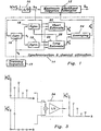
- FIGURE 1
- is a block diagram of an apparatus in accordance with the present invention;
- FIGURE 2
- is a flow chart illustrating the method in accordance with the present invention;
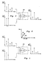
- FIGURE 3
- illustrates how channel estimates are combined in one embodiment of the present invention;
- FIGURE 4
- illustrates how channel estimates are combined in another embodiment in accordance with the present invention;
- FIGURE 5
- illustrates how channel estimates are combined in a further embodiment in accordance with the present invention; and
- FIGURE 6
- illustrates a simplified calculation of the amplitude of a complex number, which may be used in a preferred embodiment of the invention.
Thus,
In the illustrated embodiments two channel estimates have been combined. However, it is obvious that it is possible to combine more than two estimates. Thus, a feasible embodiment would be a combination of three channel estimates of different lengths. It is also appreciated that the present invention is applicable to other systems than the described GSM system.


Claims (15)
- A method of forming a channel estimate in a digital radio communication system, including the step of forming, from a received training sequence, a first burst synchronized channel estimate having a predetermined number of taps,
forming at least one further burst synchronized channel estimate; and
combining said first and said further channel estimates for forming a combined channel estimate
characterized in that said further channel estimate is formed from the same received training sequence and has fewer taps than the first channel estimate. - The method of claim 1, characterized by said combining step including averaging corresponding taps of said first and said further channel estimates, said further channel estimate(s) being padded with zero values in tap positions that correspond to taps of said first channel estimate that have no correspondence in said further channel estimate(s).
- The method of claim 2, characterized by considering only tap amplitude and disregarding tap phase of single tap further channel estimate(s) in said averaging.
- The method of claim 3, characterized by approximating the amplitude of each tap of said further channel estimate(s) with the sum of the amplitudes of its real and imaginary parts, respectively.
- The method of claim 2, 3 or 4, characterized by a single further channel estimate having a single tap.
- The method of claim 5, characterized by said single tap of said further channel estimate being averaged with a tap of maximum amplitude in said first channel estimate.
- The method of claim 5, characterized by averaging a tap of maximum amplitude of said first channel estimate with the single tap of said further channel estimate, estimating this single tap in the time position of the tap of maximum amplitude of the first channel estimate.
- The method of claim 2, 3, 4, 5, 6 or 7, characterized by weighted averaging of said first and said further channel estimates.
- An apparatus for forming a channel estimate in a digital radio communication system, including first means (20) for forming, from a received training sequence, a first burst synchronized channel estimate having a first predetermined number of taps,
second means (22) for forming at least one further burst synchronized channel estimate; and
means (24) for combining said first and said further channel estimate(s) for forming a combined channel estimate
characterized in that said second means (22) forms said further channel estimate from the same received training sequence and said further channel estimate has fewer taps than said first channel estimate. - The apparatus of claim 9, characterized by said combining means including averaging means (24) for averaging corresponding taps of said first and said further channel estimate(s), said further channel estimate(s) being padded with zero values in tap positions that correspond to taps of said first channel estimate that have no correspondence in said further channel estimate(s).
- The apparatus of claim 10, characterized by said averaging means (24) considering only tap amplitude and disregarding tap phase of single tap further channel estimate(s) in said averaging.
- The apparatus of claim 11, characterized by said averaging means (24) approximating the amplitude of each tap of said further channel estimate(s) with the sum of the amplitudes of its real and imaginary parts, respectively.
- The apparatus of claim 10, 11 or 12, characterized by a single further channel estimate having a single tap.
- The apparatus of claim 13, characterized by said first means (20) synchronizing said single tap of said further channel estimate with a tap of maximum amplitude in said first channel estimate.
- The apparatus of claim 13, characterized in that the means for forming the first channel estimate (20) is adapted to control the burst synchronization for the second channel estimate such that the single tap is estimated in the time position of the tap of maximum amplitude of the first channel estimate.
Applications Claiming Priority (3)
| Application Number | Priority Date | Filing Date | Title |
|---|---|---|---|
| SE9403724 | 1994-10-31 | ||
| SE9403724A SE503522C2 (en) | 1994-10-31 | 1994-10-31 | Channel estimation method and apparatus |
| PCT/SE1995/001275 WO1996013910A1 (en) | 1994-10-31 | 1995-10-27 | Method and apparatus for channel estimation |
Publications (2)
| Publication Number | Publication Date |
|---|---|
| EP0789955A1 EP0789955A1 (en) | 1997-08-20 |
| EP0789955B1 true EP0789955B1 (en) | 2002-07-17 |
Family
ID=20395799
Family Applications (1)
| Application Number | Title | Priority Date | Filing Date |
|---|---|---|---|
| EP95936824A Expired - Lifetime EP0789955B1 (en) | 1994-10-31 | 1995-10-27 | Method and apparatus for channel estimation |
Country Status (12)
| Country | Link |
|---|---|
| US (1) | US5903610A (en) |
| EP (1) | EP0789955B1 (en) |
| JP (1) | JP3636366B2 (en) |
| KR (1) | KR100256919B1 (en) |
| CN (1) | CN1092873C (en) |
| AU (1) | AU695989B2 (en) |
| CA (1) | CA2204135C (en) |
| DE (1) | DE69527436T2 (en) |
| FI (1) | FI114765B (en) |
| MX (1) | MX9703119A (en) |
| SE (1) | SE503522C2 (en) |
| WO (1) | WO1996013910A1 (en) |
Families Citing this family (45)
| Publication number | Priority date | Publication date | Assignee | Title |
|---|---|---|---|---|
| SE9601659D0 (en) * | 1996-04-30 | 1996-04-30 | Diabact Ab | Diagnostic drug preparation |
| AU688231B1 (en) * | 1997-03-12 | 1998-03-05 | Nokia Telecommunications Oy | Estimating CIR using correlation with line removal |
| JP3275779B2 (en) * | 1997-06-16 | 2002-04-22 | 日本電気株式会社 | Delay decision feedback type sequence estimation receiver |
| US6539050B1 (en) | 1997-06-26 | 2003-03-25 | Hughes Electronics Corporation | Method for transmitting wideband signals via a communication system adapted for narrow-band signal transmission |
| US6510147B1 (en) | 1997-07-15 | 2003-01-21 | Hughes Electronics Corporation | Method and apparatus for orthogonally overlaying variable chip rate spread spectrum signals |
| US6396822B1 (en) * | 1997-07-15 | 2002-05-28 | Hughes Electronics Corporation | Method and apparatus for encoding data for transmission in a communication system |
| US6084862A (en) * | 1997-09-26 | 2000-07-04 | Telefonaktiebolaget Lm Ericsson | Time dispersion measurement in radio communications systems |
| GB9810686D0 (en) * | 1998-05-19 | 1998-07-15 | King S College London | Dual direction estimator |
| GB2339120B (en) * | 1998-06-30 | 2003-03-19 | Nec Technologies | Channel estimation device for digital telecommunications stations |
| US6263030B1 (en) | 1998-07-01 | 2001-07-17 | Ericsson Inc. | Equalizer with channel tracker switching |
| US6373888B1 (en) | 1998-10-09 | 2002-04-16 | Telefonaktiebolaget Lm Ericsson (Publ) | Estimated channel with variable number of taps |
| EP0998054B1 (en) * | 1998-10-27 | 2002-01-23 | Robert Bosch Gmbh | Method for estimation of an impulse response of a signal transmission channel and mobile station |
| US6507602B1 (en) * | 1999-01-07 | 2003-01-14 | Ericsson, Inc. | Smoothing receiver channel estimates using spectral estimation |
| JP2000236284A (en) * | 1999-02-15 | 2000-08-29 | Sony Corp | Device and method for correlation detection |
| FR2790343B1 (en) * | 1999-02-26 | 2001-06-01 | Thomson Csf | SYSTEM FOR ESTIMATING THE COMPLEX GAIN OF A TRANSMISSION CHANNEL |
| US6614857B1 (en) * | 1999-04-23 | 2003-09-02 | Lucent Technologies Inc. | Iterative channel estimation and compensation based thereon |
| US6542560B1 (en) * | 1999-04-23 | 2003-04-01 | Lucent Technologies Inc. | Method of channel estimation and compensation based thereon |
| DE19920819C1 (en) | 1999-05-06 | 2000-10-26 | Bosch Gmbh Robert | Transmission channel estimation method for time discrete communication system, correcting original estimated pulse response by estimated additive noise |
| US6674815B2 (en) * | 1999-06-16 | 2004-01-06 | Ericsson, Inc | Method for symbol-spaced estimation and/or tracking of a fractionally-spaced fading radio channel |
| US6463107B1 (en) | 1999-07-01 | 2002-10-08 | Telefonaktiebolaget Lm Ericsson (Publ) | Methods and apparatuses for synchronization and modulation type detection |
| US6208842B1 (en) * | 1999-09-30 | 2001-03-27 | Motorola Inc. | Method and apparatus for estimating a channel parameter |
| US6628706B1 (en) | 1999-12-06 | 2003-09-30 | Telefonaktiebolaget Lm Ericsson (Publ) | Method and apparatus for transforming a channel estimate |
| EP1168739B1 (en) * | 2000-06-23 | 2005-10-19 | STMicroelectronics N.V. | Method and apparatus for estimating the impulse response of a transmission channel, in particular for a cellular mobile telephone |
| US6907092B1 (en) * | 2000-07-14 | 2005-06-14 | Comsys Communication & Signal Processing Ltd. | Method of channel order selection and channel estimation in a wireless communication system |
| US6970520B1 (en) | 2000-11-13 | 2005-11-29 | Telefonaktiebolaget Lm Ericsson (Publ) | Methods and systems for accumulating metrics generated by a sequence estimation algorithm |
| US20020172166A1 (en) * | 2001-03-22 | 2002-11-21 | Huseyin Arslan | Communications system and method for measuring short-term and long-term channel characteristics |
| US20020173286A1 (en) * | 2001-04-06 | 2002-11-21 | Bengt Lindoff | Radiocommunication employing selected synchronization technique |
| US7035353B2 (en) * | 2001-10-24 | 2006-04-25 | Zenith Electronics Corporation | Channel estimation method blending correlation and least-squares based approaches |
| SG108861A1 (en) * | 2002-07-18 | 2005-02-28 | Oki Techno Ct Singapore Pte | High rate receiver |
| FR2848361B1 (en) * | 2002-12-04 | 2005-02-18 | Nortel Networks Ltd | METHOD FOR DETECTING A SIGNAL AND RECEIVER SYSTEM FOR IMPLEMENTING THE METHOD |
| FR2848360B1 (en) * | 2002-12-04 | 2005-08-26 | Nortel Networks Ltd | METHOD FOR DETECTING A SIGNAL AND RECEIVER SYSTEM FOR IMPLEMENTING THE METHOD |
| US7065371B1 (en) * | 2003-02-20 | 2006-06-20 | Comsys Communication & Signal Processing Ltd. | Channel order selection and channel estimation in wireless communication system |
| US8149960B2 (en) * | 2003-05-23 | 2012-04-03 | Zenith Electronics Llc | Channel estimation for frequency selective multipath channels with long delay spreads based on an assumed physical channel |
| US7260055B2 (en) * | 2003-05-30 | 2007-08-21 | Agency For Science, Technology, And Research | Method for reducing channel estimation error in an OFDM system |
| DE10326283A1 (en) * | 2003-06-11 | 2005-01-13 | Siemens Ag | Method for determining channel coefficients of a data transmission channel |
| KR20050040615A (en) * | 2003-10-29 | 2005-05-03 | 삼성전자주식회사 | Apparatus for estimating channel using training sequence data for digital receiver and method thereof |
| US7995648B2 (en) * | 2004-04-09 | 2011-08-09 | Trident Microsystems (Far East) Ltd. | Advanced digital receiver |
| CA2560737A1 (en) | 2004-04-09 | 2005-10-27 | Micronas Semiconductors, Inc. | Apparatus for and method of controlling the operation of an equalizer |
| US7580454B2 (en) * | 2004-07-14 | 2009-08-25 | Fundacion Tarpuy | Multidimensional decision-directed trained adaptive equalization |
| WO2006020950A1 (en) * | 2004-08-12 | 2006-02-23 | Micronas Semiconductors, Inc. | Automatic gain control unit of a receiver |
| US7844232B2 (en) * | 2005-05-25 | 2010-11-30 | Research In Motion Limited | Joint space-time optimum filters (JSTOF) with at least one antenna, at least one channel, and joint filter weight and CIR estimation |
| US8107517B2 (en) * | 2005-12-09 | 2012-01-31 | Qualcomm Incorporated | Average-tap energy based thresholding for channel estimation in multi antenna systems |
| KR101531557B1 (en) * | 2008-10-20 | 2015-06-26 | 삼성전자주식회사 | Apparatus and method for channel estimation in mobile communication system |
| US8761274B2 (en) * | 2009-02-04 | 2014-06-24 | Acorn Technologies, Inc. | Least squares channel identification for OFDM systems |
| US9036722B2 (en) * | 2010-10-07 | 2015-05-19 | Centre Of Excellence In Wireless Technology | Robust channel estimation and interpolation |
Family Cites Families (13)
| Publication number | Priority date | Publication date | Assignee | Title |
|---|---|---|---|---|
| SE464902B (en) * | 1989-10-24 | 1991-06-24 | Ericsson Telefon Ab L M | PROCEDURE TO ADAPT A VITERBIAL ALGORITHM TO A CHANNEL WITH VARIOUS TRANSFER PROPERTIES AND A DEVICE IMPLEMENTING PROCEDURE |
| DE4001592A1 (en) * | 1989-10-25 | 1991-05-02 | Philips Patentverwaltung | RECEIVER FOR DIGITAL TRANSMISSION SYSTEM |
| SE465245B (en) * | 1989-12-22 | 1991-08-12 | Ericsson Telefon Ab L M | PROCEDURE TO PERFORM CHANNEL ESTIMATES FOR A FAITHFUL CHANNEL FOR TRANSFER OF SYMBOL SEQUENCES |
| US5251233A (en) * | 1990-12-20 | 1993-10-05 | Motorola, Inc. | Apparatus and method for equalizing a corrupted signal in a receiver |
| SE469052B (en) * | 1991-09-10 | 1993-05-03 | Ericsson Telefon Ab L M | PROCEDURE TO PICTURE A CHANNEL ESTIMATE FOR A TIME-ALIVE RADIO CHANNEL |
| JP2748743B2 (en) * | 1991-10-01 | 1998-05-13 | 日本電気株式会社 | Data receiving method |
| SE469678B (en) * | 1992-01-13 | 1993-08-16 | Ericsson Telefon Ab L M | SET FOR SYNCHRONIZATION AND CHANNEL TESTING IN TDMA RADIO SYSTEM |
| SE470371B (en) * | 1992-06-23 | 1994-01-31 | Ericsson Telefon Ab L M | Methods and apparatus for digital signal transmission to estimate transmitted symbols at a receiver |
| SE513422C2 (en) * | 1992-08-21 | 2000-09-11 | Ericsson Telefon Ab L M | Procedure for forming quality measures for signal bursts |
| FR2696604B1 (en) * | 1992-10-07 | 1994-11-04 | Alcatel Radiotelephone | Device for estimating a transmission channel. |
| US5581580A (en) * | 1993-05-20 | 1996-12-03 | Telefonaktiebolaget Lm Ericsson | Low complexity model based channel estimation algorithm for fading channels |
| SE513657C2 (en) * | 1993-06-24 | 2000-10-16 | Ericsson Telefon Ab L M | Method and apparatus for estimating transmitted symbols of a receiver in digital signal transmission |
| US5754599A (en) * | 1996-01-04 | 1998-05-19 | Motorola, Inc. | Method and apparatus for coherent channel estimation in a communication system |
-
1994
- 1994-10-31 SE SE9403724A patent/SE503522C2/en not_active IP Right Cessation
-
1995
- 1995-10-27 KR KR1019970702834A patent/KR100256919B1/en not_active IP Right Cessation
- 1995-10-27 AU AU38619/95A patent/AU695989B2/en not_active Ceased
- 1995-10-27 CA CA002204135A patent/CA2204135C/en not_active Expired - Fee Related
- 1995-10-27 WO PCT/SE1995/001275 patent/WO1996013910A1/en active IP Right Grant
- 1995-10-27 CN CN95196997.8A patent/CN1092873C/en not_active Expired - Fee Related
- 1995-10-27 JP JP51449996A patent/JP3636366B2/en not_active Expired - Lifetime
- 1995-10-27 EP EP95936824A patent/EP0789955B1/en not_active Expired - Lifetime
- 1995-10-27 US US08/836,056 patent/US5903610A/en not_active Expired - Lifetime
- 1995-10-27 DE DE69527436T patent/DE69527436T2/en not_active Expired - Lifetime
- 1995-10-27 MX MX9703119A patent/MX9703119A/en unknown
-
1997
- 1997-04-29 FI FI971827A patent/FI114765B/en active
Also Published As
| Publication number | Publication date |
|---|---|
| US5903610A (en) | 1999-05-11 |
| FI114765B (en) | 2004-12-15 |
| FI971827A0 (en) | 1997-04-29 |
| FI971827A (en) | 1997-06-26 |
| EP0789955A1 (en) | 1997-08-20 |
| DE69527436T2 (en) | 2003-01-16 |
| CA2204135C (en) | 2005-05-03 |
| KR100256919B1 (en) | 2000-05-15 |
| WO1996013910A1 (en) | 1996-05-09 |
| AU695989B2 (en) | 1998-08-27 |
| CA2204135A1 (en) | 1996-05-09 |
| SE9403724D0 (en) | 1994-10-31 |
| CN1171176A (en) | 1998-01-21 |
| SE9403724L (en) | 1996-05-01 |
| JP3636366B2 (en) | 2005-04-06 |
| AU3861995A (en) | 1996-05-23 |
| CN1092873C (en) | 2002-10-16 |
| JPH10508445A (en) | 1998-08-18 |
| SE503522C2 (en) | 1996-07-01 |
| DE69527436D1 (en) | 2002-08-22 |
| MX9703119A (en) | 1997-06-28 |
Similar Documents
| Publication | Publication Date | Title |
|---|---|---|
| EP0789955B1 (en) | Method and apparatus for channel estimation | |
| EP1110357B1 (en) | Methods and system for reducing co-channel interference using multiple sampling timings for a received signal | |
| US5353307A (en) | Automatic simulcast alignment | |
| JP4421682B2 (en) | Extended channel estimation equalizer for receivers in digital transmission systems. | |
| EP0784887B1 (en) | Signal detection in a tdma system | |
| Arslan et al. | Channel estimation in narrowband wireless communication systems | |
| US5251233A (en) | Apparatus and method for equalizing a corrupted signal in a receiver | |
| EP1232617B1 (en) | Method and receiver for whitening a signal disturbance in a communication signal | |
| MXPA97003119A (en) | Method and apparatus for calculation of ca | |
| JP4555403B2 (en) | Equalizer with State Reduction Sequence Estimation Method for Digital Transmission Equipment Receiver | |
| AU1115099A (en) | Method for joint equalization and detection of multiple user signals | |
| EP1016251B1 (en) | Method and arrangement for demodulating data symbols | |
| US7023935B2 (en) | Trellis based maximum likelihood signal estimation method and apparatus for blind joint channel estimation and signal detection | |
| Borah et al. | Receiver structures for time-varying frequency-selective fading channels | |
| JP2002101026A (en) | Receiver and adaptive equalization processing method | |
| EP1128617B1 (en) | Method and receiver for obtaining channel estimated values for equalising digital signals | |
| EP1128618A2 (en) | Method for tracking a time-variant channel impulse response | |
| WO2004100471A1 (en) | Method and apparatus for iterative estimation of channel- or filter-coefficients | |
| Lee et al. | The RSSE receiver with the channel estimator using the path history | |
| Kanno et al. | Blind equalization with generalized inverse channel estimation and fractional phase MLSE metrics for mobile communications |
Legal Events
| Date | Code | Title | Description |
|---|---|---|---|
| PUAI | Public reference made under article 153(3) epc to a published international application that has entered the european phase |
Free format text: ORIGINAL CODE: 0009012 |
|
| 17P | Request for examination filed |
Effective date: 19970417 |
|
| AK | Designated contracting states |
Kind code of ref document: A1 Designated state(s): DE FR GB |
|
| 17Q | First examination report despatched |
Effective date: 20010525 |
|
| GRAG | Despatch of communication of intention to grant |
Free format text: ORIGINAL CODE: EPIDOS AGRA |
|
| GRAG | Despatch of communication of intention to grant |
Free format text: ORIGINAL CODE: EPIDOS AGRA |
|
| GRAH | Despatch of communication of intention to grant a patent |
Free format text: ORIGINAL CODE: EPIDOS IGRA |
|
| GRAH | Despatch of communication of intention to grant a patent |
Free format text: ORIGINAL CODE: EPIDOS IGRA |
|
| GRAA | (expected) grant |
Free format text: ORIGINAL CODE: 0009210 |
|
| AK | Designated contracting states |
Kind code of ref document: B1 Designated state(s): DE FR GB |
|
| REG | Reference to a national code |
Ref country code: GB Ref legal event code: FG4D |
|
| REF | Corresponds to: |
Ref document number: 69527436 Country of ref document: DE Date of ref document: 20020822 |
|
| ET | Fr: translation filed | ||
| PLBE | No opposition filed within time limit |
Free format text: ORIGINAL CODE: 0009261 |
|
| STAA | Information on the status of an ep patent application or granted ep patent |
Free format text: STATUS: NO OPPOSITION FILED WITHIN TIME LIMIT |
|
| 26N | No opposition filed |
Effective date: 20030422 |
|
| PGFP | Annual fee paid to national office [announced via postgrant information from national office to epo] |
Ref country code: DE Payment date: 20121029 Year of fee payment: 18 Ref country code: FR Payment date: 20121107 Year of fee payment: 18 |
|
| PGFP | Annual fee paid to national office [announced via postgrant information from national office to epo] |
Ref country code: GB Payment date: 20121025 Year of fee payment: 18 |
|
| GBPC | Gb: european patent ceased through non-payment of renewal fee |
Effective date: 20131027 |
|
| REG | Reference to a national code |
Ref country code: DE Ref legal event code: R119 Ref document number: 69527436 Country of ref document: DE Effective date: 20140501 |
|
| PG25 | Lapsed in a contracting state [announced via postgrant information from national office to epo] |
Ref country code: GB Free format text: LAPSE BECAUSE OF NON-PAYMENT OF DUE FEES Effective date: 20131027 |
|
| REG | Reference to a national code |
Ref country code: FR Ref legal event code: ST Effective date: 20140630 |
|
| PG25 | Lapsed in a contracting state [announced via postgrant information from national office to epo] |
Ref country code: DE Free format text: LAPSE BECAUSE OF NON-PAYMENT OF DUE FEES Effective date: 20140501 Ref country code: FR Free format text: LAPSE BECAUSE OF NON-PAYMENT OF DUE FEES Effective date: 20131031 |