EP0788853B1 - Niederspannungs-Elektromagnetisches Nietwerkzeug - Google Patents
Niederspannungs-Elektromagnetisches Nietwerkzeug Download PDFInfo
- Publication number
- EP0788853B1 EP0788853B1 EP97200362A EP97200362A EP0788853B1 EP 0788853 B1 EP0788853 B1 EP 0788853B1 EP 97200362 A EP97200362 A EP 97200362A EP 97200362 A EP97200362 A EP 97200362A EP 0788853 B1 EP0788853 B1 EP 0788853B1
- Authority
- EP
- European Patent Office
- Prior art keywords
- voltage
- mass
- rivet
- driver
- capacitor banks
- Prior art date
- Legal status (The legal status is an assumption and is not a legal conclusion. Google has not performed a legal analysis and makes no representation as to the accuracy of the status listed.)
- Expired - Lifetime
Links
- 239000003990 capacitor Substances 0.000 claims description 160
- 230000035939 shock Effects 0.000 claims description 24
- 238000010304 firing Methods 0.000 claims description 20
- 239000006096 absorbing agent Substances 0.000 claims description 16
- 238000001514 detection method Methods 0.000 claims description 16
- 238000000034 method Methods 0.000 claims description 8
- 230000007246 mechanism Effects 0.000 claims description 6
- 239000007787 solid Substances 0.000 claims description 6
- 238000007667 floating Methods 0.000 claims description 4
- 238000007599 discharging Methods 0.000 claims description 3
- 230000000994 depressogenic effect Effects 0.000 description 22
- 238000012360 testing method Methods 0.000 description 12
- 239000010949 copper Substances 0.000 description 10
- 229910052802 copper Inorganic materials 0.000 description 10
- RYGMFSIKBFXOCR-UHFFFAOYSA-N Copper Chemical compound [Cu] RYGMFSIKBFXOCR-UHFFFAOYSA-N 0.000 description 9
- 238000000429 assembly Methods 0.000 description 8
- 238000010586 diagram Methods 0.000 description 8
- 239000000463 material Substances 0.000 description 8
- 101100365087 Arabidopsis thaliana SCRA gene Proteins 0.000 description 6
- 101000668165 Homo sapiens RNA-binding motif, single-stranded-interacting protein 1 Proteins 0.000 description 6
- 101000668170 Homo sapiens RNA-binding motif, single-stranded-interacting protein 2 Proteins 0.000 description 6
- 102100039692 RNA-binding motif, single-stranded-interacting protein 1 Human genes 0.000 description 6
- 102100039690 RNA-binding motif, single-stranded-interacting protein 2 Human genes 0.000 description 6
- 101150105073 SCR1 gene Proteins 0.000 description 6
- 101100134054 Saccharomyces cerevisiae (strain ATCC 204508 / S288c) NTG1 gene Proteins 0.000 description 6
- 238000009434 installation Methods 0.000 description 5
- 230000008569 process Effects 0.000 description 5
- 230000004044 response Effects 0.000 description 4
- 230000035945 sensitivity Effects 0.000 description 4
- 239000004593 Epoxy Substances 0.000 description 3
- XUIMIQQOPSSXEZ-UHFFFAOYSA-N Silicon Chemical compound [Si] XUIMIQQOPSSXEZ-UHFFFAOYSA-N 0.000 description 3
- XAGFODPZIPBFFR-UHFFFAOYSA-N aluminium Chemical compound [Al] XAGFODPZIPBFFR-UHFFFAOYSA-N 0.000 description 3
- 230000008859 change Effects 0.000 description 3
- 230000003993 interaction Effects 0.000 description 3
- 229910052710 silicon Inorganic materials 0.000 description 3
- 239000010703 silicon Substances 0.000 description 3
- 229910052782 aluminium Inorganic materials 0.000 description 2
- 230000008901 benefit Effects 0.000 description 2
- 230000015572 biosynthetic process Effects 0.000 description 2
- 238000005336 cracking Methods 0.000 description 2
- 230000003111 delayed effect Effects 0.000 description 2
- 238000009792 diffusion process Methods 0.000 description 2
- 239000002783 friction material Substances 0.000 description 2
- 230000006870 function Effects 0.000 description 2
- 238000004519 manufacturing process Methods 0.000 description 2
- 238000013024 troubleshooting Methods 0.000 description 2
- 229910000838 Al alloy Inorganic materials 0.000 description 1
- 229910001369 Brass Inorganic materials 0.000 description 1
- 239000004809 Teflon Substances 0.000 description 1
- 229920006362 Teflon® Polymers 0.000 description 1
- 229910001069 Ti alloy Inorganic materials 0.000 description 1
- 230000009471 action Effects 0.000 description 1
- 229910045601 alloy Inorganic materials 0.000 description 1
- 239000000956 alloy Substances 0.000 description 1
- 230000000712 assembly Effects 0.000 description 1
- 230000004888 barrier function Effects 0.000 description 1
- 230000000903 blocking effect Effects 0.000 description 1
- 239000010951 brass Substances 0.000 description 1
- 238000005253 cladding Methods 0.000 description 1
- 239000011248 coating agent Substances 0.000 description 1
- 238000000576 coating method Methods 0.000 description 1
- 239000004020 conductor Substances 0.000 description 1
- 150000001879 copper Chemical class 0.000 description 1
- 230000007423 decrease Effects 0.000 description 1
- 230000001419 dependent effect Effects 0.000 description 1
- 230000000881 depressing effect Effects 0.000 description 1
- 230000005672 electromagnetic field Effects 0.000 description 1
- 238000004146 energy storage Methods 0.000 description 1
- 230000002708 enhancing effect Effects 0.000 description 1
- 238000004880 explosion Methods 0.000 description 1
- 239000011152 fibreglass Substances 0.000 description 1
- 231100001261 hazardous Toxicity 0.000 description 1
- 229910052751 metal Inorganic materials 0.000 description 1
- 239000002184 metal Substances 0.000 description 1
- 238000000465 moulding Methods 0.000 description 1
- 238000005457 optimization Methods 0.000 description 1
- 230000009467 reduction Effects 0.000 description 1
- 239000011347 resin Substances 0.000 description 1
- 229920005989 resin Polymers 0.000 description 1
- 230000000452 restraining effect Effects 0.000 description 1
- 230000000630 rising effect Effects 0.000 description 1
- 238000003860 storage Methods 0.000 description 1
- 238000003466 welding Methods 0.000 description 1
- 238000004804 winding Methods 0.000 description 1
Images


Classifications
-
- B—PERFORMING OPERATIONS; TRANSPORTING
- B21—MECHANICAL METAL-WORKING WITHOUT ESSENTIALLY REMOVING MATERIAL; PUNCHING METAL
- B21J—FORGING; HAMMERING; PRESSING METAL; RIVETING; FORGE FURNACES
- B21J15/00—Riveting
- B21J15/10—Riveting machines
- B21J15/16—Drives for riveting machines; Transmission means therefor
- B21J15/24—Drives for riveting machines; Transmission means therefor operated by electro-magnets
-
- H—ELECTRICITY
- H02—GENERATION; CONVERSION OR DISTRIBUTION OF ELECTRIC POWER
- H02K—DYNAMO-ELECTRIC MACHINES
- H02K41/00—Propulsion systems in which a rigid body is moved along a path due to dynamo-electric interaction between the body and a magnetic field travelling along the path
- H02K41/02—Linear motors; Sectional motors
-
- Y—GENERAL TAGGING OF NEW TECHNOLOGICAL DEVELOPMENTS; GENERAL TAGGING OF CROSS-SECTIONAL TECHNOLOGIES SPANNING OVER SEVERAL SECTIONS OF THE IPC; TECHNICAL SUBJECTS COVERED BY FORMER USPC CROSS-REFERENCE ART COLLECTIONS [XRACs] AND DIGESTS
- Y10—TECHNICAL SUBJECTS COVERED BY FORMER USPC
- Y10T—TECHNICAL SUBJECTS COVERED BY FORMER US CLASSIFICATION
- Y10T29/00—Metal working
- Y10T29/53—Means to assemble or disassemble
- Y10T29/53004—Means to assemble or disassemble with means to regulate operation by use of templet, tape, card or other replaceable information supply
-
- Y—GENERAL TAGGING OF NEW TECHNOLOGICAL DEVELOPMENTS; GENERAL TAGGING OF CROSS-SECTIONAL TECHNOLOGIES SPANNING OVER SEVERAL SECTIONS OF THE IPC; TECHNICAL SUBJECTS COVERED BY FORMER USPC CROSS-REFERENCE ART COLLECTIONS [XRACs] AND DIGESTS
- Y10—TECHNICAL SUBJECTS COVERED BY FORMER USPC
- Y10T—TECHNICAL SUBJECTS COVERED BY FORMER US CLASSIFICATION
- Y10T29/00—Metal working
- Y10T29/53—Means to assemble or disassemble
- Y10T29/53709—Overedge assembling means
- Y10T29/5377—Riveter
- Y10T29/53774—Single header
Definitions
- This invention is directed to riveting apparatus and, more particularly, to low-voltage electromagnetic riveting apparatus.
- Rivets are widely used in aerospace structures to join parts together. They are used in the creation of sub-assemblies, such as the spar sub-assemblies used in aircraft wings, as well as to join the skin of an aircraft to structural sub-assemblies. Rivet material varies from relatively malleable aluminum to high-strength aluminum and titanium alloys. Rivets are created by passing a rivet blank through aligned holes in the parts to be joined and creating a head on at least one end of the rivet. That is, rivet blanks may have a preformed head on one end, or have no heads on either end prior to installation. In the case of a rivet with a preformed head, a head is only created on the non-headed end during installation.
- a rivet blank with a head on neither end has heads formed on both ends during installation.
- the formation of rivet heads during installation is commonly referred to as upsetting, since the head is formed by molding or upsetting the rivet material as the head is being formed.
- the present invention is directed to upsetting rivets that are non-headed at both ends prior to installation.
- Pneumatic vibrating gun and buckling bar machines have many disadvantages that make them unsuitable for use in the creation of critical aircraft structures, such as wingspar sub-assemblies.
- the major disadvantage of such machines is their inability to produce consistent quality joints having a high fatigue life.
- Another disadvantage is the substantial gun vibration noise produced by such machines.
- Such machines are generally incapable of upsetting large-sized aluminum rivets or high-strength alloy rivets.
- Hydraulic riveting machines have other disadvantages.
- One disadvantage is that opposing riveting forces are resisted through structural members that reach around the parts being joined.
- the structural members become massive as the size of the parts becomes large.
- an EMR is a riveter that uses electrical energy to produce the impact force needed to upset rivets.
- the force is developed by discharging the energy stored in a charge capacitor bank through a coil.
- an EMR includes two rivet guns positioned in contact with, and on opposite sides of, an unformed rivet.
- Each gun consists of a coil, a driver, and a recoil mass.
- the drivers are located between their respective coils and the related end of the rivet, in contact with the rivet, and the recoil mass is located on the side of the coils opposite the driver.
- EMR drivers are solid metal assemblies having a conductive plate in the form of a copper layer on the coil end of the assembly.
- a rivet die is located on the other end of the assembly, i.e., the end in contact with the rivet.
- the rivet die determines the shape of the rivet head.
- HVEMR high-voltage EMR
- the force produced by an HVEMR is of very short duration due to the rapid discharge of the capacitors. This results in the reaction force of the riveting process being stored momentarily in the kinetic energy of the recoil mass. More specifically, subsequent to a rivet upset pulse, the two rivet guns are each set into rearward motion away from the parts being assembled.
- the HVEMR guns are decelerated by the recoil mass and the restraining force created by the support structure. Recoilless operation is an essential feature of an HVEMR intended to be used on structures that cannot bear more than a fraction of the reaction force (65kNt) produced by such riveters.
- HVEMR current pulse rise time is usually less than 100 microseconds, the current pulse is exhausted in advance of appreciable deformation of the rivet. This leads to one of the major disadvantages of HVEMRs. Specifically, the interaction of the driver masses with the rivet results in an extremely high rate of deformation, which frequently causes cracks in the rivet heads.
- LVEMRs low-voltage electromagnetic riveters
- HVEMRs high-voltage electromagnetic riveters
- LVEMRs are similar in many ways to HVEMRs in the sense that they include two rivet guns that are in direct contact with and located on opposite sides of an unformed rivet.
- Each rivet gun consists of a coil, a driver, and a recoil mass.
- the major difference is that the capacitor bank voltage used with an LVEMR is 500 VDC or less.
- rivets are upset over a substantially longer period of time--one millisecond. The slower rise time is the result of a reduction in the natural electrical and mechanical frequency of the power supply, cable, coil, and driver system.
- LVEMRs as opposed to HVEMRs, substantially reduces rivet head cracking.
- HVEMRs HVEMRs
- LVEMRs of the type described in the '043 and '805 patents have advantages when compared to HVEMRs; they also have a number of disadvantages.
- LVEMRs of the type described in the '043 and '805 patents employ eddy currents to generate the repulsive force required to upset a rivet. More specifically, like HVEMRs described above, when a current pulse is applied to the coil of an LVEMR of the type described in the '043 and '805 patent, an eddy current is induced in a conductive driver plate. The interaction between the magnetic field created by the current flow through the coil and the magnetic field created by the eddy currents produces a net repulsive force.
- the finite conductivity of the driver plate limits efficiency by creating resistive power losses.
- the diffusion time of the magnetic field pulse through the copper driver plate limits maximum pulse duration.
- the efficiency of eddy current based LVEMRs is limited to a theoretical maximum of approximately 33%.
- LVEMR systems use a power pulse of less than 500 Volts DC, usually up to 450 Volts DC.
- the high-voltage portion of an LVEMR must remain electrically isolated during normal operation. This is usually accomplished by allowing the high-voltage portion of an LVEMR to float with respect to ground. However, if one point of a floating power supply becomes grounded, and another point is contacted by a grounded person, the person may receive a shock. Alternatively, if the other point is grounded via some element, a spark may occur, which could lead to equipment damage.
- Previously developed LVEMR use an electromechanically actuated circuit breaker to address this danger.
- This device sometimes called a shunt-trip breaker, is unsatisfactory for a variety of reasons. It is subject to mechanical wear, possibly resulting in mechanical failure. Electrical failure due to actuator coil burn-out is also possible. Response time and sensitivity are poor. In this regard, the total response time of such ground fault detectors incorporated in previously developed LVEMRs is on the order of 20 milliseconds from fault to shutdown. In this time, an LVEMR can attain hazardous voltages. Further, the sensitivity of such systems is in the 20 milliampere range, sufficient to deliver a painful shock through the hands of an average person.
- the charging systems of previously developed LVEMRs also have many limitations.
- the charging system commonly used in previously developed LVEMRs includes a voltage doubler circuit having both voltage stability and noise production problems.
- the voltage doubler output is fed to a capacitor bank through a TRIAC optocoupler.
- the common failure mode of a TRIAC optocoupler is full on. As a result, a runaway charge condition can occur if the TRIAC optocoupler fails. Such a possibility, of course, impacts the safe operation of a LVEMR.
- LVEMR controller includes Silicon Controlled Rectifier (SCR) triggering mounted on a large control circuit board that also includes other components.
- SCR Silicon Controlled Rectifier
- a LVEMR comprising two rivet guns including each a mass-mounted coil and a copper plate carrying the driver and being juxtaposed to the mass-mounted coil.
- Power is supplied to the system by a capacitor power supply, which provides a current pulse through the mass-mounted coil generating strong eddy currents in the copper plate. The magnetic field created thereby results in a repulsive force relative to the coil, and the driver affixed to the copper plate is propelled forward.
- LVEMR low-voltage electromagnetic riveter
- a low-voltage electromagnetic riveter (LVEMR) is provided.
- the LVEMR includes a programmable control system for controlling the charging and discharging of capacitor power supplies connected to two opposed rivet guns.
- Each of the rivet guns includes a mass-mounted coil, a driver, and a recoil mass.
- the driver of each gun includes a coil. The driver coils are juxtaposed against the mass-mounted coil.
- the mass-mounted coil and the driver coil of each gun are wound and connected to their related capacitor power supply such that when the power supply is discharged current flows through both coils so as to create a repulsive force that moves the driver away from the mass-mounted coil, against the end of a rivet to be upset.
- Both rivet guns are substantially simultaneously energized to create heads on both ends of a rivet. More specifically, the resulting repulsive magnetic force produced by each gun propels a rivet die against an aligned end of a rivet, upsetting the rivet.
- the capacitor power supplies are controllable. More specifically, the capacitor power supplies include a plurality of capacitors and a switching system for controlling the number of capacitors to be charged. As a result, the amount of power supplied to the rivet guns during discharge is controllable independent of the voltage setpoint, which is not the case with previously developed LVEMRs.
- the programmable control system includes a ground fault detection system that includes a solid state relay having low ground current sensitivity and rapid response time. When a grounded fault is detected, the solid state relay rapidly deactivates a power control relay that terminates the application of power to the LVEMR.
- the programmable control system includes a controllable delay generator that controls the discharging of the two capacitor power supplies such that one rivet gun is energized slightly before the other rivet gun.
- the shapes of the facing surfaces of the driver and mass-mounted coils are contoured to assist in maintaining alignment.
- the programmable control system includes a temperature transducer for sensing the temperature of the rivet guns and using the temperature information to control the operation of the capacitor power supplies in a manner that compensates for the change in coil resistivity that occurs with temperature changes.
- the programmable control system includes voltage transducers for sensing the voltage of the capacitor power supplies and using the sensed voltage information to prevent discharge of the power supplies if the voltage is below a predetermined rivet gun firing voltage.
- the programmable control system is modularized using off-the-shelf subsystems to the extent practicable in order to improve serviceability and reliability.
- the invention provides a new and improved LVEMR ideally suited for upsetting rivets during the assembly of various types of workpieces.
- Time-varying the rivet upset force provides better control of cracking, deformation flow lines, and radial interference.
- the inclusion of a controllable time delay generator substantially improves delay resolution while, at the same time, enhancing firing repeatability.
- the safety, reliability, and response time of a ground fault detection circuit that includes a solid state relay is significantly better than existing ground fault detection circuits that employ mechanical relays. Because the LVEMR programmable control system is modular and assembled from standard commercial parts, the cost and service problems associated with custom-designed controllers and sub-assemblies of previously developed LVEMRs are avoided.
- the modular design of the LVEMR programmable control system incorporates a commercial capacitor charging power supply with a Pulse Width Modulation switching configuration in order to provide finer charge resolution, easier troubleshooting, more noise-free operation and enhanced reliability.
- the inclusion of commercial power supplies also provides an increased level of safety since such power supplies include output transistors that shut down upon failure.
- FIGURE 1 is a block diagram of an embodiment of an LVEMR formed in accordance with this invention.
- the illustrated LVEMR includes right and left rivet guns 70 and 72; right and left capacitor power supplies 82 and 84 and a programmable control system 80. Also, illustrated are two workpieces 71 and 73 to be joined by a rivet 75 that is positioned in aligned holes in the workpiece.
- the programmable control system 80 receives information from a variety of sources including temperature transducers associated with the right and left rivet guns 70 and 72 and voltage transducers associated with the right and left capacitor power supplies 82 and 84 and a variety of pushbuttons, voltage control potentiometers, and safety checking mechanisms. Based upon the information it receives, the programmable control system 80 controls the operation of the right and left capacitor power supplies 82 and 84 which, in turn, control the operation of the right and left rivet guns 70 and 72.
- the rivet guns are positioned on each end of the rivet 75 shown as inserted into the two workpieces 71 and 73 to be joined together.
- Heads are formed when the rivet is upset by the rivet guns 70 and 72 applying suitable, substantially simultaneous, forces to the ends of the rivet.
- the programmable control system 80 includes a time delay that controls the application of power supplied by the right and left power supplies 82 and 84 to the right and left rivet guns 70 and 72 so that the rivet upset forces applied to the ends of the rivet are not exactly simultaneous. Rather, the time delay causes one rivet gun to apply an upset force to one end of the rivet slightly before the other rivet gun supplies an upset force to the other end of the rivet.
- each rivet gun includes mass-mounted and driver coils that simultaneously receive power from their respective capacitor power supplies. When energized, the mass-mounted and driver coils produce a net magnetic repulsive force that is used to upset the rivet.
- the right and left capacitor power supplies each include a switching system that allows a controllable configuration of capacitors to be changed.
- the programmable control system includes a ground fault detection system that minimizes the electrical shock hazard to personnel operating the LVEMR.
- the programmable control system 80 shown in FIGURE 1 comprises: right and left voltage setting potentiometers 26 and 28; a controller 30; a charge pushbutton switch 20; a dump pushbutton switch 22; a fire pushbutton switch 24; an emergency stop (E-stop) pushbutton switch 36; a start pushbutton switch 34; a safety loop 32; a start logic/E-stop circuit 38; right and left chargers 40 and 42; a delay generator 44; right and left SCR firing controllers 46 and 48; right and left ground fault detection circuits 52 and 53; right and left temperature transducers 56 and 57; and right and left voltage transducers 60 and 61.
- the outputs of the right and left chargers 40 and 42 are limited to a maximum output value, such as 450 volts, for example.
- the right and left capacitor power supplies 82 and 84 each include a capacitor bank 64 and 65 and an SCR circuit 68 and 69. As will be better understood from the following description, when enabled, the right and left SCR circuits 68 and 69 control the application of the charge stored in the right and left capacitor banks 64 and 65 to the right and left rivet guns 70 and 72, respectively.
- the controller 30 is, preferably, a programmable logic controller (PLC) that functions in the manner illustrated in FIGURES 14A-14C and described below. While various programmable logic controllers can be utilized, in one actual embodiment of the invention, the SLC 500 manufactured by the Allen Bradley Company, Milwaukee, Wisconsin, is used.
- PLC programmable logic controller
- the controller 30 receives a plurality of input signals and produces a plurality of output signals. More specifically, the charge, dump, and fire pushbutton switches 20, 22, and 24 are connected to the controller. When the pushbuttons of any of these switches are depressed, the depression is sensed by the controller, which causes suitable action to take place. For example, when the pushbutton of the charge pushbutton switch is depressed, the right and left capacitor banks 64 and 65 are charged in the manner described below. When the pushbutton of the dump pushbutton switch is depressed, the charge on the right and left capacitor bank is dumped, i.e., the capacitor banks are discharged. When the pushbutton of the fire pushbutton switch is depressed, the charge capacitor banks are discharged in a manner that causes the right and left rivet guns to upset a rivet.
- the right and left voltage-setting potentiometers 26 and 28 are also connected to the controller 30.
- the controller senses the setting of the right and left voltage-setting potentiometers and, in accordance therewith, controls the voltage magnitude of the charge stored in the right and left capacitor banks, respectively.
- the right and left temperature transducers 56 and 57 sense the temperature of the right and left rivet guns 70 and 72 and produce analog signals related thereto that are applied to the controller 30.
- the right and left voltage transducers 60 and 61 sense the voltage stored in the right and left capacitor banks 64 and 65 and produce related analog signals that are applied to the controller 30.
- the controller uses the temperature signals to compensate for resistance changes in the coils of the rivet guns and the voltage signals to determine when the capacitors are charged to the level set by the voltage-setting potentiometers, compensated for coil resistance changes.
- the controller 30 produces a plurality of command signals, some of which pass through the start logic/E-stop circuit 38.
- the start logic/E-stop circuit has the capability of interrupting the command signals in the manner described below. More specifically, the controller produces a left charge command, a right charge command, a fire command, and a dump command.
- the right and left charge commands are applied (through the start logic/E-stop circuit) to the right and left chargers 40 and 42, respectively, to cause the right and left chargers to supply a charge voltage to the right and left capacitor banks, respectively. While various types of chargers can be utilized, in one actual embodiment of the invention, the chosen charger was the model ALE #102-450-FL, manufactured by ALE Corporation, Neptune, New Jersey.
- the fire command signal produced by the controller is applied to the delay generator 44.
- the delay generator produces two output commands, one applied to the right SCR firing controller 46 and the other applied to the left SCR firing controller 48.
- the only difference between the commands produced by the delay generator is that one command is slightly delayed from the other output command.
- the chosen delay generator was the model CAL-AV#101AR with W1 and V0 options, manufactured by California Avionics, Campbell, California.
- the chosen SCR firing controllers were the model FCOREM60 manufactured by Enerpro, Goleta, California.
- the right and left SCR firing controllers produce fire commands that are applied to the right and left SCR circuits 68 and 69, respectively.
- the dump command signal produced by the controller 30 is applied to the right and left capacitor banks 64 and 65. As noted above, when a dump signal is produced, the charge on the right and left capacitor banks is dumped, i.e., the capacitor banks are discharged.
- each capacitor bank includes a switching system and a plurality of capacitors.
- the switching system selectively connects the capacitors to the right and left chargers.
- the capacitors connected to the chargers of course, charge. All of the charged capacitors are discharged simultaneously, either to the right and left rivet guns 70 and 72 when a fire command occurs, or to ground when a dump command occurs.
- the start logic/E-stop circuit 38 receives a plurality of inputs. More specifically, the start logic/E-stop circuit 38 is connected to the safety loop 32, the start pushbutton switch 34, and the E-stop pushbutton switch 36. In addition, the start logic/E-stop circuit is connected to the right and left ground fault detection circuits 52 and 53. Assuming that no ground faults exist and that the safety loop is completed, when the pushbutton of the start pushbutton switch is depressed, the start logic/E-stop circuit allows charge commands produced by the controller to enable the right and left chargers 40 and 42. If the pushbutton of the emergency stop pushbutton switch 38 is depressed, the start logic/E-stop circuit immediately disables the right and left chargers 40 and 42.
- an emergency stop signal is supplied to the controller 30 that causes the controller 30 to dump the charge on the right and left capacitor banks 64 and 65.
- the start logic/E-stop circuit immediately disables the right and left chargers 40 and 42 and causes the controller to dump the charge on the right and left capacitor banks 64 and 65.
- both the right and left capacitor banks 64 and 65 include a plurality of capacitors and a switching system that allows the capacitors to be selectively connected to the right and left chargers 40 and 42, respectively.
- the number of capacitors that can be charged is controllable.
- the power stored in the right and left capacitor banks is controllable. Since the amount of electric power stored in the right and left capacitor banks 64 and 65 is controllable, as well as the magnitude of the voltage of the stored power, the voltage magnitude of the power and amount of power applied to the right and left rivet guns 70 and 72 is independently controllable.
- FIGURE 2 is a schematic diagram illustrating one of the capacitor power supplies formed in accordance with the invention.
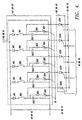
- FIGURE 4 is an alternative embodiment of a capacitor power supply formed in accordance with the invention.
- FIGURE 2 includes a capacitor bank 64 or 65 and an SCR circuit 68 or 69.
- the capacitor bank 64 or 65 comprises: a blocking diode designated Dblk; a dump resistor designated Rb; a dump contact designated Du; a main energy storage capacitor designated CX; four auxiliary capacitors designated C1, C2, C3, and C4; four capacitor cut-in switches designated S1, S2, S3, and S4; four capacitor cut-in relays designated K1, K2, K3, and K4; four isolating diodes designated D1, D2, D3, and D4; four internal resistances, designated R1, R2, R3 and R4; and four capacitor cut-in relay contacts designated K1a, K2a, K3a, and K4a.
- R1, R2, R3 and R4 represent the inherent wire and contact resistance of K1a, K2a, K3a and K4a.
- CX, C1, C2, C3, and C4 are standard design high-power electrolytic capacitors having a voltage capacity large enough to handle the maximum output voltage produced by the related charger 40 or 42, 450 volts in the example set forth above.
- the capacitor bank 64 or 65 is connected to the positive voltage output of the related charger 40 or 42 through Dblk.
- C1 is connected in series with K1a and R1 in that order.
- C2 is connected in series with K2a and R2 in that order.
- C3 is connected in series with K3a and R3 in that order.
- C4 is connected in series with K4a and R4 in that order.
- Each of these series connections, as well as CX, are connected in parallel.
- the other ends of R1, R2, R3 and R4 and one end of CX are connected to the cathode of Dblk.
- the anode of Dblk is connected to the high-voltage, e.g., positive, output of the related charger 40 or 42.
- the other ends of C1, C2, C3, C4 and CX are connected to the low-voltage, e.g., negative, output of the related charger 40 or 42.
- the outputs of the chargers are floating with respect to ground.
- K1a, K2a, K3a, and K4a and C1, C2, C3, and C4, respectively, are connected through D1, D2, D3, and D4, respectively, to the positive voltage side of CX.
- Rb is connected in series with Du and the series connection is connected in parallel with CX so that the one side of Du is connected to the positive voltage side of CX.
- Du are the contacts of a dump relay (not shown) operated by the controller 30 in the manner described below.
- S1 is connected in series with K1
- S2 is connected in series with K2
- S3 is connected in series with K3
- S4 is connected in series with K4.
- K1, K2, K3, and K4 control the status of K1a, K2a, K3a, and K4a, respectively. More specifically, when S1 is closed, K1 is energized and K1a is closed. Likewise, when S2, S3 and S4 are closed, K2a, K3a, and K4a are closed due to the energization of K2, K3, and K4. As a result, the state of S1, S2, S3, and S4 determine whether C1, C2, C3, or C4 are in or out of the capacitor bank circuit. Because the circuit capacitance of the capacitor banks is controllable, the power storage capability of the capacitor banks is controllable.
- capacitor bank circuit capacitance varies in a range from .0288 farads up to .0576 farads in steps of 7200 microfarads.
- the capacitance of each capacitor may be chosen differently to achieve other incremental values.
- additional or fewer auxiliary capacitors may be used.
- the capacitor banks 64 and 65 are enabled to be charged when Du is opened by the energization of a dump relay coil (not shown) operated by the controller 30. Energization of the dump relay opens normally closed contacts Du to prevent the discharge of electrical energy through Rb. Dblk is included to insure that current from the charger 40 or 42 flows into the capacitor bank 64 or 65. D1, D2, D3, and D4 serve to isolate C1, C2, C3, and C4, respectively, from CX.
- the SCR circuit 68 or 69 is shown as formed by a single high-power silicon controlled rectifier (i.e., a single SCR).
- a single SCR the positive output side of the capacitor bank 64 or 65 is connected to the anode of the SCR.
- the gate of the SCR is connected to the output of the related SCR firing controller 46 or 48, and the cathode of the SCR is connected to the mass-mounted and driver coils of the related rivet gun 70 or 72 in the manner described below.
- the input of the related voltage transducer 60 or 61 is connected across the output of the capacitor bank.
- the input of the related ground fault detection circuit 52 or 53 is connected to the positive voltage input of the capacitor bank.
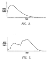
- FIGURE 3 illustrates the knee-shaped current pulse waveform generated by a capacitance bank of the type shown in FIGURE 2, and thus the force produced by a rivet gun energized by such a capacitor bank.
- the rivet upset force is relatively small.
- the upset force pulse exponentially rises to a peak value and then decreases exponentially to zero.
- FIGURE 4 illustrates an alternative embodiment of a capacitor bank 64' or 65' and SCR circuit 68' or 69' formed in accordance with the invention.
- a prime has been added to the reference numbers identifying the capacitor bank and the SCR circuit in order to distinguish FIGURE 4 from FIGURE 2.
- the capacitor bank 64' or 65' illustrated in FIGURE 4 comprises: five diodes designated Di1, Di2, Di3, Di4, and Di5; five switches designated Sw1, Sw2, Sw3, Sw4, and Sw5; five capacitors designated Ca1, Ca2, Ca3, Ca4, and Ca5; five dump resistors designated RD1, RD2, RD3, RD4, and RD5; and five dump contacts designated KD1, KD2, KD3, KD4, and KD5.
- the positive voltage output ofthe right charger 40 is connected to the anodes of Di1, Di2, Di3, Di4, and Di5.
- the cathodes of Di1, Di2, Di3, Di4, and Di5 are connected to Ca1, Ca2, Ca3, Ca4, and Ca5, respectively, through Sw1, Sw2, Sw3, Sw4, and Sw5, respectively.
- the open/closed states of Sw1, Sw2, Sw3, Sw4, or Sw5 determine if Ca1, Ca2, Ca3, Ca4, or Ca5 are or are not to be charged.
- the voltage magnitude of the charges on Ca1, Ca2, Ca3, Ca4, and Ca5 may be varied by opening Sw1, Sw2, Sw3, Sw4, and Sw5, respectively, during a charging cycle.
- open switch capacitors are charged to a relatively lower voltage at the end of a charging cycle.
- Other methods for accomplishing variable voltage charges on the capacitors may, of course, be used. For example, each capacitor could be charged by a separate voltage source or by a different voltage output of a common source.
- RD1 is connected in series with KD1; RD2 is connected in series with KD2; RD3 is connected in series with KD3; RD4 is connected in series with KD4; and RD5 is connected in series with KD5.
- the series connections are connected in parallel with Ca1, Ca2, Ca3, Ca4 and Ca5, respectively.
- KD1, KD2, KD3, KD4, and KD5 are normally closed.
- KD1, KD2, KD3, KD4, and KD5 are dump relay contacts that are operated by a dump relay coil (not shown) controlled by the controller 30. In the absence of a dump command, the dump relay is energized, opening KD1 through KD5. When a dump command occurs, the dump relay is deenergized, allowing KD1 through KD5 to close.
- the junctions between Sw1, Sw2, Sw3, Sw4, and Sw5 and Ca1, Ca2, Ca3, Ca4, and Ca5, respectively, are connected to the related SCR circuit 68' or 69'. More specifically, the SCR circuit comprises five high-power silicon controlled rectifiers designated SCR1, SCR2, SCR3, SCR4, and SCR5. The anodes of SCR1, SCR2, SCR3, SCR4, and SCR5 are connected to the junctions between Sw1, Sw2, Sw3, Sw4, and Sw5 and Ca1, Ca2, Ca3, Ca4, and Ca5, respectively, of the related capacitor bank 64' or 65'. The gates of SCR1, SCR2, SCR3, SCR4, and SCR5 are connected to the related SCR firing controller 46 or 48.
- the related SCR firing controller has five outputs that may include pulse transformer interfaces.
- the cathodes of SCR1, SCR2, SCR3, SCR4, and SCR5 are connected together and to both coils of the related rivet gun 70 or 72 in the manner described below.
- trigger pulses are sent to SCR1, SCR2, SCR3, SCR4, and SCR5 of the related SCR circuit 68' or 69' in a preprogrammed order.
- SCR1, SCR2, SCR3, SCR4, and SCR5 receive trigger pulses, they conduct current from Ca1, Ca2, Ca3, Ca4, and Ca5, respectively, to the rivet gun coils.
- the timing of the trigger pulses, as well as any voltage differences among Ca1, CA2, Ca3, Ca4, and Ca5, combine to create a variable current pulse.
- FIGURE 5 is an example of a multi-knee waveform representative of the type of variable current pulse, and thus the rivet upset force, that might be generated by a capacitor power supply of the type shown in FIGURE 4.
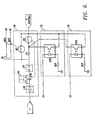
- FIGURE 6 illustrates a start logic/E-stop circuit 38 and right and left ground fault detection circuits 52 and 53 suitable for use in the LVEMR shown in FIGURE 1. Also shown in FIGURE 6 are the E-stop pushbutton switch 36; the start pushbutton switch 34; and the safety loop 32.
- the start logic/E-stop circuit includes: a resistor designated RS; a latch relay coil designated KS; normally open latch relay contacts designated KSa; a charger control relay coil designated KC and a pair of normally open charger control relay contacts designated KCa and KCb.
- the E-stop pushbutton switch 36 is normally closed, and the start pushbutton switch is normally open.
- E-stop pushbutton switch 36 is connected to one terminal of the start pushbutton 34 switch and the other terminal of the E-stop pushbutton switch is connected to the voltage source, V.
- KSa is connected in parallel with the terminals of the start pushbutton switch 34.
- the other terminal of the start pushbutton switch is connected to one side of the safety loop 32.
- the other side of the safety loop is connected through RS to one end of KS.
- the other end of KS is connected to the voltage return, i.e., to Vreturn.
- KC which controls the state of KCa and KCb, is connected in parallel with the series circuit formed by RS and KS.
- the state of KCa and KCb controls the enablement/disablement of the right and left chargers 40 and 42, respectively.
- the LVEMR is started by depressing the button of the start pushbutton switch 34. If the safety loop is closed and the E-stop pushbutton switch is closed, current flows through KS and KC. The energization of KS closes KSa, resulting in the flow of current through KS and KC being maintained. Energizing KC closes KCa and KCb, enabling the right and left chargers 40 and 42. As a result, the chargers are ready to charge the right and left capacitor banks 64 and 65, or 64' and 65'. As will be better understood from the following description of FIGURES 14A-14C, charging does not actually begin until the pushbutton of the charge pushbutton switch 20 is depressed.
- the voltage at the junction between the safety loop 32 and RS is fed back to the controller 30. If an emergency stop is required during the charging process, depression of the pushbutton of the E-stop pushbutton switch 36 ends the flow of current through KC and KS, thereby deenergizing KC and KS. As a result, KSa will open, maintaining current flow stopped after the button of the E-stop pushbutton switch is released. Deenergization ofKC opens KCa and KCb, disabling the right and left chargers.
- the drop in voltage at the junction between the safety loop 32 and RS causes the controller 30 to issue a dump command that discharges the right and left capacitor banks.
- the ground fault detection circuits 52 and 53 each comprise: a solid state relay in the form of an electro-optical coupler designated SSR; and a resistor designated RGF.
- the sensitivity of the SSR is five milliamperes.
- the SSR includes a photodiode and an optically activated transistor.
- the anode of the photodiode of the SSR is connected to the positive side of the related capacitor bank 64 or 65 as shown in FIGURES 2 and 4.
- the cathode of the photodiode is connected to ground.
- the collectors of the phototransistors of the SSRs are connected to the junction between RS and KS of the start logic/E-stop circuit 38.
- the emitters of the phototransistors of the SSRs are connected to the Vretum side of KC and KS.
- the phototransistors of the SSRs both bridge KS.
- ground fault circuit resistors RGF can have various values, in one actual embodiment of the invention 15.5 kiloohms was chosen. Obviously, other values may be chosen as long as the chosen value allows the SSR to respond with sufficient speed and SSR input power is not exceeded.
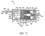
- FIGURE 7 is a top plan view, partially in section, of one of the rivet guns 70, 72.
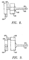
- FIGURES 8 and 9 are simplified top and side views showing the major elements of the rivet gun; namely, a driver 125, a driver coil 131, and a mass-mounted coil 135.
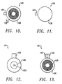
- FIGURES 10 and 11 are front and rear views, respectively, of the mass-mounted coil 135 and
- FIGURES 12 and 13 are front and rear views, respectively, of the driver coil 131.
- the rivet gun illustrated in FIGURE 7 includes: a housing 129; a rivet die 121; a driver rod bushing 123; a coil spring 127; a recoil mass 139; a pneumatic shock absorber 140; a pair of flexible cables 141; a pneumatic valve 157; and a driver coil guide bushing 161.
- the housing 129 provides mechanical support for the other components of the rivet gun as well as a barrier that prevents the entry of unwanted foreign material. All of the components, except for the rivet die 121, the driver rod bushing 123, and the pneumatic valve 157, are mounted in the housing.
- the driver rod bushing is mounted on the outer surface of one of the walls of the housing 129.
- the driver 125 includes a conical base 124 and a rod 126 that is integral with and protrudes longitudinally outwardly from the tip of the conical base. The outer end of the rod passes through the driver rod bushing 123.
- the rivet die 121 is mounted on the outer tip of the rod 126 of the driver 125.
- the rivet die 121 may be attached to the rod 126 in any suitable manner.
- the rivet die 121 may be attached to the rod 126 by screwing the die onto the end of the driver rod or by a snap fit mechanism.
- the driver coil 131 Affixed to the conical base 124 of the driver 125, opposite the rod 126, is the driver coil 131. Located on the opposite side of the driver coil 131 from the driver 125 is the mass-mounted coil 135. As shown in FIGURES 10-13, the driver and mass-mounted coils 131 and 135 are generally cylindrical in shape.
- the driver coil guide bushing 161 is located on the inner wall of the housing 129 and is positioned so as to surround the driver coil 131 and, preferably, the mass-mounted coil 135.
- the driver coil guide bushing 161 extends outwardly from the driver coil 131 to the wall of the housing that supports the driver rod bushing 123.
- the driver coil guide bushing 161 includes a shoulder 162 where the bushing meets the wall of the housing that supports the driver coil bushing 123.
- the shoulder surrounds the rod 126 of the driver 125.
- the coil spring 127 surrounds the rod 126 of the driver 125, and lies between the conical base 124 of the driver 125 and the wall of the housing 129 that supports the driver rod bushing 123.
- the recoil mass 139 is affixed to the side of the mass-mounted coil 135 remote from the side of the mass-mounted coil that faces the driver coil 131.
- the recoil mass 139 is formed of a plurality of plates, some of which can be removed to allow the magnitude of the recoil mass to be adjusted.
- the pneumatic shock absorber 140 includes a cylinder 143 and a rod 145 connected to a piston (not shown) located in the cylinder 143.
- the pneumatic shock absorber 140 is mounted in the housing 129 such that the outer end of the rod 145 extends toward the recoil mass 139 and the remote end of the cylinder 143 impinges on and is attached to the wall of the housing 129 opposite the wall that supports the driver rod bushing 123.
- the rod 145 and the cylinder 143 of the pneumatic shock absorber 140 are longitudinally aligned with the longitudinal axis of the rod 126 of the driver 125.
- a plurality of pneumatic shock absorbers can be used in place of the single pneumatic shock absorber shown in FIGURE 7 in which case the longitudinal axes of the rods and cylinders of the pneumatic shock absorbers will lie parallel to one another and parallel to the longitudinal axis of the rod 126 of the driver 125.
- Inlets/outlet ports 146 and 148 are located at opposite ends of the cylinder 143 of the pneumatic shock absorber 140. Conduits 147 and 149 couple the shock absorber ports 146 and 148 to the pneumatic valve 157.
- the pneumatic valve 157 is also connected to a pressurized air line 163. As a result of this arrangement, the position of the valve 157 can be used to control the extension and retraction of the rod 145 of the shock absorber 140.
- the pneumatic valve which includes a pressure relief valve, can be used to control the amount of force applied by the pneumatic shock absorber to the recoil mass 139 and, thus, to the mass-mounted coil 135.
- the driver coil guide bushing 161, including the shoulder 162, is formed of a low-friction material, preferably Teflon. While the driver rod guide bushing 123 is also formed of a low-friction material, a harder material, such as brass, is preferred.
- the driver rod bushing 123 and the driver coil guide bushing 161 allow the driver 125 to slide back and forth.
- the coil spring 127 forms a retraction spring that presses the driver coil 131 against the mass-mounted coil 135 prior to energization of the driver and mass-mounted coils in the manner described herein.
- FIGURES 10 and 11 are front and rear views, respectively, of the mass-mounted coil 135, and FIGURES 12 and 13 are front and rear views of the driver coil 131.
- Both coils are wound of flat copper conductors 136 embedded in an epoxy 138.
- the coils are exposed (except for a thin coating that prevents shorting) on their facing surfaces.
- the front face (FIGURE 10) of the mass-mounted coil 135 is exposed as is the rear face (FIGURE 13) of the driver coil 131.
- the other faces are enclosed by the epoxy, as seen in FIGURES 11 and 12. While the facing surfaces of the coils may be flat, preferably one surface is slightly concave and the other is slightly convex in a corresponding manner to assist in coil alignment.
- a block 133 preferably formed of the same material in which the coil is embedded, i.e., fiberglass epoxy reinforced resin, is located on one edge of the driver coil 131.
- the terminals 137 of the moving coil 131 extend outwardly from the block 133, in the direction of the mass-mounted coil 135, on one side thereof, as shown in FIGURE 9.
- one end of the pair of flexible cables 141 is connected to the terminals 137 of the driver coil 131.
- the path of the flexible cables 141 defines a relatively large loop and the other end of the flexible cables exit the housing 129 via a slot 142 formed in the side of the housing. More specifically, the slot 142 is aligned with the recoil mass 139 and the mass-mounted coil 135.
- the recoil mass 139 provides support for the cables 141 in the region of the slot 142.
- the flexible cables may take on a variety of forms, the presently preferred flexible cable material is known as welding cable. Because the terminals 137 of the driver coil 131 lie parallel to the direction of movement of the driver coil 133, the connection between the terminals 137 and the flexible cables 141 is in the direction of minimum strain.
- the terminals 154 of the mass-mounted coil 135 extend outwardly through the slot 142 in the housing 129.
- Wires 153 and 155 connect the ends of the flexible cables 141 and the terminals 154 of the mass-mounted coil 135 to the related firing control SCR 68 or 69. More specifically, one wire of each coil is connected to the negative side of the related capacitor bank and the other wire is connected to the cathode of the related SCR circuit 68 and 69 or 68' and 69'.
- a strain relief 151 provides support for the wires where they exit the slot 142.
- the repulsive magnetic force causes the driver coil 131 to rapidly move away from the mass-mounted coil 135.
- the rivet die 121 of the rivet guns apply an upset force to the related ends of a rivet located between the rivet guns. See FIGURE 1. The resulting upset force upsets the rivet, forming heads on both ends of the rivet.
- the shock of the resulting impact is absorbed by the recoil mass 139 and the pneumatic shock absorber 140. More specifically, the recoil force causes the rod 145 of the pneumatic shock absorber to move into the cylinder 143 against the pressure stored in the cylinder on the side of the shock absorber piston remote from the rod 145.
- the pressure increase is relieved by the pressure release valve incorporated into the pneumatic valve 157.
- the shock absorber dampens the recoil shock produced by the actuation of the rivet gun.
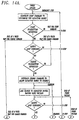
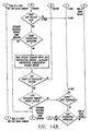
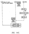
- FIGURES 14A through 14C form a flow diagram illustrating the overall sequence of operation of the LVEMR illustrated in FIGURE 1 and described above.
- the controller 30 produces a dump command (step 1) that causes the capacitor banks to be discharged by holding the dump relay deenergized, which causes the Du contacts (FIGURE 2) or the KD1-KD5 contacts (FIGURE 4) to remain closed.
- the right and left voltage-setting potentiometers 26 and 28 are set to the desired capacitor bank voltage levels.
- the capacitance control switches for each capacitor bank 64 (S1-S4, FIGURE 2, or SW1-SW5, FIGURE 4) are set to their desired position.
- Step 2 a test is made to determine if the pushbutton of the start pushbutton switch 34 has been depressed. If the start pushbutton has not been depressed, the program cycles back to Step 1. The program remains in this loop until the start pushbutton is depressed. As a result, the capacitor banks are maintained discharged.
- Step 3 a test is made to determine if the safety loop 32, as shown in FIGURE 6, is unbroken. The safety loop 32 is closed as long as safe operation of the LVEMR is maintained. This test is accomplished by determining if a voltage is present at the junction between the safety loop 32 and RS (FIGURE 6). If no voltage is present, which means that the safety loop is broken, the program cycles to Step 1.
- Step 4 determines if the pushbutton of the charge pushbutton switch 20 has been depressed. If the charge pushbutton has not been depressed, the program cycles to Step 3. The program remains in this loop until the charge pushbutton is depressed.
- the controller produces a charge command that energizes the dump relay, which causes the Du contacts (FIGURE 2) or the KD1-KD5 contacts (FIGURE 4) to open.
- the right and left chargers 40 and 42 are enabled, which enables the charging of the right and left capacitor banks 64 and 65 or 64' and 65'. As a result, as shown at Step 6, the capacitor banks begin to charge.
- Step 7 a test is made to determine if the safety loop 32 is unbroken. As noted above, the state of the safety loop is determined by testing the voltage at the junction between the safety loop 32 and RS (FIGURE 6). If the safety loop is broken, the program cycles to Step 1 and the capacitor bank charges are dumped, i.e., the capacitor banks are discharged.
- Step 8 the capacitor banks 64 and 65 or 64' and 65' continue charging and the program cycles to Step 8.
- the outputs of the temperature transducers 56 and 57 and the voltage transducers 60 and 61 are tested to determine if they are below safe levels. If the output of any of the transducers is above a safe level, the program cycles to Step 1 and the capacitor banks are discharged. If the outputs of all of the transducers are below safe levels, the capacitor banks continue to charge and the program cycles to Step 9.
- Step 9 a test is made to determine if the pushbutton of the dump pushbutton switch 22 has been depressed. If the dump pushbutton has been depressed, the program cycles to Step 16, which is described below.
- Step 10 the outputs of the temperature transducers 56 and 57 are read and the readings used to calculate temperature compensation voltage offsets. More specifically, as well known to those skilled in the art, the resistance of copper increases with temperature. As a result, as temperature increases, an increased voltage is required to cause a specific amount of current to flow through a copper element, such as the coils of the rivet guns 70 and 72. Since a specific amount of rivet gun coil current is required to produce a specific amount of rivet upset force, in order to compensate for the change in coil resistance that occurs with temperature changes, the program calculates the voltage change for each rivet gun necessary to compensate for the changed resistance. The voltage compensation value is summed with the desired voltage value to produce a compensated voltage value that is adequate to produce the desired force.
- Step 11 a test is made to determine if the capacitor banks have attained the compensated voltage values determined in Step 10. If the capacitor banks have not attained the compensated voltage values, the program cycles to Step 6 and charging continues. The program remains in this loop until both capacitor banks reach their compensated voltage values.
- Step 12 a test is made to determine if an automatic discharge timeout period has elapsed. This test is included to prevent the capacitor banks from storing a charge for an excessive period of time. If the timeout period elapses before a fire command is received, the program cycles to Step 16, described below, whereat the capacitor banks are discharged.
- Step 13 a test is made to determine if the safety loop 32 is unbroken.. If the safety loop 32 is broken, the program cycles to Step 1. If the safety loop 32 is not broken, a test is made (Step 14) to determine if the pushbutton of the fire pushbutton switch 24 has been depressed. If the fire pushbutton has not been depressed, the program cycles to Step 7. The program remains in this loop until the fire pushbutton is depressed or one of the heretofore-described conditions that causes the program to exit the loop occur. When the fire pushbutton is depressed, the program delay generator is enabled, causing the program to cycle to Step 15 (FIGURE 14C). Step 15 includes three substeps. The first substep is the firing of one of the rivet guns. The second substep is the firing delay created by the delay generator and the third substep is the firing of the second rivet gun. The firing delay is adjustable, preferably anywhere between 0 and 1000 microseconds.
- Step 16 After the rivet guns fire, the program cycles to Step 16. At step 16, a dump command is generated, causing both capacitor banks to be discharged. Thereafter, the program cycles to Step 3 and Steps 3-16 are repeated.
- an LVEMR formed in accordance with the invention can be remotely controlled by a host robot or computer.
- the functions performed by the right and left voltage setting potentiometers 26 and 28, the charge, dump and fire pushbuttons 20, 22 and 24, and the safety loop 32 would be controlled by robot or computer-generated signals.
- the delay provided by the delay generator 44 could also be remotely controlled.
- the status data provided by the voltage and temperature transducers and other devices could be provided to the robot or computer, as desired.
- recoil mechanisms other than the ones depicted in FIGURE 7 can be employed in actual embodiments of the invention.
- the shell-type recoil mechanism employed in some LVEMRs manufactured by Electroimpact, Inc., Mukilteo, Washington, can be used, if desired.
- the invention can be practiced otherwise than as specifically described herein.
Landscapes
- Engineering & Computer Science (AREA)
- Power Engineering (AREA)
- Physics & Mathematics (AREA)
- Chemical & Material Sciences (AREA)
- Combustion & Propulsion (AREA)
- Electromagnetism (AREA)
- Mechanical Engineering (AREA)
- Relay Circuits (AREA)
- Fuses (AREA)
- Arc Welding Control (AREA)
- Protection Of Static Devices (AREA)
- Charge And Discharge Circuits For Batteries Or The Like (AREA)
- Portable Nailing Machines And Staplers (AREA)
Claims (17)
- Elektromagnetischer Niederspannungsnieter zum Anstauchen von Nieten (75), umfassend:(a) zwei Nietkanonen (70, 72), die auf entgegengesetzten Enden eines anzustauchenden Niets positionierbar sind, wobei jede der Nietkanonen folgendes umfasst:(i) eine massemontierte Spule (135);(ii) eine Treiberspule (131), die gegen die massemontierte Spule angrenzt und in einem Kreis bzw. einer Schaltung mit der massemontierten Spule verbunden ist, wobei die massemontierte Spule und die Treiberspule derart gewickelt sind, dass ein Stromfluss durch die massemontierte Spule und die Treiberspule eine elektromagnetische Abstoßungskraft zwischen den Spulen erzeugt;(iii) einen an der Treiberspule auf der gegenüber der massemontierten Spule entgegengesetzten Seite derselben befestigten und mit einem Ende eines anzustauchenden Niets in Abfluchtung befindlichen Treiber (125); und(b) eine mit der massemontierten Spule und der Treiberspule der Nietkanonen verbundene Kondensatorstromversorgung (82, 84) zum Speichern von elektrischer Energie und zum selektiven Entladen von elektrischem Strom in die massemontierte Spule und die Treiberspule der Nietkanonen; und(c) ein programmierbares Steuer- bzw. Regelsystem (80), das mit der Kondensatorstromversorgung zum Laden der Kondensatorstromversorgung und zum Bewirken, dass die Kondensatorstromversorgung selektiv elektrischen Strom in die massemontierte Spule und die Treiberspule der Nietkanonen (70, 72) entlädt, verbunden ist.
- Elektromagnetischer Niederspannungsnieter, wie im Anspruch 1 beansprucht, worin die Kondensatorstromversorgung eine erste und zweite Kondensatorbank (64, 65) umfasst, wobei eine der Kondensatorbänke der massemontierten Spule (135) und der Treiberspule (131) von einer der Nietkanonen (70, 72) verbunden ist, und die andere der Kondensatorbänke mit der massemontierten Spule und der Treiberspule der anderen der Nietkanonen verbunden ist, wobei jede der Kondensatorbänke (64, 65) eine Mehrzahl von Kondensatoren umfasst, sowie ein Schaltsystem zum selektiven Verbinden der Kondensatoren mit dem programmierbaren Steuer- bzw. Regelsystem für das selektive Laden durch das programmierbare Steuer- bzw. Regelsystem.
- Elektromagnetischer Niederspannungsnieter, wie im Anspruch 2 beansprucht, worin die erste und zweite Kondensatorbank (64, 65) erdfrei sind und worin das programmierbare Steuer- bzw. Regelsystem eine erste und zweite Erddetektionsschaltung umfasst, wobei eine der Erddetektionsschaltungen mit jeder aus der ersten und zweiten Kondensatorbank zum Detektieren der Erdung der Kondensatorbänke verbunden ist.
- Elektromagnetischer Niederspannungsnieter, wie im Anspruch 2 oder 3 beansprucht, worin die programmierbare Steuer- bzw. Regeleinrichtung (80) folgendes umfasst:einen Startschalter (34);einen Notstopp (E-Stopp)-Schalter (36); undeine Startlogik-/E-Stopp-Schaltung (38), wobei der Startschalter, der E-Stopp-Schalter und die Massefehlerdetektionsschaltungen (52, 53) im Kreis bzw. in einer Schaltung mit der Startlogik-/E-Stopp-Schaltung (38) derart verbunden sind, dass die erste und zweite Kondensatorbank durch das programmierbare Steuer- bzw. Regelsystem (80) geladen werden kann, wenn der Startschalter (34) geschlossen wird bzw. ist, wenn der Notstoppschalter (36) geschlossen wird bzw. ist, und die Erdungsfehlerdetektionsschaltungen keinen Erdungsfehler auf jeder aus der ersten oder zweiten Kondensatorbank detektieren.
- Elektromagnetischer Niederspannungsnieter, wie im Anspruch 4 beansprucht, worin die Erdungsfehlerdetektionsschaltungen ein Festkörper- bzw. Solid-State-Relais umfassen, das aktiviert wird, wenn ein Erdungsfehler auf der Kondensatorbank auftritt, mit welcher der Erdungsfehlerdetektor verbunden ist.
- Elektromagnetischer Niederspannungsnieter, wie im Anspruch 4 oder 5 beansprucht, worin das programmierbare Steuer- bzw. Regelsystem außerdem eine im Kreis bzw. in einer Schaltung mit dem Startschalter verbundene Sicherheitsschleife umfasst, wobei der E-Stopp-Schalter und die Startlogik-/E-Stopp-Schaltung derart sind, dass das programmierbare Steuerbzw. Regelsystem daran gehindert wird, eine Ladung auf die erste und zweite Kondensatorbank aufzubringen, wenn die Sicherheitsschleife offen ist.
- Elektromagnetischer Niederspannungsnieter, wie in irgendeinem der Ansprüche 2 bis 6 beansprucht, worin die Kondensatorstromversorgung außerdem eine erste und zweite Entladungssteuer- bzw. -regelschaltung umfasst, von denen jede mit einer aus der ersten und zweiten Kondensatorbank verbunden ist und worin das programmierbare Steuer- bzw. Regelsystem einen Verzögerungsgenerator zum Steuern bzw. Regeln des Anlegens von Entladungssteuer- bzw. Regelsignalen an die erste und zweite Entladungssteuer- bzw. -regelschaltuhg umfasst.
- Elektromagnetischer Niederspannungsnieter, wie im Anspruch 7 oder 8 beansprucht, worin das programmierbare Steuer- bzw. Regelsystem außerdem eine erste und zweite Auslösungssteuer- bzw. -regeleinrichtung (46, 48) umfasst, die jeweils zwischen den Verzögerungsgenerator (44) und die erste und zweite Entladungssteuer- bzw. -regelschaltung geschaltet ist.
- Elektromagnetischer Niederspannungsnieter, wie in irgendeinem der Ansprüche 2 bis 8 beansprucht, worin das programmierbare Steuer- bzw. Regelsystem außerdem folgendes umfasst:ein erstes und zweites Spannungseinstellpotentiometer (26, 28);einen Ladeschalter (20);einen Auslösungsschalter (24);eine erste und zweite Ladung bzw. Ladeeinrichtung, die jeweils mit der ersten und zweiten Kondensatorbank zum Laden der ersten und zweiten Kondensatorbank (64, 65) verbunden sind; undeine mit dem ersten und zweiten Spannungseinstellpotentiometer (26, 28), dem Ladeschalter, dem Auslösungsschalter und der ersten und zweiten Ladeeinrichtung verbundene Steuerbzw. Regeleinrichtung zum Bewirken, dass die erste und zweite Ladeeinrichtung eine Ladung zu der ersten und zweiten Kondensatorbank (64, 65) zuführen, die bewirkt, dass sich die erste und zweite Kondensatorbank bis zu dem Spannungsniveau aufladen, welches durch das erste bzw. zweite Spannungseinstellpotentiometer eingestellt ist, wenn der Ladeschalter geschlossen wird, und zum Bewirken, dass der Verzögerungsgenerator (44) die erste und zweite Auslösesteuer- bzw. -regeleinrichtung (46, 48) befähigt, zu bewirken, dass die erste und zweite Kondensatorbank (64, 65) elektrischen Strom in die Treiberspule und die massemontierte Spule der ersten und zweiten Nietkanone (70, 72) entladen, wenn der Auslöseschalter geschlossen wird.
- Elektromagnetischer Niederspannungsnieter, wie im Anspruch 9 beansprucht, worin das programmierbare Steuer- bzw. Regelsystem einen ersten und zweiten, mit der ersten und zweiten Kondensatorbank (64, 65) verbundenen Spannungsumsetzer (60, 61) zum Abfühlen der Spannung auf der ersten und zweiten Kondensatorbank und zum Zuführen eines Spannungsgrößensignals zu der Steuer- bzw. Regeleinrichtung umfasst.
- Elektromagnetischer Niederspannungsnieter, wie im Anspruch 10 beansprucht, worin das programmierbare Steuer- bzw. Regelsystem außerdem einen mit der ersten und zweiten Nietkanone (70, 72) verbundenen ersten und zweiten Temperaturumsetzer (56, 57) zum Abfühlen der Temperatur der ersten und zweiten Nietkanone (70, 72) und zum Zuführen eines Temperatursignals zu der Steuer- bzw. Regeleinrichtung umfasst, und worin die Steuer- bzw. Regeleinrichtung das Ladungsniveau der ersten und zweiten Kondensatorbank teilweise basierend auf den Temperatursteuer- bzw. -regelsignalen, die durch den ersten und zweiten Temperaturumsetzer erzeugt worden sind, steuert bzw. regelt.
- Elektromagnetischer Niederspannungsnieter, wie im Anspruch 9, 10 oder 11 beansprucht, worin die programmierbaren Steuer- bzw. Regelsysteme außerdem einen mit der ersten und zweiten Nietkanone (70, 72) verbundenen ersten und zweiten Temperaturumsetzer (56, 57) zum Abfühlen der Temperaturumsetzer umfasst, die mit der ersten und zweiten Nietkanone zum Abfühlen der Temperatur der ersten und zweiten Nietkanone und zum Zuführen eines Temperatursignals zu der Steuer- bzw. Regeleinrichtung verbunden sind, umfasst; und worin die Steuerbzw. Regeleinrichtung das Ladungsniveau der ersten und zweiten Kondensatorbank teilweise basierend auf den Temperatursteuer- bzw. -regelsignalen, die durch den ersten und zweiten Temperaturumsetzer erzeugt worden sind, steuert bzw. regelt.
- Elektromagnetischer Niederspannungsnieter, wie in irgendeinem der Ansprüche 2-12 beansprucht, worin:wobei das programmierbare Steuer- bzw. Regelsystem (80) einen Umspeicherungsschalter (22) umfasst, der mit dem programmierbaren Steuer- bzw. Regelsystem und dem programmierbaren Steuer- bzw. Regelsystem verbunden ist, und das programmierbare Steuer- bzw. Regelsystem ein Umspeicherungssignal erzeugt, welches bewirkt, dass die Umspeicherungsschaltung der ersten und zweiten Kondensatorbank die Ladung auf den Kondensatoren der ersten und zweiten Kondensatorbank (64, 65) umspeichert, wenn der Umspeicherungsschalter geschlossen wird.die erste und zweite Kondensatorbank (64, 65) je eine Umspeicherungsschaltung umfassen;
- Elektromagnetischer Niederspannungsnieter, wie in irgendeinem der Ansprüche 2-13 beansprucht, worin der Stoßabsorptionsmechanismus (140) eine Rückstoßmasse umfasst, die mit der massemontierten Spule auf der gegenüber der Treiberspule entgegengesetzten Seite derselben verbunden ist.
- Elektromagnetischer Niederspannungsnieter, wie in irgendeinem der Ansprüche 2-14 beansprucht, worin der Stoßabsorptionsmechanismus außerdem einen pneumatischen Stoßabsorber bzw. -dämpfer (140) umfasst, der auf der gegenüber der massemontierten Spule entgegengesetzten Seite der Rückstoßmasse (139) angebracht und mit dem Treiber (125) abgefluchtet ist.
- Elektromagnetischer Niederspannungsnieter, wie in irgendeinem der Ansprüche 2-15 beansprucht, worin die angrenzenden Oberflächen der massemontierten Spule und der Treiberspule so konturiert sind, dass die Spulen vor der elektrischen Entladung von Strom in die massemontierte Spule und die Treiberspule in Abfluchtung gehalten werden.
- Verfahren zum Anstauchen von Nieten unter Verwendung eines elektromagnetischen Niederspannungsnieters gemäß irgendeinem der Ansprüche 1-16.
Applications Claiming Priority (2)
| Application Number | Priority Date | Filing Date | Title |
|---|---|---|---|
| US08/598,897 US5813110A (en) | 1996-02-09 | 1996-02-09 | Low-voltage eletromagnetic riveter |
| US598897 | 1996-02-09 |
Publications (3)
| Publication Number | Publication Date |
|---|---|
| EP0788853A2 EP0788853A2 (de) | 1997-08-13 |
| EP0788853A3 EP0788853A3 (de) | 1998-06-03 |
| EP0788853B1 true EP0788853B1 (de) | 2002-05-08 |
Family
ID=24397379
Family Applications (1)
| Application Number | Title | Priority Date | Filing Date |
|---|---|---|---|
| EP97200362A Expired - Lifetime EP0788853B1 (de) | 1996-02-09 | 1997-02-10 | Niederspannungs-Elektromagnetisches Nietwerkzeug |
Country Status (6)
| Country | Link |
|---|---|
| US (1) | US5813110A (de) |
| EP (1) | EP0788853B1 (de) |
| JP (1) | JP3866817B2 (de) |
| CN (1) | CN1095707C (de) |
| CA (1) | CA2196651C (de) |
| DE (1) | DE69712381T2 (de) |
Families Citing this family (27)
| Publication number | Priority date | Publication date | Assignee | Title |
|---|---|---|---|---|
| US6014804A (en) * | 1998-06-12 | 2000-01-18 | The Boeing Company | Low voltage electromagnetic process and apparatus for controlled riveting |
| CN1108205C (zh) * | 2000-03-24 | 2003-05-14 | 西北工业大学 | 一种电磁铆接设备 |
| EP1324861A1 (de) | 2000-08-25 | 2003-07-09 | Senco Products, Inc | Schlagwerkzeug |
| GB0112559D0 (en) * | 2000-09-14 | 2001-07-11 | Bae Systems Plc | A method and control system for generating machine tool control data |
| US6618649B1 (en) * | 2000-09-26 | 2003-09-09 | Emc Corporation | Methods and apparatus for characterizing a circuit breaker device |
| US6823709B2 (en) * | 2002-08-06 | 2004-11-30 | The Boeing Company | Synchronized rivet gun system |
| US6851167B2 (en) * | 2003-04-30 | 2005-02-08 | Pem Management, Inc. | Method for installing blind threaded inserts |
| CN100425399C (zh) * | 2003-04-30 | 2008-10-15 | Pem管理股份有限公司 | 安装隐蔽的螺纹插入件的方法 |
| GB2415158B (en) * | 2004-06-16 | 2006-12-06 | Ford Global Tech Llc | Die failure detection |
| US7540180B2 (en) * | 2004-10-19 | 2009-06-02 | Ford Global Technologies, Llc | Apparatus for electromagnetic forming with durability and efficiency enhancements |
| US7712209B2 (en) * | 2005-02-14 | 2010-05-11 | Acument Intellectual Properties, Llc | Magnetic rivet retention system for a rivet gun |
| FR2920261B1 (fr) | 2007-08-23 | 2009-11-06 | Alkan Sa | Dispositif moteur destine a appliquer une impulsion magnetique a un ensemble mecanique, et dispositif d'ejection d'emport d'aeronef en comportant application |
| US7997190B2 (en) * | 2007-09-14 | 2011-08-16 | Pem Management, Inc. | Dual force ram drive for a screw press |
| CN101468651B (zh) | 2007-12-27 | 2011-03-23 | 同方威视技术股份有限公司 | 火车车辆信息自动识别方法和系统 |
| CN101571889B (zh) * | 2009-05-22 | 2011-02-16 | 哈尔滨工业大学 | 一种低压电磁铆接固有参数匹配方法 |
| DE102010043447A1 (de) * | 2009-12-15 | 2011-06-16 | Robert Bosch Gmbh | Handwerkzeug mit einem Gegenschwinger |
| CN102527905A (zh) * | 2012-01-11 | 2012-07-04 | 西北工业大学 | 无头铆钉定位装置及控制无头铆钉两端外伸量的方法 |
| CN102699259B (zh) * | 2012-06-27 | 2015-03-11 | 大连四达高技术发展有限公司 | 低压电磁铆接系统 |
| DE102013206547A1 (de) | 2013-04-12 | 2014-10-16 | Airbus Operations Gmbh | Nietvorrichtung und Nietverfahren |
| CN104677723B (zh) * | 2015-01-30 | 2017-06-13 | 西北工业大学 | 电磁式应力波发生器的主线圈及充电/放电的方法 |
| CN108580782B (zh) * | 2018-06-15 | 2024-11-22 | 湖北博士隆科技股份有限公司 | 一种新型轻量化电磁自冲铆枪 |
| CN108806968B (zh) * | 2018-06-16 | 2023-03-21 | 湖北博士隆科技有限公司 | 一种电磁自冲铆接平板线圈的设计制造方法 |
| US10728643B2 (en) * | 2018-09-28 | 2020-07-28 | David M. Solak | Sound conversion device |
| CN109648521B (zh) * | 2019-01-26 | 2023-09-22 | 浙江荣鹏气动工具股份有限公司 | 一种气动散钉枪 |
| CN111443715B (zh) * | 2020-04-22 | 2020-12-15 | 北京航空航天大学 | 一种集群系统编队-合围控制方法及系统 |
| CN113063682B (zh) * | 2021-03-15 | 2024-06-11 | 陕西大工旭航电磁科技有限公司 | 复杂应力状态下材料动态性能测试系统及方法 |
| CN116441475B (zh) * | 2023-03-28 | 2025-08-19 | 江铃汽车股份有限公司 | 基于汽车厂单液压站实现双压力铆钳的控制方法、系统及组装装置 |
Family Cites Families (16)
| Publication number | Priority date | Publication date | Assignee | Title |
|---|---|---|---|---|
| CH461632A (de) * | 1966-04-22 | 1968-08-31 | Haefely & Cie Ag Emil | Mehrstufiger Stossgenerator |
| US3496378A (en) * | 1966-05-11 | 1970-02-17 | Teiichi Sakamoto | Selectively interconnected parallel charge,series discharge,capacitive impulse voltage generator |
| US3746881A (en) * | 1971-02-16 | 1973-07-17 | Maxwell Lab | Marx generator and triggering circuitry therefor |
| CH552301A (de) * | 1972-06-05 | 1974-08-15 | Haefely & Cie Ag Emil | Mehrstufiger stossgenerator. |
| US4109216A (en) * | 1977-05-31 | 1978-08-22 | The United States Of America As Represented By The Secretary Of The Navy | Microwave generator |
| US4639611A (en) * | 1985-01-09 | 1987-01-27 | Nordson Corporation | Bridge circuit system |
| FR2578113B1 (fr) * | 1985-02-25 | 1988-04-15 | Merlin Gerin | Declencheur statique numerique a fonctions optionnelles pour un disjoncteur electrique |
| US5065104A (en) * | 1987-02-17 | 1991-11-12 | Alexander Kusko | Fault sensing with an artificial reference potential provided by an isolated capacitance effect |
| US4862043A (en) * | 1987-05-27 | 1989-08-29 | Zieve Peter B | Low voltage electromagnetic pulse actuator |
| US4924343A (en) * | 1989-04-17 | 1990-05-08 | Sermed Incorporated | Solid state optical relay |
| US4994933A (en) * | 1989-04-19 | 1991-02-19 | Square D Company | Ground fault circuit interrupter having loss of neutral or loss of ground protection |
| US5179490A (en) * | 1990-05-07 | 1993-01-12 | Daniel J. Bondy | Ground-safety controller |
| US5105325A (en) * | 1990-05-07 | 1992-04-14 | Daniel J. Bondy | Ground-safety controller |
| US5177657A (en) * | 1991-05-16 | 1993-01-05 | Felchar Manufacturing Corporation | Ground fault interruptor circuit with electronic latch |
| US5345161A (en) * | 1992-04-10 | 1994-09-06 | Electroimpact, Inc. | Power supply system for an electromagnetic riveting apparatus |
| US5471865A (en) * | 1993-09-09 | 1995-12-05 | Gemcor Engineering Corp. | High energy impact riveting apparatus and method |
-
1996
- 1996-02-09 US US08/598,897 patent/US5813110A/en not_active Expired - Fee Related
-
1997
- 1997-02-02 CN CN97104719A patent/CN1095707C/zh not_active Expired - Lifetime
- 1997-02-03 CA CA002196651A patent/CA2196651C/en not_active Expired - Lifetime
- 1997-02-07 JP JP02486797A patent/JP3866817B2/ja not_active Expired - Lifetime
- 1997-02-10 DE DE69712381T patent/DE69712381T2/de not_active Expired - Lifetime
- 1997-02-10 EP EP97200362A patent/EP0788853B1/de not_active Expired - Lifetime
Also Published As
| Publication number | Publication date |
|---|---|
| DE69712381T2 (de) | 2003-03-27 |
| EP0788853A3 (de) | 1998-06-03 |
| DE69712381D1 (de) | 2002-06-13 |
| CN1164449A (zh) | 1997-11-12 |
| JPH09225576A (ja) | 1997-09-02 |
| CA2196651A1 (en) | 1997-08-10 |
| JP3866817B2 (ja) | 2007-01-10 |
| US5813110A (en) | 1998-09-29 |
| CN1095707C (zh) | 2002-12-11 |
| CA2196651C (en) | 2004-09-21 |
| EP0788853A2 (de) | 1997-08-13 |
Similar Documents
| Publication | Publication Date | Title |
|---|---|---|
| US5813110A (en) | Low-voltage eletromagnetic riveter | |
| US3559269A (en) | High-impact portable riveting apparatus | |
| US5575166A (en) | High energy impact riveting apparatus and method | |
| US4990805A (en) | Low voltage electromagnetic pulse actuator | |
| US3704506A (en) | Electromagnetic high energy forming | |
| EP0545638A1 (de) | Elektromagnetische Schwachstrom-Vorrichtung und Verfahren zum gleichmässigen Setzen von Nieten | |
| US6240613B1 (en) | Rivet setting tool cycle control | |
| US3926264A (en) | Control circuit for a power tool | |
| EP0963803B1 (de) | Nierdespannungs-Elektromagnetische Nietvorrichtung und Verfahren zum gesteuerten Nieten | |
| US20210229197A1 (en) | Actuators for power tool safety systems | |
| Zieve | Low voltage electromagnetic riveter | |
| EP1542818B1 (de) | Synchronisierte nietpistole | |
| CN109079079A (zh) | 电磁自冲铆接装置及铆接方法 | |
| CA2475846C (en) | Low-voltage electromagnetic riveter | |
| US5196668A (en) | DC resistance welding apparatus | |
| CN1230916A (zh) | 电磁压机 | |
| Hartmann | Development of the handheld low voltage electromagnetic riveter | |
| EP0461184B1 (de) | Regelungsanordnung und verfahren für das progressive brechen von zu behandelnden stücken | |
| US4041272A (en) | Resistance welding apparatus affording operator protection | |
| JPS60223669A (ja) | 抵抗溶接機の加圧力制御装置 | |
| Perley et al. | Lightweight HH503 handheld riveter | |
| US3180017A (en) | Lock bolt gun | |
| Gao et al. | Intelligent Robotic Electromagnetic Riveting Interference Connection Technology for Aircraft Assembly | |
| Huffer | HH54 rugged and reliable handheld EMR | |
| Hartmann et al. | Low voltage electromagnetic lockbolt installation |
Legal Events
| Date | Code | Title | Description |
|---|---|---|---|
| PUAI | Public reference made under article 153(3) epc to a published international application that has entered the european phase |
Free format text: ORIGINAL CODE: 0009012 |
|
| AK | Designated contracting states |
Kind code of ref document: A2 Designated state(s): DE FR GB |
|
| PUAL | Search report despatched |
Free format text: ORIGINAL CODE: 0009013 |
|
| AK | Designated contracting states |
Kind code of ref document: A3 Designated state(s): DE FR GB |
|
| 17P | Request for examination filed |
Effective date: 19981201 |
|
| 17Q | First examination report despatched |
Effective date: 20000605 |
|
| GRAG | Despatch of communication of intention to grant |
Free format text: ORIGINAL CODE: EPIDOS AGRA |
|
| GRAG | Despatch of communication of intention to grant |
Free format text: ORIGINAL CODE: EPIDOS AGRA |
|
| GRAH | Despatch of communication of intention to grant a patent |
Free format text: ORIGINAL CODE: EPIDOS IGRA |
|
| GRAH | Despatch of communication of intention to grant a patent |
Free format text: ORIGINAL CODE: EPIDOS IGRA |
|
| REG | Reference to a national code |
Ref country code: GB Ref legal event code: IF02 |
|
| GRAA | (expected) grant |
Free format text: ORIGINAL CODE: 0009210 |
|
| AK | Designated contracting states |
Kind code of ref document: B1 Designated state(s): DE FR GB |
|
| REF | Corresponds to: |
Ref document number: 69712381 Country of ref document: DE Date of ref document: 20020613 |
|
| ET | Fr: translation filed | ||
| PLBE | No opposition filed within time limit |
Free format text: ORIGINAL CODE: 0009261 |
|
| STAA | Information on the status of an ep patent application or granted ep patent |
Free format text: STATUS: NO OPPOSITION FILED WITHIN TIME LIMIT |
|
| 26N | No opposition filed |
Effective date: 20030211 |
|
| REG | Reference to a national code |
Ref country code: FR Ref legal event code: PLFP Year of fee payment: 20 |
|
| PGFP | Annual fee paid to national office [announced via postgrant information from national office to epo] |
Ref country code: DE Payment date: 20160226 Year of fee payment: 20 |
|
| PGFP | Annual fee paid to national office [announced via postgrant information from national office to epo] |
Ref country code: FR Payment date: 20160217 Year of fee payment: 20 Ref country code: GB Payment date: 20160226 Year of fee payment: 20 |
|
| REG | Reference to a national code |
Ref country code: DE Ref legal event code: R071 Ref document number: 69712381 Country of ref document: DE |
|
| REG | Reference to a national code |
Ref country code: GB Ref legal event code: PE20 Expiry date: 20170209 |
|
| PG25 | Lapsed in a contracting state [announced via postgrant information from national office to epo] |
Ref country code: GB Free format text: LAPSE BECAUSE OF EXPIRATION OF PROTECTION Effective date: 20170209 |