EP0788128A2 - Circuit breaker and manufacturing method therefor - Google Patents
Circuit breaker and manufacturing method therefor Download PDFInfo
- Publication number
- EP0788128A2 EP0788128A2 EP97300438A EP97300438A EP0788128A2 EP 0788128 A2 EP0788128 A2 EP 0788128A2 EP 97300438 A EP97300438 A EP 97300438A EP 97300438 A EP97300438 A EP 97300438A EP 0788128 A2 EP0788128 A2 EP 0788128A2
- Authority
- EP
- European Patent Office
- Prior art keywords
- unit
- arc
- molded case
- circuit breaker
- cover
- Prior art date
- Legal status (The legal status is an assumption and is not a legal conclusion. Google has not performed a legal analysis and makes no representation as to the accuracy of the status listed.)
- Withdrawn
Links
Images


Classifications
-
- H—ELECTRICITY
- H01—ELECTRIC ELEMENTS
- H01H—ELECTRIC SWITCHES; RELAYS; SELECTORS; EMERGENCY PROTECTIVE DEVICES
- H01H1/00—Contacts
- H01H1/12—Contacts characterised by the manner in which co-operating contacts engage
- H01H1/14—Contacts characterised by the manner in which co-operating contacts engage by abutting
- H01H1/20—Bridging contacts
- H01H1/2041—Rotating bridge
- H01H1/2058—Rotating bridge being assembled in a cassette, which can be placed as a complete unit into a circuit breaker
-
- H—ELECTRICITY
- H01—ELECTRIC ELEMENTS
- H01H—ELECTRIC SWITCHES; RELAYS; SELECTORS; EMERGENCY PROTECTIVE DEVICES
- H01H69/00—Apparatus or processes for the manufacture of emergency protective devices
-
- H—ELECTRICITY
- H01—ELECTRIC ELEMENTS
- H01H—ELECTRIC SWITCHES; RELAYS; SELECTORS; EMERGENCY PROTECTIVE DEVICES
- H01H71/00—Details of the protective switches or relays covered by groups H01H73/00 - H01H83/00
- H01H71/02—Housings; Casings; Bases; Mountings
- H01H71/0207—Mounting or assembling the different parts of the circuit breaker
-
- H—ELECTRICITY
- H01—ELECTRIC ELEMENTS
- H01H—ELECTRIC SWITCHES; RELAYS; SELECTORS; EMERGENCY PROTECTIVE DEVICES
- H01H71/00—Details of the protective switches or relays covered by groups H01H73/00 - H01H83/00
- H01H71/10—Operating or release mechanisms
- H01H71/12—Automatic release mechanisms with or without manual release
- H01H71/123—Automatic release mechanisms with or without manual release using a solid-state trip unit
-
- H—ELECTRICITY
- H01—ELECTRIC ELEMENTS
- H01H—ELECTRIC SWITCHES; RELAYS; SELECTORS; EMERGENCY PROTECTIVE DEVICES
- H01H73/00—Protective overload circuit-breaking switches in which excess current opens the contacts by automatic release of mechanical energy stored by previous operation of a hand reset mechanism
- H01H73/02—Details
- H01H73/04—Contacts
- H01H73/045—Bridging contacts
Definitions
- the present invention relates to a circuit breaker in which respective constituent parts are formed as units, and particularly to a circuit breaker in which respective units are configured to be able to be inserted and incorporated into a molded case sequentially in one direction preferably to improve the efficiency of automation in assembling.
- the present invention relates to a manufacturing method of a circuit breaker in which respective constituent parts of the circuit breaker are formed as units so as to realize automation in assembling, and particularly to a manufacturing method of a circuit breaker in which respective constituent units are all incorporated in one direction of a product along the open direction of a cover.
- a conventional circuit breaker is constituted by numbers of parts.
- a conventional circuit breaker is constituted by a single mechanism in which individual parts are assembled with each other directly. Accordingly, assembling operation both in the right and left direction and in the up/down direction is required in assembling, and it is therefore difficult to realize automation in assembling a circuit breaker.
- circuit breaker constituted by standard unipolar units is disclosed in JP-A-5-217489, in which assembling operation both in the right and left direction and in the up/down direction is required in assembling, so that the circuit breaker is not sufficiently suitable for automation in assembling.
- the present invention seeks to provide a circuit breaker which may be divided into blocks as units so as to be suitable for automation in assembling, and configured in such a manner'that the respective units can be inserted and incorporated into a molded case sequentially in one direction so as to improve the efficiency of automation in assembling.
- the present invention also seeks to provide a manufacturing method of a circuit breaker in which respective parts of a circuit breaker may be united into units, and all the respective units are sequentially inserted and incorporated in a molded case in one direction along the open direction of a cover so that the efficiency of automation in assembling is improved.
- the present invention provides a circuit breaker which is divided into blocks of a molded case, a cover, an arc-extinguishing chamber unit, a switching mechanism portion unit, an overcurrent tripper unit and a manually operating handle.
- the arc-extinguishing chamber unit, the switching mechanism portion unit and the overcurrent tripper unit are assembled as units in advance so that the respective units can be sequentially inserted and incorporated in the molded case in one direction.
- the overcurrent tripper unit has a current transformer (hereinafter abbreviated to "CT") for detecting a current flowing in each phase, and a core of the CT is divided into a U-shaped lower fixed core unit and an I-shaped upper fixed core.
- CT current transformer
- the present invention may provide manufacturing method of a circuit breaker which is divided into blocks of a molded case, a cover, an arc-extinguishing chamber unit, a switching mechanism portion unit, an overcurrent tripper unit and a manually operating handle.
- the arc-extinguishing chamber unit, the switching mechanism portion unit and the overcurrent tripper unit are assembled as units in advance, and in which the core of a CT of the overcurrent tripper unit is divided into a lower fixed core unit and an upper fixed core.
- the respective units are incorporated in the molded case in one direction along the open direction of the cover in the order of the lower fixed core unit of the CT, the arc-extinguishing chamber unit, the switching mechanism portion unit, the manually operating handle, the overcurrent tripper unit, and the cover.
- the present invention may provide manufacturing method of a circuit breaker which is divided into blocks of a molded case, a cover, an arc-extinguishing chamber unit, a switching mechanism portion unit, an overcurrent tripper unit and a manually operating handle.
- the arc-extinguishing chamber unit, the switching mechanism portion unit and the overcurrent tripper unit being assembled as units in advance.
- the core of a CT of the overcurrent tripper unit is divided into a lower fixed core unit and an upper fixed core, so that in total assembling, all the respective units are incorporated in the molded case in one direction along the open direction of the cover.
- the circuit breaker of this embodiment shown in Fig. 15 has a current transformer (hereinafter abbreviated to "CT") 750 for detecting a current flowing in a conductor 1 of an electric circuit, a signal processor 619 for controlling a trip operation on the basis of a current value detected by this CT 750, and a trip unit 621, the parts 750, 619 and 621 being received in a case 100.
- CT current transformer
- the circuit breaker is divided into blocks of the molded case 100, a cover 200, an arc-extinguishing chamber unit 400, a switching mechanism portion unit 500, an overcurrent tripper unit 600, and a manually operating handle 300.
- the arc-extinguishing chamber unit 400, the switching mechanism portion unit 500 and the overcurrent tripper unit 600 are configured as units in advance so that the respective units can be sequentially inserted and assembled in the molded case 100 in one direction.
- Fig. 1 is an outline plan view of the circuit breaker according to this embodiment viewed from its top.
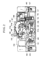
- Fig. 2 is a sectional side view along line II-II passing through the center poles in Fig. 1.
- an internal mechanism for breaking circuits is received in the molded case 100, and covered with the cover 200.
- the molded case 100 and the cover 200 protects the internal mechanism received inside, from foreign substances, dusts and so on, in a state where the molded case 100 and the cover 200 are combined as a body case, and, at the same time, they prevent a charging portion from being exposed so as to improve safety for an operator against a circuit breaker.
- the internal mechanism is constituted by a plurality of unit parts, that is, the arc-extinguishing chamber unit 400, the switching mechanism portion unit 500, the overcurrent tripper unit 600, and the current transformer (hereinafter simply abbreviated to "CT") 750.
- the CT 750 is used because the signal processor 619 for detecting overcurrent by using an electronic circuit is used in the overcurrent tripper unit 600 in this embodiment, the CT 750 cannot be used in the case of an overcurrent detector using a bimetal or oil dash-pot relay.
- the overcurrent tripper unit 600 has a relay unit case 622 in which the signal processor 619 and a part of the CT 750 are received.
- the signal processor 619 is constituted by a micro-computer and other electric parts which are mounted on a circuit board and electrically connected so as to perform predetermined functions.
- a coil 620 and a trip unit 621 of the CT are also electrically and mechanically connected to this circuit board through lead wires.
- a current of each phase detected by the CT 750 is supplied to the signal processor 619.
- the signal processor 619 judges whether the current value exceeds a predetermined level or not. When the current value exceeds the predetermined level, the signal processor 619 supplies a trip signal to the trip unit 621 connected to this signal processor 619.
- the trip unit 621 converts this trip signal into a mechanical output.
- the CT 750 is divided into the CT coil 620 constituted by a winding wound on a hollow bobbin, a U-shaped lower fixed core unit 700, and an I-shaped upper fixed core 701, so that the CT 750 can be assembled automatically.
- the CT coil 620 is electrically connected to the signal processor 619 in the relay unit case 622, and the upper fixed core 701 is inserted into the bobbin of the CT coil 620.
- the CT coil 620 and the upper fixed core 701 are received in the relay unit case 622.
- the upper fixed core 701 is held in the bobbin of the CT coil 620 or the relay unit case 622 so as to be opposite to the bottom side of the U shape of the lower fixed core unit.
- both the upper fixed core and the lower fixed core unit may be L-shaped and disposed point-symmetrically with each other so as to form a rectangular or square core.
- the upper fixed core may be U-shaped and the lower fixed core unit be I-shaped, so that they are combined to form a rectangular or square core.
- the bobbin of the CT coil 620 is attached to one of the horizontal and vertical sides of the L shape of the upper fixed core, and in the latter, the bobbin of the CT coil 620 is attached to one of two vertical sides of the U shape of the upper fixed core.
- the overcurrent tripper unit 600 in this embodiment respective parts are inserted and assembled into the relay unit case 622 from above in Fig. 11.
- the circuit board is inserted into the relay unit case 622 in the state in which the coil 620 and the trip unit 621 of the CT are attached on the circuit board in advance.
- An opening portion 623 (only the right side opening is shown in Fig. 11) and a lock portion of the upper fixed core 701 are formed in the lower portion of each side of the relay unit case 622 put in a state as shown in Fig. 11.
- the upper fixed core 701 of the CT When the upper fixed core 701 of the CT is inserted through this opening portion 623, the upper fixed core 701 is inserted into the bobbin of the CT coil 620, and, at the same time, the opposite ends of the upper fixed core 701 are locked to the relay unit case 622, so that the CT coil 620 and the upper fixed core 701 are attached to the relay unit case 622. Consequently, the signal processor 619, the CT coil 620 and the trip unit 621 are stored in the relay unit case 622 integrally.
- the respective constituent parts are assembled only in one direction in steps other than the step of inserting the upper fixed core 701 of the CT. Accordingly, assembly can be made by falling down parts from above.
- the configuration of the attachment portions of the CT core 620 and the upper fixed core 701 to the relay unit case 622 is not limited to this embodiment.
- the configuration may be changed such that the circuit board connected with the CT coil 620 to which the upper fixed core 701 is attached in advance is attached to the relay unit case 622.
- the structure and shape of the opening portion 623 and the lock portion of the upper fixed core 701 are changed suitably so that the upper fixed core 701, on which the CT coil 620 is mounted only by inserting the upper fixed core 701 from above, is locked by forming an elastic projection, and so on.
- the respective constituent parts can be assembled only in one direction, so that assembly by falling down parts from above can be realized.
- the lower fixed core unit 700 is disposed on the bottom portion of the molded case 100, and the upper fixed core 701 is disposed above the lower fixed core unit 700.
- the CT coil 620 is attached to this upper fixed core 701, and the CT coil 620 is integrated with the circuit board of the signal processor 619. Therefore, it is not necessary to carry out wiring onto the CT coil 620 when the CT 750 is mounted, whereby the workability is improved. In other words, in this embodiment, it is possible to provide CTs 750 suitable for automation in assembling of a product.
- a current value of any one of the three phases of an electric circuit can be calculated from current values of the other two phases so long as the use condition is an ordinary one, and, therefore, only two CTs 750 are used herein to thereby decrease the number of parts.
- the three-pole circuit breaker for a three-phase AC circuit is described in this embodiment, the present invention is not limited to this embodiment, but it may be applicable to a circuit breaker for a polyphase AC circuit having the signal processor 619 using a micro-computer and having the CTs 750 the number of which is less by one than the number of the phases of the circuit.
- the present invention may be applicable to a circuit breaker using only one CT 750. Further, in the case of a three-phase four-pole circuit breaker having a neutral line, it will do to provide CTs 750 in any two of the three poles in each of which a phase current flows.
- CTs 750 the number of which is less by one than the number of the phases are provided in poles, except a central pole, through which phase currents flow.
- the CTs 750 are disposed in two of the three poles except the central pole as shown in Figs. 3 and 11.
- the CTs 750 are disposed in two of the three poles, except a central pole, in which phase currents flow. In this way, since the weights of both the right and left sides of the central pole are balanced with each other, the circuit breaker can be stably mounted on a control panel or the like.
- FIG. 16 shows the output characteristic of the CT 750 while the abscissa axis represents a conduction current in the conductor 1, and the ordinate axis represents an output current of the CT 750.
- the CT 750 is configured to use only one CT coil 620.
- the output current tends to be saturated earlier in the region where the conduction current is large as indicated by an output characteristic curve A in Fig. 16.
- the output current is saturated with a conduction current smaller than that in the case of an output characteristic curve B in which a current is detected by using two CT coils 620 in the conventional case as disclosed, for example, in JP-A-5-135683.
- the region where the output current proportional to the conduction current can be extracted is narrowed, there is no problem in practice since the detected current value can be corrected by arithmetic operation based on the characteristic curve of the CT 750 in the case of using a micro-computer for controlling the timing characteristic like in this embodiment.
- the overcurrent tripper unit is constituted by using an electronic circuit in this embodiment
- the present invention is not limited to this embodiment, but it may be applicable to an overcurrent tripper unit in which a bimetal or oil dash-pot relay is used to generate a mechanical output at the time of overcurrent.
- the bimetal or oil dash-pot relay since it is necessary to make a load current flow in the bimetal or oil dash-pot relay, and therefore the bimetal or oil dash-pot relay is configured to be electrically connected in series between the load side of the arc-extinguishing chamber unit 400 and the load side terminal of the same.
- Fig. 3 is an exploded perspective view illustrating the shapes of respective units when the internal mechanism of the circuit breaker according to the present invention is constituted by unit parts. Fig. 3 also shows the order of assembling of the units.
- the molded case 100 is formed into a substantially rectangular shape, and one side surface thereof becomes a bottom face for preventing the received internal mechanism from coming off and for ensuring electric insulation of the internal mechanism.
- An opening portion 100a for receiving the internal mechanism therefrom is formed in the surface opposite to the bottom surface of the molded case 100.
- a groove portion 101 for receiving the lower fixed core unit 700, a plurality of spaces 102 defined by section walls 103 for respectively receiving the arc-extinguishing chamber units 400 corresponding to a plurality of poles, and a space 107 defined by walls for receiving the overcurrent tripper unit 600 are formed in the molded case 100.
- a wall notch portion 104 for receiving a rotary shaft 439 for coupling movable contact bases 431 disposed in adjacent arc-extinguishing chamber units 400, and groove portions 105 and 106 for receiving an insulation wall 601 extended from the overcurrent tripper unit 600 are formed.
- arc-extinguishing chamber units 400 for respective phases are formed by making contact portions and arc extinguishers be units.
- each arc-extinguishing chamber is formed in combination of an arc-extinguishing unit case 425 and an arc-extinguishing unit cover 424.
- a rotatably provided movable contact base 431, a pair of fixed contact bases 426 and 427, and a pair of arc shoots 428 are received in this arc-extinguishing chamber, so that the contact portion and the arc extinguisher are united as one arc-extinguishing chamber unit 400.
- the structure and assembling method of the arc-extinguishing chamber unit 400 for one phase will be explained specifically.
- the arc-extinguishing unit case 425 and the arc-extinguishing unit cover 424 are configured so that they can be combined to form a substantially rectangular arc-extinguishing chamber.
- the arc-extinguishing unit case 425 and the arc-extinguishing unit cover 424 are formed of insulating substances having an enough strength to endure pressure of arc gas in breaking respectively.
- the insulating substances specifically thermosetting resin such as polyester, phenol, epoxy; ceramic; or the like may be used. These materials are larger in heat resistance and mechanical strength than thermoplastic resin such as nylon or the like used for the molded case 100 and the cover 200.
- the movable contact base 431 has a rotation center, and has two movable contact points 432 disposed in point-symmetrical positions with respect to this rotation center and connected in series electrically.
- a positioning hole is provided at the rotation center of the movable contact base 431, and a projection formed at the rotation center of a movable contact point protecting cover 430 is fitted into this positioning hole, so that the movable contact point protecting cover 430 is attached onto one side surface (lower side surface in Fig. 12) of the movable contact base 431.
- a movable contact point protecting cover 429 is attached onto the other side surface (upper side surface in Fig. 12) of the movable contact base 431.
- the projection formed at the rotation center of the movable contact point protecting cover 430 is passed through the positioning hole of the movable contact base 431 so as to be inserted into a positioning hole formed at the rotation center of the movable contact point protecting cover 429. Consequently, the movable contact base 431 and the movable contact point protecting covers 429 and 430 are combined integrally to thereby constitute a movable contact unit 460.
- the movable contact point protecting covers 429 and 430 may be formed of thermosetting resin such as polyester, phenol, epoxy; ceramic; and so on.
- the fixed contact base 426 is formed in the shape of a question mark, i.e. "?".
- a power supply side terminal is formed in the portion corresponding to the lower-side straight line portion at one end of the "?" shape, and a fixed contact point 433 corresponding to one of the movable contact points 432 of the movable contact base 431 is provided in the portion corresponding to the folded inside top end at the other end of the "?" shape.
- a terminal screw 490 for clamping an electric wire is attached to the power supply side terminal.
- the fixed contact base 427 is also formed in the shape of "?".
- a load side terminal is formed in the portion corresponding to the lower-side straight line portion at one end of the "?" shape, and a fixed contact point 433 corresponding to the other movable contact point 432 of the movable contact base 431 is provided in the portion corresponding to the folded inside top end at the other end of the "?" shape.
- a terminal screw 490 for clamping an electric wire is also attached to the load side terminal.
- the rotation center portions on their sides opposite to their sides facing the movable contact base 431 are exposed from connection holes 424a and 425a formed in the arc-extinguishing unit cover 424 and the arc-extinguishing unit case 425 respectively.
- the movable contact unit 460 is held rotatably between the arc-extinguishing unit case 425 and the arc-extinguishing unit cover 424, so that the movable contact base 431 is held rotatably about the rotation center thereof.
- a concave portion 429a for fitting a coupling member 439 is formed in each of the portions of the movable contact unit 460 exposed from the connection holes 424a and 425a.
- Such coupling members 439 are interposed between the movable contact units 460 for respective poles to transmit the operation of on-off-trip of the switching mechanism portion unit 500 to the movable contact units 460 for the respective poles substantially at the same time.
- Each of the coupling members 439 which is formed of insulating material, for example, thermosetting resin such as polyester, phenol, epoxy; ceramic; and so on has an arm portion 439a through which the operation of the switching mechanism portion unit 500 is transmitted, and a convex portion 439b attached to the concave portion 429a of the movable contact unit 460.
- the coupling members 439 are arranged so as to rotate around the same rotation center as the movable contact units 460, and rotate the movable contact units 460 for a plurality of poles substantially simultaneously by inserting their convex portions 439b into the concave portions 429a of the movable contact units 460.
- the shape of the convex portion 439b of each coupling member 439 and the concave portion 429a of each movable contact unit 460 are formed into a shape, for example, a polygon, by which transmission delay of a rotation force is not produced by sliding when the convex portion 439b is inserted into and coupled with the concave portion 429a.
- a shape for example, a polygon
- the shape is equilaterally hexagonal in this embodiment, it may be triangular or quadrangular.
- Positioning projections for grids of the arc chutes 428 are provided in positions of the inner sides of the arc-extinguishing unit case 425 and the arc-extinguishing unit cover 424 near the fixed contact point 433 and the movable contact 432. In this way, it is possible to attach the magnetic plates to the arc-extinguishing unit case 425 and the arc-extinguishing unit cover 424 only by making the magnetic plates engage with the positioning projections respectively, so that it is possible to assemble the arc shoots 428 into arc-extinguishing chambers together with the fixed contact bases 426 and 427 and the movable contact unit 460.
- an L-shaped movable core 438 is built in the arc-extinguishing unit cover 425 as shown in Figs. 2 and 3, and a U-shaped instantaneous tripping fixed core 434 is mounted on the load-side fixed contact base 427 as shown in Fig. 12.
- a magnetic circuit is formed between the instantaneous tripping fixed core 434 and a bottom side 438a of the L-shape of the instantaneous tripping movable core 438 when a large current flows, and the bottom side 438a is attracted by an electromagnetic force so that the instantaneous tripping movable core 438 rotates counterclockwise in Fig.
- an engagement arm 438b formed on the other side of the L-shape of the instantaneous tripping movable core 438 also rotates counterclockwise in Fig. 2.
- the engagement arm 438b engages with a transmission lever 522 of the switching mechanism portion unit 500 so as to rotate counterclockwise to thereby mechanically trip the switching mechanism portion unit 500. Consequently, instantaneous tripping operations for the respective phases are performed substantially simultaneously.
- Fig. 10 The structure and assembling steps of the switching mechanism portion unit 500 will be described by using Fig. 10.
- names of respective parts arranged in pair will be distinguished by attaching the words such as upper and lower, right and left, and so on, in the arrangement in Fig. 10.
- these words such as upper and lower, right and left, and so on, are used not for limiting the present invention but only for specifying parts in the description of the embodiment of the present invention. This point applies also to other drawings.
- the switching mechanism portion unit 500 has a link mechanism for switching the movable contact units 440 in the arc-extinguishing chambers 400 by the manual operation of the handle 300, and a trip mechanism for tripping the link mechanism by a mechanical output from the trip unit 621 of the overcurrent tipper unit 600 at the time of an electrically abnormal condition such as overcurrent.
- the link mechanism and the trip mechanism are mounted between left and right fixed frames 508 and 518.
- the link mechanism is constituted by a handle lever 512 to which a spring force is given by a driving spring 511, a hook 509 for keeping an upper lever 515 and a lower lever 517 substantially on a straight line in a normal on-off state, and the upper and lower levers 515 and 517 coupled with each other through a lever pin 516.
- the handle 300 is attached to an upper portion 512a of the handle lever 512 as shown in Figs. 2 and 7.
- the trip mechanism is constituted by a transmission lever 522, a trip lever 514, and a trip member 510.
- the trip lever 514 has a substantially L-shaped side shape, and is rotatably supported between the left and right frames 508 and 518 near the bent portion of the L-shape of the trip lever 514.
- the vertical side of the L-shape of the trip lever 514 extends downward, and the horizontal side extends to the left.
- the transmission lever 522 is attached on the vertical side of the L-shape of the trip lever 514 near its lower end portion in parallel with the rotation axis of the trip lever 514.
- the transmission lever 522 has length enough to engage with the engagement arms 438b of the instantaneous tripping movable cores 438 for the respective poles in this embodiment.
- the transmission lever 522 picks up not only the operations of the instantaneous tripping movable cores 438 for the respective poles, but also the operation of the trip unit 621 by engaging with the trip unit 621 of the overcurrent tripper unit 600 in the central pole portion.
- the engagement arms 438b and the trip unit 621 give a force substantially horizontally leftward in Fig. 10 to the transmission lever 522 through their operation upon detection of an overcurrent, so that the trip lever 514 is rotated counterclockwise.
- An engagement portion 514a for engaging with the trip member 510 is formed near the bent portion of the trip lever 514.
- the plate-like formed trip member 510 is rotatably supported at its lower end portion between the left and right fixed frames 508 and 518 and under the supported portion of the trip lever 514.
- a spring force is given to the trip member 510 by a return spring 513 so that the trip member 510 rotates clockwise in Fig. 10 or Fig. 2.
- An opening portion 510a is formed in the center portion of the plate-like portion of the trip member 510.
- the engagement portion 514a of the trip lever 514 engages with the upper end portion of the trip member 510 to prevent the clockwise rotation of the trip member 510.
- Projection portions 519 formed at one ends of the hook 509 are inserted into lever receiving portions 520 of the left and right fixed frames so that the hook 509 is rotatably supported between the left and right fixed frames 508.
- the other end of the hook 509 extends into the opening portion 510a of the trip member 510 to engage with the upper end of the opening portion 510a so as to prevent counterclockwise rotations of the hook 509.
- the upper end portion of the upper lever 515 is rotatably supported at a substantially center portion of the hook 509 while the lower end portion of the upper lever 515 is rotatably coupled with the lower lever 517 through the pin 516.
- the lower end portion of the lower lever 517 is rotatably coupled with the coupling member 439.
- Driving springs 511 are stretched between the handle 300 mounting portion of the handle lever 512 and the pin 516 to give a counterclockwise rotation force to the hook 509.
- the handle 300 and the transmission lever 522 are formed of insulating material such as resin, ceramic and so on, and the other parts are mainly formed of steel plates. In this embodiment, since the coupling member 439 and the transmission lever 522 are of insulating materials, the switching mechanism portion unit 500 becomes a non-charged portion, so that safety in maintenance, inspection and so on is improved.
- this switching mechanism portion unit 500 To assemble this switching mechanism portion unit 500, the left fixed frame 508 is used as a base, the trip member 510 mounted with the return spring 513 and the trip lever 514 are incorporated in advance. Next, the lower end of the handle lever 512 is engaged with the projecting portion 519 of the hook 509 rotatably, and the upper end portion of the upper lever 515 coupled with the lower lever 517 through the pin 516 is engaged with the substantially center portion of the hook 509 rotatably. Next, an assembly in which the driving spring 511 is stretched between the handle 300 attachment portion of the handle lever 512 and the pin 516 is prepared, and this assembly is incorporated into the left fixed frame 508 used as a base.
- the right fixed frame 518 is put thereon, and the hook 509, the trip member 510 and the trip lever 514 are rotatably supported between the left and right fixed frames 508 and 518.
- the left and right fixed frames 508 and 518 are caulked, and the assembling is completed.
- the switching mechanism portion unit 500 is incorporated in the direction toward the left fixed frame 508, so that assembling in one direction can be realized.
- the left fixed frame 508 is put on downside and the respective parts are incorporated downward, it is possible to realize assembling in a falling down system.
- the passage "the direction along the direction of opening of a cover” is used in the following meaning. That is, the passage “the direction along the direction of opening of a cover” means the direction in which the cover 200 is put on the molded case 100 in the circuit breaker which has been assembled. That is, the passage “the direction along the direction of opening of a cover” means the vertical direction (up/down direction) when assembling is performed in the condition that the molded case 100 is laid horizontally, and, not to say, the passage means a horizontal direction when assembling is performed as the molded case 100 is laid vertically. Therefore, the passage "the direction along the direction of opening of a cover” means the vertical direction in Fig.
- assembling of respective unit parts in "the direction along the direction of opening of a cover” means assembling of the unit parts while mounting the unit parts onto the molded case 100 in the vertical direction, and particularly in the case where the molded case 100 is provided with its bottom downside, it means that the respective unit parts are assembled while the unit parts are fallen down.
- the internal mechanism is constituted by the above-mentioned respective unit parts, so that assembling is attained in the following steps.
- circuit breaker can be assembled automatically with units, but also each unit can be assembled automatically with parts.
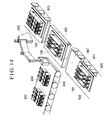
- arc-extinguishing chamber units are incorporated in a body case (corresponding to the above step (2)).
- the body case 100 is conveyed by a conveyor 801 in a condition that it is put on a positioning pallet 805.
- the lower fixed core unit 700 of the CT has been already fallen down and incorporated in the step (1).
- Control pieces 806 and 807 for controlling the position where the body case 100 is to be mounted are provided in the pallet 805 to thereby control the position of the body case into a predetermined position when unit parts are fallen down.
- the pallet 805 mounted with the body case 100 is conveyed to an assembling station 802 by a desired means.
- An assembling robot 800 is provided near the assembling station 802.
- the arc-extinguishing chamber units 400 for three poles coupled with each other are conveyed toward the assembling station 802 by a conveyor 804 disposed perpendicularly to the assembling station 802.
- the assembling robot 800 holds the arc-extinguishing chamber units 400 coupled with each other, conveys them above the body case 100, and thereafter makes them fall down into the body case 100.
- the body case 100 in which the arc-extinguishing chamber units 400 have been incorporated is put on a conveyor 803 by a suitable means, and the assembling work goes to the next step (3).
- Fig. 2 shows the ON state of the circuit breaker.
- the toggle link of the switching mechanism portion unit 500 is operated to bring the movable contact bases 431 into the OFF state.
- the handle 300 is rotated counterclockwise on the contrary to the above OFF operation, so that the toggle link of the switching mechanism portion unit 500 is operated to bring the movable contact bases 431 into the ON state.
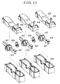
- Fig. 13 shows an arc-extinguishing chamber unit 400 of a circuit breaker in a second embodiment of the present invention.
- the arc-extinguishing chamber unit itself is assembled vertically or in the up/down direction in the same manner as the molded case 100 and the body cover 200.
- the other parts are similar to those in the first embodiment, and therefore their illustration and description are omitted.
- the arc-extinguishing chamber unit 400 is constituted by an arc-extinguishing chamber case 436, an arc-extinguishing chamber cover 435, and a movable contact unit 465.
- a movable contact base 431 has a pair of movable contact points 432 in point-symmetric positions with respect to its rotation center.
- a coupling shaft 437 rotatably supporting the movable contact base 431 between the arc-extinguishing chamber case 436 and the arc-extinguishing chamber cover 435 is fitted to the rotation center of the movable contact base 431.
- This coupling shaft 437 is formed of insulating material such as resin, ceramic and so on.
- a fixed contact base is not illustrated in Fig. 13, and the same fixed contact base as that in the first embodiment is used.
- An instantaneous tripping movable core 438 which can be tripped instantaneously when a large current flows is incorporated in the arc-extinguishing chamber cover 435 in the same manner as in the first embodiment.
- FIG. 13 A coupling shaft 437 rotatably supporting the movable contact base 431 between the arc-extinguishing chamber case 436 and the arc-extinguishing chamber cover 435 is fitted to the rotation center of the movable contact base 431.
- This coupling shaft 437 is formed of
- an instantaneous tripping fixed core is mounted on the load-side fixed contact base in the same manner as in the first embodiment.
- a coupling member 439 is interposed between the coupling shafts 437 of the respective arc-extinguishing chamber units so as to couple the arc-extinguishing chamber units with each other. Consequently, tripping and switching of the respective phases can be performed substantially simultaneously.
Abstract
Description
- The present invention relates to a circuit breaker in which respective constituent parts are formed as units, and particularly to a circuit breaker in which respective units are configured to be able to be inserted and incorporated into a molded case sequentially in one direction preferably to improve the efficiency of automation in assembling.
- Further, the present invention relates to a manufacturing method of a circuit breaker in which respective constituent parts of the circuit breaker are formed as units so as to realize automation in assembling, and particularly to a manufacturing method of a circuit breaker in which respective constituent units are all incorporated in one direction of a product along the open direction of a cover.
- A conventional circuit breaker is constituted by numbers of parts. For example, as disclosed in Fig. 1 of JP-A-4-190521, a conventional circuit breaker is constituted by a single mechanism in which individual parts are assembled with each other directly. Accordingly, assembling operation both in the right and left direction and in the up/down direction is required in assembling, and it is therefore difficult to realize automation in assembling a circuit breaker.
- Further, a circuit breaker constituted by standard unipolar units is disclosed in JP-A-5-217489, in which assembling operation both in the right and left direction and in the up/down direction is required in assembling, so that the circuit breaker is not sufficiently suitable for automation in assembling.
- The present invention seeks to provide a circuit breaker which may be divided into blocks as units so as to be suitable for automation in assembling, and configured in such a manner'that the respective units can be inserted and incorporated into a molded case sequentially in one direction so as to improve the efficiency of automation in assembling.
- The present invention also seeks to provide a manufacturing method of a circuit breaker in which respective parts of a circuit breaker may be united into units, and all the respective units are sequentially inserted and incorporated in a molded case in one direction along the open direction of a cover so that the efficiency of automation in assembling is improved.
- In order to attain the foregoing objects, the present invention provides a circuit breaker which is divided into blocks of a molded case, a cover, an arc-extinguishing chamber unit, a switching mechanism portion unit, an overcurrent tripper unit and a manually operating handle. Preferably the arc-extinguishing chamber unit, the switching mechanism portion unit and the overcurrent tripper unit are assembled as units in advance so that the respective units can be sequentially inserted and incorporated in the molded case in one direction.
- In a preferred embodiment, the overcurrent tripper unit has a current transformer (hereinafter abbreviated to "CT") for detecting a current flowing in each phase, and a core of the CT is divided into a U-shaped lower fixed core unit and an I-shaped upper fixed core.
- Further, the present invention may provide manufacturing method of a circuit breaker which is divided into blocks of a molded case, a cover, an arc-extinguishing chamber unit, a switching mechanism portion unit, an overcurrent tripper unit and a manually operating handle. The arc-extinguishing chamber unit, the switching mechanism portion unit and the overcurrent tripper unit are assembled as units in advance, and in which the core of a CT of the overcurrent tripper unit is divided into a lower fixed core unit and an upper fixed core. The respective units are incorporated in the molded case in one direction along the open direction of the cover in the order of the lower fixed core unit of the CT, the arc-extinguishing chamber unit, the switching mechanism portion unit, the manually operating handle, the overcurrent tripper unit, and the cover.
- Furthermore, the present invention may provide manufacturing method of a circuit breaker which is divided into blocks of a molded case, a cover, an arc-extinguishing chamber unit, a switching mechanism portion unit, an overcurrent tripper unit and a manually operating handle. The arc-extinguishing chamber unit, the switching mechanism portion unit and the overcurrent tripper unit being assembled as units in advance. The core of a CT of the overcurrent tripper unit is divided into a lower fixed core unit and an upper fixed core, so that in total assembling, all the respective units are incorporated in the molded case in one direction along the open direction of the cover.
- The following effects may be obtained according to the present invention.
- (1) Mechanization of automatic assembling is made easy by making the respective parts be units.
- (2) Mechanization of automatic assembling is made easy because of the structure in which all the units can be incorporated in the state in which the cover is open.
- (3) A machine for automation in assembling can be operated in one direction which is the gravitational direction, so that it is possible to simplify the assembling machine to thereby improve the reliability.
- (4) Specification can be changed easily between an electronic overcurrent trip system and a mechanical overcurrent trip system because of the structure in which the respective parts are made to be units.
-
- Fig. 1 is a plan view illustrating the outline of a circuit breaker in a first embodiment of the present invention;
- Fig. 2 is a sectional side view illustrating the configuration of the circuit breaker in the first embodiment of the present invention;
- Fig. 3 is an exploded perspective view illustrating the directions in which respective unit parts of the circuit breaker in the first embodiment of the present invention are attached;
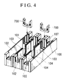
- Fig. 4 is an exploded perspective view illustrating the state in which a CT lower fixed core of the circuit breaker in the first embodiment of the present invention is attached to the molded case;
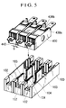
- Fig. 5 is an exploded perspective view illustrating the state in which the arc-extinguishing chamber unit of the circuit breaker in the first embodiment of the present invention is attached to the molded case;
- Fig. 6 is an exploded perspective view illustrating the state in which a switching mechanism portion unit of the circuit breaker in the first embodiment of the present invention is attached to the molded case;
- Fig. 7 is an exploded perspective view illustrating the state in which a manually operating handle of the circuit breaker in the first embodiment of the present invention is attached to the molded case;
- Fig. 8 is an exploded perspective view illustrating the state in which an overcurrent tripper unit of the circuit breaker in the first embodiment of the present invention is attached to the molded case;
- Fig. 9 is an exploded perspective view illustrating the state in which a cover of the circuit breaker in the first embodiment of the present invention is fallen down and thereby attached to the molded case;
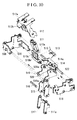
- Fig. 10 is an exploded perspective view illustrating constituent parts and their assembling directions of the switching mechanism portion unit of the circuit breaker in the first embodiment of the present invention;
- Fig. 11 is an exploded perspective view illustrating constituent parts and their assembling directions of the overcurrent tripper unit of the circuit breaker in the first embodiment of the present invention;
- Fig. 12 is an exploded perspective view illustrating constituent parts and their assembling directions of the arc-extinguishing chamber unit of the circuit breaker in the first embodiment of the present invention;
- Fig. 13 is an exploded perspective view illustrating constituent parts and their assembling directions of an arc-extinguishing chamber unit of a circuit breaker in a second embodiment of the present invention;
- Fig. 14 is a perspective view illustrating an example of assembling method of the circuit breaker in the first embodiment of the present invention;
- Fig. 15 is a block diagram of an electric circuit of the circuit breaker in the first embodiment of the present invention; and
- Fig. 16 is a CT output characteristic diagram of the circuit breaker in the first embodiment of the present invention.
- Embodiments of the structure and assembling method of a circuit breaker according to the present invention will be described below with reference to the drawings.
- A structure and an assembling method of a circuit breaker in a first embodiment of the present invention will be described with reference to Figs. 1 to 12, Fig. 14 and Fig. 15.
- The circuit breaker of this embodiment shown in Fig. 15 has a current transformer (hereinafter abbreviated to "CT") 750 for detecting a current flowing in a conductor 1 of an electric circuit, a
signal processor 619 for controlling a trip operation on the basis of a current value detected by thisCT 750, and atrip unit 621, theparts case 100. - In this embodiment, the circuit breaker is divided into blocks of the
molded case 100, acover 200, an arc-extinguishing chamber unit 400, a switchingmechanism portion unit 500, anovercurrent tripper unit 600, and a manuallyoperating handle 300. The arc-extinguishing chamber unit 400, the switchingmechanism portion unit 500 and theovercurrent tripper unit 600 are configured as units in advance so that the respective units can be sequentially inserted and assembled in the moldedcase 100 in one direction. - Fig. 1 is an outline plan view of the circuit breaker according to this embodiment viewed from its top. Fig. 2 is a sectional side view along line II-II passing through the center poles in Fig. 1.
- In the circuit breaker according to this embodiment, an internal mechanism for breaking circuits is received in the molded
case 100, and covered with thecover 200. The moldedcase 100 and thecover 200 protects the internal mechanism received inside, from foreign substances, dusts and so on, in a state where the moldedcase 100 and thecover 200 are combined as a body case, and, at the same time, they prevent a charging portion from being exposed so as to improve safety for an operator against a circuit breaker. The internal mechanism is constituted by a plurality of unit parts, that is, the arc-extinguishing chamber unit 400, the switchingmechanism portion unit 500, theovercurrent tripper unit 600, and the current transformer (hereinafter simply abbreviated to "CT") 750. Incidentally, although theCT 750 is used because thesignal processor 619 for detecting overcurrent by using an electronic circuit is used in theovercurrent tripper unit 600 in this embodiment, theCT 750 cannot be used in the case of an overcurrent detector using a bimetal or oil dash-pot relay. - In this embodiment, the
overcurrent tripper unit 600 has arelay unit case 622 in which thesignal processor 619 and a part of theCT 750 are received. Thesignal processor 619 is constituted by a micro-computer and other electric parts which are mounted on a circuit board and electrically connected so as to perform predetermined functions. Acoil 620 and atrip unit 621 of the CT are also electrically and mechanically connected to this circuit board through lead wires. A current of each phase detected by theCT 750 is supplied to thesignal processor 619. Thesignal processor 619 judges whether the current value exceeds a predetermined level or not. When the current value exceeds the predetermined level, thesignal processor 619 supplies a trip signal to thetrip unit 621 connected to thissignal processor 619. Thetrip unit 621 converts this trip signal into a mechanical output. - In this embodiment, the
CT 750 is divided into theCT coil 620 constituted by a winding wound on a hollow bobbin, a U-shaped lowerfixed core unit 700, and an I-shaped upper fixedcore 701, so that theCT 750 can be assembled automatically. TheCT coil 620 is electrically connected to thesignal processor 619 in therelay unit case 622, and the upper fixedcore 701 is inserted into the bobbin of theCT coil 620. In theCT 750, therefore, theCT coil 620 and the upper fixedcore 701 are received in therelay unit case 622. At this time, the upper fixedcore 701 is held in the bobbin of theCT coil 620 or therelay unit case 622 so as to be opposite to the bottom side of the U shape of the lower fixed core unit. - The division of the core of the
CT 750 is not limited to this, and both the upper fixed core and the lower fixed core unit may be L-shaped and disposed point-symmetrically with each other so as to form a rectangular or square core. In addition, the upper fixed core may be U-shaped and the lower fixed core unit be I-shaped, so that they are combined to form a rectangular or square core. In the former, the bobbin of theCT coil 620 is attached to one of the horizontal and vertical sides of the L shape of the upper fixed core, and in the latter, the bobbin of theCT coil 620 is attached to one of two vertical sides of the U shape of the upper fixed core. - The process to assemble the
overcurrent tripper unit 600 will be explained with reference to Fig. 11. - In the
overcurrent tripper unit 600 in this embodiment, respective parts are inserted and assembled into therelay unit case 622 from above in Fig. 11. The circuit board is inserted into therelay unit case 622 in the state in which thecoil 620 and thetrip unit 621 of the CT are attached on the circuit board in advance. An opening portion 623 (only the right side opening is shown in Fig. 11) and a lock portion of the upper fixedcore 701 are formed in the lower portion of each side of therelay unit case 622 put in a state as shown in Fig. 11. When the upper fixedcore 701 of the CT is inserted through thisopening portion 623, the upper fixedcore 701 is inserted into the bobbin of theCT coil 620, and, at the same time, the opposite ends of the upper fixedcore 701 are locked to therelay unit case 622, so that theCT coil 620 and the upper fixedcore 701 are attached to therelay unit case 622. Consequently, thesignal processor 619, theCT coil 620 and thetrip unit 621 are stored in therelay unit case 622 integrally. In this embodiment, the respective constituent parts are assembled only in one direction in steps other than the step of inserting the upper fixedcore 701 of the CT. Accordingly, assembly can be made by falling down parts from above. - The configuration of the attachment portions of the
CT core 620 and the upper fixedcore 701 to therelay unit case 622 is not limited to this embodiment. The configuration may be changed such that the circuit board connected with theCT coil 620 to which the upper fixedcore 701 is attached in advance is attached to therelay unit case 622. In this case, the structure and shape of theopening portion 623 and the lock portion of the upper fixedcore 701 are changed suitably so that the upper fixedcore 701, on which theCT coil 620 is mounted only by inserting the upper fixedcore 701 from above, is locked by forming an elastic projection, and so on. With such a configuration, the respective constituent parts can be assembled only in one direction, so that assembly by falling down parts from above can be realized. - In addition, the lower fixed
core unit 700 is disposed on the bottom portion of the moldedcase 100, and the upper fixedcore 701 is disposed above the lower fixedcore unit 700. TheCT coil 620 is attached to this upper fixedcore 701, and theCT coil 620 is integrated with the circuit board of thesignal processor 619. Therefore, it is not necessary to carry out wiring onto theCT coil 620 when theCT 750 is mounted, whereby the workability is improved. In other words, in this embodiment, it is possible to provideCTs 750 suitable for automation in assembling of a product. - That is, in such a circuit breaker in which timing characteristic is controlled by the
signal processor 619 using a micro-computer as in this embodiment, a current value of any one of the three phases of an electric circuit can be calculated from current values of the other two phases so long as the use condition is an ordinary one, and, therefore, only twoCTs 750 are used herein to thereby decrease the number of parts. Although the three-pole circuit breaker for a three-phase AC circuit is described in this embodiment, the present invention is not limited to this embodiment, but it may be applicable to a circuit breaker for a polyphase AC circuit having thesignal processor 619 using a micro-computer and having theCTs 750 the number of which is less by one than the number of the phases of the circuit. Further, in the case of a single-phase circuit, the present invention may be applicable to a circuit breaker using only oneCT 750. Further, in the case of a three-phase four-pole circuit breaker having a neutral line, it will do to provideCTs 750 in any two of the three poles in each of which a phase current flows. - In the case where the number of phases of a polyphase AC circuit is odd,
CTs 750 the number of which is less by one than the number of the phases are provided in poles, except a central pole, through which phase currents flow. In this embodiment, theCTs 750 are disposed in two of the three poles except the central pole as shown in Figs. 3 and 11. Also in the case of the three-phase four-pole circuit breaker having a neutral line, theCTs 750 are disposed in two of the three poles, except a central pole, in which phase currents flow. In this way, since the weights of both the right and left sides of the central pole are balanced with each other, the circuit breaker can be stably mounted on a control panel or the like. - An output characteristic of the
CT 750 will be explained with reference to Fig. 16. Fig. 16 shows the output characteristic of theCT 750 while the abscissa axis represents a conduction current in the conductor 1, and the ordinate axis represents an output current of theCT 750. In this embodiment, theCT 750 is configured to use only oneCT coil 620. As a result, in this embodiment, the output current tends to be saturated earlier in the region where the conduction current is large as indicated by an output characteristic curve A in Fig. 16. The output current is saturated with a conduction current smaller than that in the case of an output characteristic curve B in which a current is detected by using twoCT coils 620 in the conventional case as disclosed, for example, in JP-A-5-135683. - That is, although the region where the output current proportional to the conduction current can be extracted is narrowed, there is no problem in practice since the detected current value can be corrected by arithmetic operation based on the characteristic curve of the
CT 750 in the case of using a micro-computer for controlling the timing characteristic like in this embodiment. - Although the overcurrent tripper unit is constituted by using an electronic circuit in this embodiment, the present invention is not limited to this embodiment, but it may be applicable to an overcurrent tripper unit in which a bimetal or oil dash-pot relay is used to generate a mechanical output at the time of overcurrent. In this case, since it is necessary to make a load current flow in the bimetal or oil dash-pot relay, and therefore the bimetal or oil dash-pot relay is configured to be electrically connected in series between the load side of the arc-extinguishing
chamber unit 400 and the load side terminal of the same. - Fig. 3 is an exploded perspective view illustrating the shapes of respective units when the internal mechanism of the circuit breaker according to the present invention is constituted by unit parts. Fig. 3 also shows the order of assembling of the units.
- As shown in Fig. 3, the molded
case 100 is formed into a substantially rectangular shape, and one side surface thereof becomes a bottom face for preventing the received internal mechanism from coming off and for ensuring electric insulation of the internal mechanism. Anopening portion 100a for receiving the internal mechanism therefrom is formed in the surface opposite to the bottom surface of the moldedcase 100. Agroove portion 101 for receiving the lower fixedcore unit 700, a plurality ofspaces 102 defined bysection walls 103 for respectively receiving the arc-extinguishingchamber units 400 corresponding to a plurality of poles, and aspace 107 defined by walls for receiving theovercurrent tripper unit 600 are formed in the moldedcase 100. In each of thesection walls 103, awall notch portion 104 for receiving arotary shaft 439 for couplingmovable contact bases 431 disposed in adjacent arc-extinguishingchamber units 400, andgroove portions insulation wall 601 extended from theovercurrent tripper unit 600 are formed. - In this embodiment, as shown in Fig. 12, arc-extinguishing
chamber units 400 for respective phases are formed by making contact portions and arc extinguishers be units. Specifically, each arc-extinguishing chamber is formed in combination of an arc-extinguishingunit case 425 and an arc-extinguishingunit cover 424. A rotatably providedmovable contact base 431, a pair of fixedcontact bases chamber unit 400. - The structure and assembling method of the arc-extinguishing
chamber unit 400 for one phase will be explained specifically. The arc-extinguishingunit case 425 and the arc-extinguishingunit cover 424 are configured so that they can be combined to form a substantially rectangular arc-extinguishing chamber. The arc-extinguishingunit case 425 and the arc-extinguishingunit cover 424 are formed of insulating substances having an enough strength to endure pressure of arc gas in breaking respectively. As the insulating substances specifically thermosetting resin such as polyester, phenol, epoxy; ceramic; or the like may be used. These materials are larger in heat resistance and mechanical strength than thermoplastic resin such as nylon or the like used for the moldedcase 100 and thecover 200. - The
movable contact base 431 has a rotation center, and has two movable contact points 432 disposed in point-symmetrical positions with respect to this rotation center and connected in series electrically. A positioning hole is provided at the rotation center of themovable contact base 431, and a projection formed at the rotation center of a movable contactpoint protecting cover 430 is fitted into this positioning hole, so that the movable contactpoint protecting cover 430 is attached onto one side surface (lower side surface in Fig. 12) of themovable contact base 431. A movable contactpoint protecting cover 429 is attached onto the other side surface (upper side surface in Fig. 12) of themovable contact base 431. The projection formed at the rotation center of the movable contactpoint protecting cover 430 is passed through the positioning hole of themovable contact base 431 so as to be inserted into a positioning hole formed at the rotation center of the movable contactpoint protecting cover 429. Consequently, themovable contact base 431 and the movable contact point protecting covers 429 and 430 are combined integrally to thereby constitute amovable contact unit 460. The movable contact point protecting covers 429 and 430 may be formed of thermosetting resin such as polyester, phenol, epoxy; ceramic; and so on. - The fixed
contact base 426 is formed in the shape of a question mark, i.e. "?". A power supply side terminal is formed in the portion corresponding to the lower-side straight line portion at one end of the "?" shape, and a fixedcontact point 433 corresponding to one of the movable contact points 432 of themovable contact base 431 is provided in the portion corresponding to the folded inside top end at the other end of the "?" shape. Aterminal screw 490 for clamping an electric wire is attached to the power supply side terminal. The fixedcontact base 427 is also formed in the shape of "?". A load side terminal is formed in the portion corresponding to the lower-side straight line portion at one end of the "?" shape, and a fixedcontact point 433 corresponding to the othermovable contact point 432 of themovable contact base 431 is provided in the portion corresponding to the folded inside top end at the other end of the "?" shape. Aterminal screw 490 for clamping an electric wire is also attached to the load side terminal. - Since the fixed contact points 433 corresponding to the respective movable contact points 432 are provided in this embodiment, it is possible to abolish flexible conductors used conventionally.
- As for the movable contact point protecting covers 429 and 430 of the
movable contact unit 460, the rotation center portions on their sides opposite to their sides facing themovable contact base 431 are exposed fromconnection holes unit cover 424 and the arc-extinguishingunit case 425 respectively. Themovable contact unit 460 is held rotatably between the arc-extinguishingunit case 425 and the arc-extinguishingunit cover 424, so that themovable contact base 431 is held rotatably about the rotation center thereof. Aconcave portion 429a for fitting acoupling member 439 is formed in each of the portions of themovable contact unit 460 exposed from theconnection holes Such coupling members 439 are interposed between themovable contact units 460 for respective poles to transmit the operation of on-off-trip of the switchingmechanism portion unit 500 to themovable contact units 460 for the respective poles substantially at the same time. Each of thecoupling members 439, which is formed of insulating material, for example, thermosetting resin such as polyester, phenol, epoxy; ceramic; and so on has anarm portion 439a through which the operation of the switchingmechanism portion unit 500 is transmitted, and aconvex portion 439b attached to theconcave portion 429a of themovable contact unit 460. Thecoupling members 439 are arranged so as to rotate around the same rotation center as themovable contact units 460, and rotate themovable contact units 460 for a plurality of poles substantially simultaneously by inserting theirconvex portions 439b into theconcave portions 429a of themovable contact units 460. The shape of theconvex portion 439b of eachcoupling member 439 and theconcave portion 429a of eachmovable contact unit 460 are formed into a shape, for example, a polygon, by which transmission delay of a rotation force is not produced by sliding when theconvex portion 439b is inserted into and coupled with theconcave portion 429a. Although the shape is equilaterally hexagonal in this embodiment, it may be triangular or quadrangular. - Positioning projections for grids of the
arc chutes 428 are provided in positions of the inner sides of the arc-extinguishingunit case 425 and the arc-extinguishingunit cover 424 near the fixedcontact point 433 and themovable contact 432. In this way, it is possible to attach the magnetic plates to the arc-extinguishingunit case 425 and the arc-extinguishingunit cover 424 only by making the magnetic plates engage with the positioning projections respectively, so that it is possible to assemble the arc shoots 428 into arc-extinguishing chambers together with the fixedcontact bases movable contact unit 460. - In addition, an L-shaped
movable core 438 is built in the arc-extinguishingunit cover 425 as shown in Figs. 2 and 3, and a U-shaped instantaneous trippingfixed core 434 is mounted on the load-side fixedcontact base 427 as shown in Fig. 12. A magnetic circuit is formed between the instantaneous trippingfixed core 434 and abottom side 438a of the L-shape of the instantaneous trippingmovable core 438 when a large current flows, and thebottom side 438a is attracted by an electromagnetic force so that the instantaneous trippingmovable core 438 rotates counterclockwise in Fig. 2 around the bent portion of the L-shape of the instantaneous trippingmovable core 438. As a result, anengagement arm 438b formed on the other side of the L-shape of the instantaneous trippingmovable core 438 also rotates counterclockwise in Fig. 2. When the switchingmechanism portion unit 500 is attached, theengagement arm 438b engages with atransmission lever 522 of the switchingmechanism portion unit 500 so as to rotate counterclockwise to thereby mechanically trip the switchingmechanism portion unit 500. Consequently, instantaneous tripping operations for the respective phases are performed substantially simultaneously. - The structure and assembling steps of the switching
mechanism portion unit 500 will be described by using Fig. 10. For the convenience of description, names of respective parts arranged in pair will be distinguished by attaching the words such as upper and lower, right and left, and so on, in the arrangement in Fig. 10. However, these words such as upper and lower, right and left, and so on, are used not for limiting the present invention but only for specifying parts in the description of the embodiment of the present invention. This point applies also to other drawings. - The switching
mechanism portion unit 500 has a link mechanism for switching themovable contact units 440 in the arc-extinguishingchambers 400 by the manual operation of thehandle 300, and a trip mechanism for tripping the link mechanism by a mechanical output from thetrip unit 621 of theovercurrent tipper unit 600 at the time of an electrically abnormal condition such as overcurrent. The link mechanism and the trip mechanism are mounted between left and right fixedframes handle lever 512 to which a spring force is given by a drivingspring 511, ahook 509 for keeping anupper lever 515 and alower lever 517 substantially on a straight line in a normal on-off state, and the upper andlower levers lever pin 516. Thehandle 300 is attached to anupper portion 512a of thehandle lever 512 as shown in Figs. 2 and 7. The trip mechanism is constituted by atransmission lever 522, atrip lever 514, and atrip member 510. - The
trip lever 514 has a substantially L-shaped side shape, and is rotatably supported between the left andright frames trip lever 514. In Fig. 10, the vertical side of the L-shape of thetrip lever 514 extends downward, and the horizontal side extends to the left. Thetransmission lever 522 is attached on the vertical side of the L-shape of thetrip lever 514 near its lower end portion in parallel with the rotation axis of thetrip lever 514. Thetransmission lever 522 has length enough to engage with theengagement arms 438b of the instantaneous trippingmovable cores 438 for the respective poles in this embodiment. Thetransmission lever 522 picks up not only the operations of the instantaneous trippingmovable cores 438 for the respective poles, but also the operation of thetrip unit 621 by engaging with thetrip unit 621 of theovercurrent tripper unit 600 in the central pole portion. Theengagement arms 438b and thetrip unit 621 give a force substantially horizontally leftward in Fig. 10 to thetransmission lever 522 through their operation upon detection of an overcurrent, so that thetrip lever 514 is rotated counterclockwise. Anengagement portion 514a for engaging with thetrip member 510 is formed near the bent portion of thetrip lever 514. The plate-like formedtrip member 510 is rotatably supported at its lower end portion between the left and right fixedframes trip lever 514. A spring force is given to thetrip member 510 by areturn spring 513 so that thetrip member 510 rotates clockwise in Fig. 10 or Fig. 2. Anopening portion 510a is formed in the center portion of the plate-like portion of thetrip member 510. - In an on-off state, the
engagement portion 514a of thetrip lever 514 engages with the upper end portion of thetrip member 510 to prevent the clockwise rotation of thetrip member 510.Projection portions 519 formed at one ends of thehook 509 are inserted intolever receiving portions 520 of the left and right fixed frames so that thehook 509 is rotatably supported between the left and right fixed frames 508. The other end of thehook 509 extends into theopening portion 510a of thetrip member 510 to engage with the upper end of theopening portion 510a so as to prevent counterclockwise rotations of thehook 509. - The upper end portion of the
upper lever 515 is rotatably supported at a substantially center portion of thehook 509 while the lower end portion of theupper lever 515 is rotatably coupled with thelower lever 517 through thepin 516. The lower end portion of thelower lever 517 is rotatably coupled with thecoupling member 439. Driving springs 511 are stretched between thehandle 300 mounting portion of thehandle lever 512 and thepin 516 to give a counterclockwise rotation force to thehook 509. Thehandle 300 and thetransmission lever 522 are formed of insulating material such as resin, ceramic and so on, and the other parts are mainly formed of steel plates. In this embodiment, since thecoupling member 439 and thetransmission lever 522 are of insulating materials, the switchingmechanism portion unit 500 becomes a non-charged portion, so that safety in maintenance, inspection and so on is improved. - To assemble this switching
mechanism portion unit 500, the left fixedframe 508 is used as a base, thetrip member 510 mounted with thereturn spring 513 and thetrip lever 514 are incorporated in advance. Next, the lower end of thehandle lever 512 is engaged with the projectingportion 519 of thehook 509 rotatably, and the upper end portion of theupper lever 515 coupled with thelower lever 517 through thepin 516 is engaged with the substantially center portion of thehook 509 rotatably. Next, an assembly in which thedriving spring 511 is stretched between thehandle 300 attachment portion of thehandle lever 512 and thepin 516 is prepared, and this assembly is incorporated into the left fixedframe 508 used as a base. The rightfixed frame 518 is put thereon, and thehook 509, thetrip member 510 and thetrip lever 514 are rotatably supported between the left and right fixedframes frames mechanism portion unit 500 is incorporated in the direction toward the left fixedframe 508, so that assembling in one direction can be realized. Particularly when the leftfixed frame 508 is put on downside and the respective parts are incorporated downward, it is possible to realize assembling in a falling down system. - Since respective blocks are made into units in this embodiment as mentioned above, it is possible to realize a method of manufacturing a circuit breaker in which the respective units are incorporated into a molded case in one direction along the direction of opening of a cover sequentially in the order of a lower fixed core unit of a CT, an arc-extinguishing chamber unit, a switching mechanism portion unit, a manually operating handle, an overcurrent tripper unit and the cover. In addition, not only the directions of attachment of the parts of the respective units at the time of assembling are made coincident with each other but also the respective units per se of the circuit breaker are configured so as to be assembled automatically, so that it is made possible to perform automatization in the whole process from the assembling of each of the units to the assembling of the circuit breaker as a whole.
- Next, a method of manufacturing the circuit breaker in this embodiment will be described. The passage "the direction along the direction of opening of a cover" is used in the following meaning. That is, the passage "the direction along the direction of opening of a cover" means the direction in which the
cover 200 is put on the moldedcase 100 in the circuit breaker which has been assembled. That is, the passage "the direction along the direction of opening of a cover" means the vertical direction (up/down direction) when assembling is performed in the condition that the moldedcase 100 is laid horizontally, and, not to say, the passage means a horizontal direction when assembling is performed as the moldedcase 100 is laid vertically. Therefore, the passage "the direction along the direction of opening of a cover" means the vertical direction in Fig. 3 for explaining the assembling process. In other words, in Fig. 3, assembling of respective unit parts in "the direction along the direction of opening of a cover" means assembling of the unit parts while mounting the unit parts onto the moldedcase 100 in the vertical direction, and particularly in the case where the moldedcase 100 is provided with its bottom downside, it means that the respective unit parts are assembled while the unit parts are fallen down. - In the circuit breaker according to this embodiment, the internal mechanism is constituted by the above-mentioned respective unit parts, so that assembling is attained in the following steps.
- (1) The molded
case 100 is positioned and fixed in an assembling station. The lower fixedcore unit 700 of a CT is inserted into the moldedcase 100 in the direction along the direction of opening of the cover. At this time, the lower fixedcore unit 700 of the CT is inserted into thegroove portion 101 formed in thewall 103 of the molded case 100 (see Fig. 4). - (2) The arc-distinguishing
chamber unit 400 is inserted into the moldedcase 100 in the direction along the direction of opening of the cover. In the case of a circuit breaker of three poles, three arc-distinguishingchamber units 400 are coupled with each other through thecoupling members 439 in advance, and the coupled arc-distinguishingchamber units 400 corresponding to the three poles are inserted into a plurality ofspaces 102 partitioned by thewalls 103 formed in the molded case 100 (see Fig. 5). At this time, thecoupling members 439 interposed between themovable contact units 460 disposed in the inside of the respective arc-distinguishing chamber units are put in thenotches 104 formed in thewalls 103 of the molded case 100 (see Fig. 13). Adjacent ones of the arc-distinguishingchamber units 400 are coupled with each other at a distance enough to insert thelower lever 517 extended from the switchingmechanism portion unit 500. - (3) The switching
mechanism portion unit 500 is inserted into the moldedcase 100 in the direction along the direction of opening of the cover so as to be mounted on the arc-distinguishingchamber units 400. At this time, thelower lever 517 extended from the switchingmechanism portion unit 500 is inserted into thegap G 440 formed between adjacent ones of the arc-distinguishing chamber units 400 (see Fig. 6) to engage with the coupling member 439 (see Fig. 13). In this embodiment, since a projection is formed in the lower lever 517 (see Fig. 10) and an engagement hole is formed in the coupling member 439 (see Fig. 12), thelower lever 517 is elastically transformed to insert the projection into the engagement hole so as to make thelower lever 517 engage with thecoupling member 439. - (4) The
operating handle 300 is inserted into the moldedcase 100 in the direction along the direction of opening of the cover to engage with the top portion of the switching mechanism portion unit 500 (see Fig. 7). At this time, the manually operatinghandle 300 is attached to the top portion of thehandle lever 512 of the switching mechanism portion unit 500 (see Fig. 10). - (5) The
overcurrent tripper unit 600 is inserted into the moldedcase 100 in the direction along the direction of opening of the cover. At this time, theovercurrent tripper unit 600 is inserted into the moldedcase 100 so that the upper fixedcore 701 contacts with the upper end portion of the lower fixedcore unit 700 to form a magnetic circuit between the upper fixedcore 701 and the lower fixedcore unit 700. In addition, at this time, the insulatingwall 601 extended from thecase 622 of theovercurrent tripper unit 600 is inserted to thegroove portions partitioning walls 103 of the molded case (see Fig. 8). - (6) Finally, the internal mechanism incorporated in the molded case is covered with the
body cover 200 in the direction along the direction of opening of the cover to complete the circuit breaker according to the present invention (see Fig. 9). - As has been described, all the unit parts are inserted and incorporated in the molded
case 100 as a base only in one direction along the direction of opening of the cover. It is therefore possible to assemble the circuit breaker by making all the units fall down if the moldedcase 100 is set horizontally. - In addition, in this embodiment, not only the circuit breaker can be assembled automatically with units, but also each unit can be assembled automatically with parts.
- An example of specific step in assembling the circuit breaker according to the present invention in a falling down system will be described by using Fig. 14. In this example, arc-extinguishing chamber units are incorporated in a body case (corresponding to the above step (2)).
- The
body case 100 is conveyed by aconveyor 801 in a condition that it is put on apositioning pallet 805. In the illustratedbody case 100, the lower fixedcore unit 700 of the CT has been already fallen down and incorporated in the step (1).Control pieces body case 100 is to be mounted are provided in thepallet 805 to thereby control the position of the body case into a predetermined position when unit parts are fallen down. Next, thepallet 805 mounted with thebody case 100 is conveyed to an assemblingstation 802 by a desired means. - An assembling
robot 800 is provided near the assemblingstation 802. The arc-extinguishingchamber units 400 for three poles coupled with each other are conveyed toward the assemblingstation 802 by aconveyor 804 disposed perpendicularly to the assemblingstation 802. The assemblingrobot 800 holds the arc-extinguishingchamber units 400 coupled with each other, conveys them above thebody case 100, and thereafter makes them fall down into thebody case 100. Thebody case 100 in which the arc-extinguishingchamber units 400 have been incorporated is put on aconveyor 803 by a suitable means, and the assembling work goes to the next step (3). - Next, the operation of the circuit breaker in this embodiment will be described.
- In the ON state (the state of Fig. 2), when an overcurrent is generated in a load circuit to which this circuit breaker is connected, the voltage induced in the
CT coil 620 is increased. When the value of the induced voltage reaches a threshold value corresponding to a current value which is preset to break the circuit, an overcurrent detecting means built in the circuit board set 619 generates an output. Thetrip unit 621 is driven by this output to trip the mechanism portion to rotate the movable contact bases clockwise to thereby break the circuit. - In manual operating, the ON-OFF operation by means of the
handle 300 projecting over thecover 200 is transmitted to themovable contact bases 431 disposed in the arc-distinguishingchamber units 400 through a toggle link of the switchingmechanism portion unit 500 to thereby perform the ON-OFF operation of the movable contact bases 431. Fig. 2 shows the ON state of the circuit breaker. When thehandle 300 is rotated clockwise in this state, the toggle link of the switchingmechanism portion unit 500 is operated to bring themovable contact bases 431 into the OFF state. To make the ON state from this state manually, thehandle 300 is rotated counterclockwise on the contrary to the above OFF operation, so that the toggle link of the switchingmechanism portion unit 500 is operated to bring themovable contact bases 431 into the ON state. - Fig. 13 shows an arc-extinguishing
chamber unit 400 of a circuit breaker in a second embodiment of the present invention. In this embodiment, the arc-extinguishing chamber unit itself is assembled vertically or in the up/down direction in the same manner as the moldedcase 100 and thebody cover 200. The other parts are similar to those in the first embodiment, and therefore their illustration and description are omitted. The arc-extinguishingchamber unit 400 is constituted by an arc-extinguishingchamber case 436, an arc-extinguishingchamber cover 435, and a movable contact unit 465. Amovable contact base 431 has a pair of movable contact points 432 in point-symmetric positions with respect to its rotation center. Acoupling shaft 437 rotatably supporting themovable contact base 431 between the arc-extinguishingchamber case 436 and the arc-extinguishingchamber cover 435 is fitted to the rotation center of themovable contact base 431. Thiscoupling shaft 437 is formed of insulating material such as resin, ceramic and so on. A fixed contact base is not illustrated in Fig. 13, and the same fixed contact base as that in the first embodiment is used. An instantaneous trippingmovable core 438 which can be tripped instantaneously when a large current flows is incorporated in the arc-extinguishingchamber cover 435 in the same manner as in the first embodiment. In addition, not shown in Fig. 13, an instantaneous tripping fixed core is mounted on the load-side fixed contact base in the same manner as in the first embodiment. When arc-extinguishing chamber units corresponding to a plurality of poles are provided, acoupling member 439 is interposed between thecoupling shafts 437 of the respective arc-extinguishing chamber units so as to couple the arc-extinguishing chamber units with each other. Consequently, tripping and switching of the respective phases can be performed substantially simultaneously.
Claims (9)
- A circuit breaker comprising:a molded case (100);a cover (200); andan internal mechanism covered with said molded case and said cover, said internal mechanism including respective units of arc-extinguishing chambers (400), a switching mechanism portion (500), an overcurrent tripper (600), a lower fixed core (700) of a current transformer (750), and a manually operating handle (300).
- A circuit breaker according Claim 1, wherein said internal mechanism includes one overcurrent tripper, one switching mechanism portion and one manually operating handle, and the number of said arc-extinguishing chambers is equal to the number of poles, and wherein said arc-extinguishing chambers have, in their insides, movable contact bases respectively, and coupling members are provided so as to connect rotary shafts of the movable contact bases provided in adjacent ones of said arc-extinguishing chambers, said coupling members being engaged with a lever of said switching mechanism portion.
- A circuit breaker which is covered with a molded case and a cover and a circuit of which is turned ON/OFF by movement of a manually operating handle;
wherein respective constituents are configured to be in the form of units, and said units are inserted into said molded case in one direction along the direction of opening of said cover. - A circuit breaker comprising:a molded case;a cover; andan internal mechanism covered with said molded case and said cover, said interval mechanism including respective units of an arc-extinguishing chamber unit in which arc-extinguishing chambers corresponding to a plurality of poles are assembled integrally, a switching mechanism portion unit, an overcurrent tripper unit, a lower fixed core unit of a current transformer, and a manually operating handle;said molded case being formed with a groove portion for receiving said lower fixed core unit, a plurality of spaces sectioned by walls for respectively receiving said individual arc-extinguishing chambers of said arc-extinguishing chamber unit, wall notch portions for receiving rotary shafts extended from adjacent ones of said arc-extinguishing chambers of said arc-extinguishing chamber unit and connected to each other, and a groove portion for receiving an insulating wall extended from said overcurrent tripper unit;said arc-extinguishing chamber unit is formed so that said arc-extinguishing chambers are integrally combined with gaps sufficient to insert a lower lever extended from said switching mechanism portion unit between adjacent ones of said arc-extinguishing chambers.
- A manufacturing method of a circuit breaker an internal mechanism of which is covered with a molded case and a cover;
wherein respective units of arc-extinguishing chambers, a switching mechanism portion, an overcurrent tripper, a lower fixed core of a current transformer and a manually operating handle which constitute said internal mechanism are assembled into said molded case in one direction along the direction of opening of said cover. - A manufacturing method of a circuit breaker;
wherein said circuit breaker are divided into respective constituent units of a molded case, arc-extinguishing chambers, a switching mechanism portion, a manually operating handle, an overcurrent tripper, a lower fixed core and a cover, and wherein in total assembling, said respective units automatically assembled in advance individually are assembled into said molded case in one direction along the direction of opening of said cover. - A manufacturing method of a circuit breaker having an internal mechanism which is covered with a molded case and a cover and which is constituted by respective units of arc-extinguishing chambers, a switching mechanism portion, an overcurrent tripper, a lower fixed core of a current transformer, and a manually operating handle;
wherein said units are assembled into said molded case in one direction along the direction of opening of said cover in the order of the unit of said lower fixed core of said current transformer, the unit of said arc-extinguishing chambers, the unit of said switching mechanism portion, said manually operating handle, and the unit of said overcurrent tripper. - A manufacturing method of a circuit breaker having an internal mechanism which is covered with a molded case and a cover and which is constituted by respective units of arc-extinguishing chambers, a switching mechanism portion, an overcurrent tripper, a lower fixed core of a current transformer, and a manually operating handle;
wherein said units are assembled into said molded case in one direction along the direction of opening of said cover in the order of the unit of said lower fixed core of said current transformer, the unit of said arc-extinguishing chambers, the unit of said overcurrent tripper, the unit of said switching mechanism portion, and said manually operating handle. - A manufacturing method of a circuit breaker having an internal mechanism which is covered with molded case and a cover and which is constituted by an arc-extinguishing chamber unit in which arc-extinguishing chambers corresponding to a plurality of poles are combined integrally, a switching mechanism portion unit, an overcurrent tripper unit, a lower fixed core unit of a current transformer, and a manually operating handle;said manufacturing method of a circuit breaker comprising the steps of:inserting said lower fixed core unit into a groove portion formed in said molded case;inserting said arc-extinguishing chambers of said arc-extinguishing chamber unit into a plurality of spaces formed in said molded case respectively;inserting a lower lever extended from said switching mechanism portion unit into a gap formed between adjacent ones of said arc-extinguishing chambers of said arc-extinguishing chamber unit;inserting and fitting said manually operating handle into a handle engagement face of said switching mechanism portion unit;inserting an insulating wall extended from said overcurrent tripper unit into a groove portion formed in a sectioned wall face portion of said molded case; andfinally, covering said internal mechanism and molded case with said cover.
Applications Claiming Priority (4)
| Application Number | Priority Date | Filing Date | Title |
|---|---|---|---|
| JP1733696 | 1996-02-02 | ||
| JP17336/96 | 1996-02-02 | ||
| JP236138/96 | 1996-09-06 | ||
| JP8236138A JPH09270225A (en) | 1996-02-02 | 1996-09-06 | Circuit breaker, and manufacture of it |
Publications (2)
| Publication Number | Publication Date |
|---|---|
| EP0788128A2 true EP0788128A2 (en) | 1997-08-06 |
| EP0788128A3 EP0788128A3 (en) | 1998-11-18 |
Family
ID=26353834
Family Applications (1)
| Application Number | Title | Priority Date | Filing Date |
|---|---|---|---|
| EP97300438A Withdrawn EP0788128A3 (en) | 1996-02-02 | 1997-01-24 | Circuit breaker and manufacturing method therefor |
Country Status (5)
| Country | Link |
|---|---|
| EP (1) | EP0788128A3 (en) |
| JP (1) | JPH09270225A (en) |
| KR (1) | KR100237808B1 (en) |
| CN (1) | CN1056704C (en) |
| SG (1) | SG76496A1 (en) |
Cited By (14)
| Publication number | Priority date | Publication date | Assignee | Title |
|---|---|---|---|---|
| EP0978858A2 (en) * | 1998-08-04 | 2000-02-09 | Hitachi, Ltd. | Circuit breaker |
| EP0996136A2 (en) * | 1998-10-23 | 2000-04-26 | General Electric Company | Molded case circuit breaker molded pole assembly |
| DE19952179A1 (en) * | 1999-10-29 | 2001-05-03 | Moeller Gmbh | Electrical protection switching device |
| FR2818003A1 (en) * | 2000-12-09 | 2002-06-14 | Moeller Gmbh | SWITCHING DEVICE HAVING A DOUBLE-CUTTING FLOATING MOUNTED ROTATING CONTACT |
| DE10129505C1 (en) * | 2001-06-19 | 2002-10-10 | Moeller Gmbh | Multi-pole low voltage switch with dual housing has common switch chamber housing with drive mechanism on upper part with drive element coupled to at least one connecting element |
| EP1296346A2 (en) * | 2001-09-19 | 2003-03-26 | Schneider Electric Industries SAS | Improvements in trip cross bar and trip armature assembly for a circuit breaker |
| EP1643523A2 (en) * | 2004-10-01 | 2006-04-05 | Eaton Corporation | Support structure for a circuit interrupter latch and circuit breaker employing the same |
| CZ300251B6 (en) * | 2005-07-20 | 2009-04-01 | Oez S. R. O. | Switching apparatus, particularly power circuit breaker |
| FR2970810A1 (en) * | 2011-01-20 | 2012-07-27 | Siemens Ag | ELECTRIC SWITCH |
| CN104400830A (en) * | 2014-12-09 | 2015-03-11 | 江苏省苏中建设集团股份有限公司 | Arc extinguishing chamber forming and assembly integrated device |
| CN105308705A (en) * | 2013-04-15 | 2016-02-03 | Abb有限公司 | Electric switch assembly |
| CN108511277A (en) * | 2018-06-01 | 2018-09-07 | 吴江市苏能电气工程有限公司 | A kind of electrical engineering distributor breaker |
| CN113245833A (en) * | 2021-05-07 | 2021-08-13 | 陈弋 | Circuit breaker assembly process |
| CN114068251A (en) * | 2020-08-03 | 2022-02-18 | 天津首瑞智能电气有限公司 | Electric switch |
Families Citing this family (5)
| Publication number | Priority date | Publication date | Assignee | Title |
|---|---|---|---|---|
| JP3227670B2 (en) * | 1998-02-09 | 2001-11-12 | 富士電機株式会社 | Circuit breaker |
| KR100390460B1 (en) * | 2001-08-20 | 2003-07-04 | 엘지산전 주식회사 | shield structure for leakage trip device of Earth Leakage Circuit Breaker |
| CN101188176B (en) * | 2007-11-27 | 2010-08-11 | Tcl低压电器(无锡)有限公司 | Device for correctly displaying close and open status of plastic breaker contactor |
| JP5327038B2 (en) | 2009-12-24 | 2013-10-30 | 三菱電機株式会社 | Circuit breaker |
| DE102010063111B4 (en) * | 2010-12-15 | 2020-08-13 | Siemens Aktiengesellschaft | Housing of a circuit breaker, especially a circuit breaker for rated currents above 250A |
Citations (5)
| Publication number | Priority date | Publication date | Assignee | Title |
|---|---|---|---|---|
| DE1022298B (en) * | 1956-09-07 | 1958-01-09 | Siemens Ag | Self-switch that can be assembled from assemblies |
| US4218596A (en) * | 1978-01-16 | 1980-08-19 | Gould Inc. | Circuit breaker molded housing |
| GB2096396A (en) * | 1981-04-02 | 1982-10-13 | Sace Spa | Electric switch |
| US4894632A (en) * | 1988-11-21 | 1990-01-16 | Castonguay Roger N | Molded case circuit breaker operating mechanism fold-down arrangement |
| US5204798A (en) * | 1991-07-22 | 1993-04-20 | General Electric Company | Metering accessory for molded case circuit breakers |
-
1996
- 1996-09-06 JP JP8236138A patent/JPH09270225A/en active Pending
-
1997
- 1997-01-24 EP EP97300438A patent/EP0788128A3/en not_active Withdrawn
- 1997-01-25 SG SG1997000178A patent/SG76496A1/en unknown
- 1997-02-01 KR KR1019970003204A patent/KR100237808B1/en not_active IP Right Cessation
- 1997-02-02 CN CN97103161A patent/CN1056704C/en not_active Expired - Fee Related
Patent Citations (5)
| Publication number | Priority date | Publication date | Assignee | Title |
|---|---|---|---|---|
| DE1022298B (en) * | 1956-09-07 | 1958-01-09 | Siemens Ag | Self-switch that can be assembled from assemblies |
| US4218596A (en) * | 1978-01-16 | 1980-08-19 | Gould Inc. | Circuit breaker molded housing |
| GB2096396A (en) * | 1981-04-02 | 1982-10-13 | Sace Spa | Electric switch |
| US4894632A (en) * | 1988-11-21 | 1990-01-16 | Castonguay Roger N | Molded case circuit breaker operating mechanism fold-down arrangement |
| US5204798A (en) * | 1991-07-22 | 1993-04-20 | General Electric Company | Metering accessory for molded case circuit breakers |
Cited By (24)
| Publication number | Priority date | Publication date | Assignee | Title |
|---|---|---|---|---|
| EP0978858A2 (en) * | 1998-08-04 | 2000-02-09 | Hitachi, Ltd. | Circuit breaker |
| EP0978858A3 (en) * | 1998-08-04 | 2000-10-25 | Hitachi, Ltd. | Circuit breaker |
| EP1600988A2 (en) * | 1998-08-04 | 2005-11-30 | Hitachi, Ltd. | Circuit breaker |
| EP1600988A3 (en) * | 1998-08-04 | 2006-08-23 | Hitachi, Ltd. | Circuit breaker |
| EP0996136A2 (en) * | 1998-10-23 | 2000-04-26 | General Electric Company | Molded case circuit breaker molded pole assembly |
| EP0996136A3 (en) * | 1998-10-23 | 2001-07-04 | General Electric Company | Molded case circuit breaker molded pole assembly |
| DE19952179A1 (en) * | 1999-10-29 | 2001-05-03 | Moeller Gmbh | Electrical protection switching device |
| FR2818003A1 (en) * | 2000-12-09 | 2002-06-14 | Moeller Gmbh | SWITCHING DEVICE HAVING A DOUBLE-CUTTING FLOATING MOUNTED ROTATING CONTACT |
| DE10061394B4 (en) * | 2000-12-09 | 2008-10-09 | Moeller Gmbh | Switching device with floating, double interrupting rotary contact |
| DE10129505C1 (en) * | 2001-06-19 | 2002-10-10 | Moeller Gmbh | Multi-pole low voltage switch with dual housing has common switch chamber housing with drive mechanism on upper part with drive element coupled to at least one connecting element |
| EP1296346A2 (en) * | 2001-09-19 | 2003-03-26 | Schneider Electric Industries SAS | Improvements in trip cross bar and trip armature assembly for a circuit breaker |
| EP1296346A3 (en) * | 2001-09-19 | 2005-01-19 | Schneider Electric Industries SAS | Improvements in trip cross bar and trip armature assembly for a circuit breaker |
| EP1643523A3 (en) * | 2004-10-01 | 2007-08-01 | Eaton Corporation | Support structure for a circuit interrupter latch and circuit breaker employing the same |
| EP1643523A2 (en) * | 2004-10-01 | 2006-04-05 | Eaton Corporation | Support structure for a circuit interrupter latch and circuit breaker employing the same |
| CZ300251B6 (en) * | 2005-07-20 | 2009-04-01 | Oez S. R. O. | Switching apparatus, particularly power circuit breaker |
| FR2970810A1 (en) * | 2011-01-20 | 2012-07-27 | Siemens Ag | ELECTRIC SWITCH |
| CN105308705A (en) * | 2013-04-15 | 2016-02-03 | Abb有限公司 | Electric switch assembly |
| EP2987175A4 (en) * | 2013-04-15 | 2017-01-04 | ABB Oy | Electric switch assembly |
| US10037858B2 (en) | 2013-04-15 | 2018-07-31 | Abb Oy | Electric switch assembly |
| CN104400830A (en) * | 2014-12-09 | 2015-03-11 | 江苏省苏中建设集团股份有限公司 | Arc extinguishing chamber forming and assembly integrated device |
| CN104400830B (en) * | 2014-12-09 | 2016-03-09 | 江苏省苏中建设集团股份有限公司 | The shaping assembling integrated device of arc-extinguish chamber |
| CN108511277A (en) * | 2018-06-01 | 2018-09-07 | 吴江市苏能电气工程有限公司 | A kind of electrical engineering distributor breaker |
| CN114068251A (en) * | 2020-08-03 | 2022-02-18 | 天津首瑞智能电气有限公司 | Electric switch |
| CN113245833A (en) * | 2021-05-07 | 2021-08-13 | 陈弋 | Circuit breaker assembly process |
Also Published As
| Publication number | Publication date |
|---|---|
| KR100237808B1 (en) | 2000-01-15 |
| CN1164117A (en) | 1997-11-05 |
| KR970063312A (en) | 1997-09-12 |
| SG76496A1 (en) | 2000-11-21 |
| JPH09270225A (en) | 1997-10-14 |
| EP0788128A3 (en) | 1998-11-18 |
| CN1056704C (en) | 2000-09-20 |
Similar Documents
| Publication | Publication Date | Title |
|---|---|---|
| EP0788128A2 (en) | Circuit breaker and manufacturing method therefor | |
| US6731483B2 (en) | Circuit breaker with single test button mechanism | |
| US3999103A (en) | Multi-pole ground fault circuit breaker | |
| US4288768A (en) | Electrical full protection circuit breaker | |
| EP0491933B1 (en) | Plug-in circuit breaker | |
| CA1072164A (en) | Modular integral motor controller | |
| US4654491A (en) | Circuit breaker with contact support and arc runner | |
| AU595535B2 (en) | Modular integral circuit interrupter | |
| EP0295131A2 (en) | An improved electric circuit breaker | |
| CN202217628U (en) | Electric switching apparatus used in low-voltage circuit | |
| JPH0821303B2 (en) | Circuit interrupter | |
| US5510759A (en) | Miniature circuit breaker with ground fault electronics supported by stiff conductors for easy assembly | |
| CA1041597A (en) | Two pole ground fault circuit protector | |
| US5321378A (en) | Molded case circuit breaker current transformer adapter unit | |
| US4982174A (en) | Molded split case electromagnetic circuit breaker assembly | |
| EP0359467A2 (en) | Circuit breaker with arc gun | |
| US3143627A (en) | Multipole circuit breaker with three part insulating casing | |
| US3211955A (en) | Circuit interrupting device | |
| US5053736A (en) | Molded split case electromagnetic circuit breaker assembly | |
| EP0358482A2 (en) | Electrical switching device with cover interlock | |
| JPH0282427A (en) | Removing method for circuit breaker and current transformer | |
| US5119054A (en) | "E" frame pancake design | |
| US4277664A (en) | Circuit breaker structure | |
| SA08290572B1 (en) | Mold cased circuit breaker | |
| KR200428491Y1 (en) | Fixing structure of trip function unit on the manumal motor starter |
Legal Events
| Date | Code | Title | Description |
|---|---|---|---|
| PUAI | Public reference made under article 153(3) epc to a published international application that has entered the european phase |
Free format text: ORIGINAL CODE: 0009012 |
|
| 17P | Request for examination filed |
Effective date: 19970213 |
|
| AK | Designated contracting states |
Kind code of ref document: A2 Designated state(s): DE FR GB |
|
| PUAL | Search report despatched |
Free format text: ORIGINAL CODE: 0009013 |
|
| AK | Designated contracting states |
Kind code of ref document: A3 Designated state(s): DE FR GB |
|
| 17Q | First examination report despatched |
Effective date: 20040211 |
|
| STAA | Information on the status of an ep patent application or granted ep patent |
Free format text: STATUS: THE APPLICATION IS DEEMED TO BE WITHDRAWN |
|
| 18D | Application deemed to be withdrawn |
Effective date: 20050423 |