EP0788000A2 - Beschichtetes intern reflektierendes optisches Element - Google Patents
Beschichtetes intern reflektierendes optisches Element Download PDFInfo
- Publication number
- EP0788000A2 EP0788000A2 EP97200089A EP97200089A EP0788000A2 EP 0788000 A2 EP0788000 A2 EP 0788000A2 EP 97200089 A EP97200089 A EP 97200089A EP 97200089 A EP97200089 A EP 97200089A EP 0788000 A2 EP0788000 A2 EP 0788000A2
- Authority
- EP
- European Patent Office
- Prior art keywords
- light
- core
- internal reflection
- total internal
- layer
- Prior art date
- Legal status (The legal status is an assumption and is not a legal conclusion. Google has not performed a legal analysis and makes no representation as to the accuracy of the status listed.)
- Withdrawn
Links
Images

Classifications
-
- G—PHYSICS
- G02—OPTICS
- G02B—OPTICAL ELEMENTS, SYSTEMS OR APPARATUS
- G02B6/00—Light guides; Structural details of arrangements comprising light guides and other optical elements, e.g. couplings
- G02B6/0001—Light guides; Structural details of arrangements comprising light guides and other optical elements, e.g. couplings specially adapted for lighting devices or systems
- G02B6/0005—Light guides; Structural details of arrangements comprising light guides and other optical elements, e.g. couplings specially adapted for lighting devices or systems the light guides being of the fibre type
- G02B6/001—Light guides; Structural details of arrangements comprising light guides and other optical elements, e.g. couplings specially adapted for lighting devices or systems the light guides being of the fibre type the light being emitted along at least a portion of the lateral surface of the fibre
Definitions
- the invention relates to a coated internally reflecting optical element, such as a light integrator useful for a light source or light collector, and which is of relatively simple construction.
- a telecine film scanner typically includes a linear CCD image sensor which provides a serial output of signals representing successive pixels of an image illuminated by a linear light source.
- the film scanner can include an assembly of three separate CCD image sensors, one for each of the primary colors. The film is driven at a uniform rate past a linear light source, and an illuminated line of the film is imaged onto each CCD image sensor. The film motion provides the frame scan, and the linear cycling of the elements in the image sensor provides the line scan.
- a scanner of this type is disclosed in U.S. Patent No. 4,205,337.
- One of the main problems of the illumination system shown in this patent is that it does not provide a uniform line of diffuse light to an original such as film, and thus, artifacts on the original, e.g., scratches, will appear in an image produced from the scanned information.
- US 5,274,228 and US 5,257,340 disclose excellent linear light source devices, which can be used in reverse as light collectors as described in those patents. By tailoring the dimensions of a reflective strip on the rod, it is possible to achieve a desired brightness profile along its length.
- the device disclosed in US 5,274,228 uses a rod located inside a cavity within which light is reflected. Such a cavity increases the size of the device and the cost.
- US 5,257,340 discloses a compact rod arrangement with a cladding coated over an internal core to provide internal reflection, followed by a reflective layer.
- coating the core with a cladding layer having the necessary properties followed by a coating with a reflective layer is a relatively complex task.
- the present invention is based on the discovery that a device similar to that of US 5,257,340 can be constructed but without the cladding layer described therein, provided the reflective layer meets certain characteristics. Furthermore, the invention broadly realizes that any light carrying medium can be coated with a layer meeting specified characteristics where it is desired that the coating has limited or no effect on total internal reflection (“TIR”) inside the light carrying medium.
- TIR total internal reflection
- an optical element comprising:
- the present invention provides a light integrator comprising:
- the present invention also provides a scanner using a light integrator of the present invention.
- any light carrying medium can be coated with a specified layer so that the layer will have limited or no effect on TIR inside the core.
- the element can provide a uniform light source or can be used to collect light, for use in such applications as a scanner, which element can be readily tailored during construction for providing light of a given spatial profile or receiving light with a given spatial responsivity, and which is of relatively simple construction particularly in not requiring any cladding layer.
- providing a layer as described can provide a protective covering for the surface while not reducing internal reflection as much as other materials (such as a covering made of the first material only) and not requiring any intermediate cladding.
- the pores of the layer can contain various materials meeting the specified requirements, but may particularly be a gas such as air.
- the layer is also preferably of a reflective material to direct light which escapes from the light carrying medium back into it.
- the layer is preferably adhered to the light carrying medium (by using a suitable adhesive), however it may be made of a suitable material (such as a white powder) packed around the light carrying medium and held there by some other means (such as a further covering over the layer).
- the layer of the first embodiment many types of different materials can be used.
- most white powders would be suitable when moderately packed adjacent the surface, there being air pores between the powder grains.
- examples of such powders particularly include a barium salt (preferably barium sulfate) powder, which can be adhered to the total internal reflecting surface by suitable means such as an adhesive carrier.
- a powder in a suitable adhesive carrier for example, a paint
- the properties may vary from the packed powder depending upon the carrier. Therefore, a powder in a carrier (such as a paint) should be checked again for the property of not reducing internal reflection in the light carrying medium too much even though the packed powder itself has been previously tested and found to have the necessary properties.
- any particular reflective material is to coat it on the curved surface of a solid rod made of the material of the light carrying medium and observe through the end of the rod whether the material is visible. The more visible the material, the less suitable it would be as a layer of the required reflective material. If the reflective material does not disrupt the TIR then a total internal reflected image of the other end of the rod is observed. If quantitative measurements are desired, this can be done by measuring the percent transmission of diffuse light through the coated rod.
- the light carrying medium of the first aspect of the present invention may be of any suitable shape for the application desired. However, it will preferably be an elongated core of the construction described in connection with the second embodiment.
- the light scattering region can be obtained in a number of different ways.
- a surface region of the core can be ground, or a particular paint applied to a surface region which will significantly disrupt TIR.
- one or more volume regions inside the core can be provided with scattering centers.
- the shape of the core can be varied, however a solid right circular cylinder is preferred (a circular cylinder having a uniform circular cross section, and a right circular cylinder having end faces which are at right angles to the curved surface extending between the ends).
- the reflective material disrupting TIR less than the scattering region is referenced proportionally less disruption. That is, in the case where the scattering region is an area on a surface of the core, for a given area of the reflective material, it disrupts TIR less than an equivalent area of the scattering region at the same location would. In the case where the scattering region is a volume in the core, a given length of the reflective layer disrupts TIR less than the maximum disruption caused by an equal length of the scattering region anywhere in the core.
- the layer of the second embodiment many types of different materials can be used. For example, most white powders would be suitable when moderately packed adjacent the surface. Also, a white powder can be adhered to the total internal reflecting surface by suitable means such as an adhesive carrier.
- suitable means such as an adhesive carrier.
- One easy way to test any particular reflective material is to coat it on the curved surface of a solid rod made of the material of the light carrying medium and observe through the end of the rod whether the material is visible. The more visible the material, the less suitable it would be as a layer of the reguired reflective material. If the reflective material does not disrupt the TIR then a total internal reflected image of the other end of the rod is observed. If quantitative measurements are desired, this can be done by measuring the percent transmission of diffuse light through the rod. For relative measurements of the effect of the layer on TIR versus the effect of the scattering region on TIR, the same test can be used for each and the results compared.
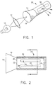
- a light integrator 20 having a central core 22 in the shape of a solid right cylinder, with opposed end faces 24 and 26 separated by elongated curved surface 28.
- Core 22 is made from any suitable light transmitting material such that light can be propagated down it by TIR, reflecting off curved surface 28. Particular materials include a glass, plastic, and more preferably, quartz or fused silica.
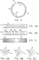
- An elongated scattering region 30 is provided on curved surface 28. Scattering region 30 is preferably a finely ground area on surface 28 which is parallel to the axis of core 22, and disrupts TIR inside core 22. Scattering region 30 has a stretched hourglass shape as best seen in FIG. 4A.
- Region 30 is slightly narrower toward end face 26 than toward the opposite end face 24.
- a reflective paint layer 32 is positioned immediately over (that is, contacting the surface of core 22 without any intervening layer) end 24 and all of curved surface 28, except a narrow elongated slit 34 parallel to the axis of core 22.
- End face 26 and slit 34 which are both regions of the core not covered by layer 32, define first and second light ports through which light can pass into or out of light integrator 20.
- a hollow cone 14 with a specular reflective inner surface is attached to end face 26, cone 14 having an end face 18 to receive light such that cone 14 directs it toward end face 26.
- cone 14 may be a solid optic cone (such as a glass cone), or a non-imaging optic such as described in High Collection Nonimaging Optics , by W.T. Welford and R. Winston, Academic Press, New York, 1989. It will be understood though, that cone 14 is not a part of the present light integrator invention and can even be omitted entirely in the use of the light integrator 20.
- reflective layer 32 have the required property of causing little or no disruption of TIR inside core 22.
- Such materials may be found among reflective materials of the type described above. Suitable materials are very readily determined using the test described above.
- suitable powdered materials which have the necessary properties when simply packed around the core include barium sulfate powder, table salt, granulated sugar and even powdered coffee whitener.
- the reflective layer be a painted layer 32 shown.
- the paint is a white powder in a carrier, and adheres to surface 28 when dry. It appears that the type and amount of carrier may affect whether the final dry layer has the necessary low effect on TIR, even if the packed powder material of the paint by itself may have.
- the proposed final layer should be tested for its effect on TIR in a manner such as described above since not all layers can be used.
- the following commercially available paints were found usuitable: three titanium compound containing paints, a zinc compound containing paint, a lead carbonate/zinc oxide paint, and a "KRYLON Flat While #1502" have not been found useful.
- Two particularly useful paints contain barium sulfate in a carrier, namely KODAK WHITE REFLECTANCE COATING available from Eastman Kodak Company, Rochester, NY, and SPECTRAFLECT available from Labsphere P.O. Box 70, North Sutton, NH 03260. Both of these paints contain barium sulfate in a carrier.
- the carrier includes alcohol/water/a small quantity of polyvinyl alcohol.
- packed powders of the type already described could be used.
- FIGS. 7A to 7C A particularly convenient method of manufacturing light integrator 20 is illustrated in FIGS. 7A to 7C.
- scattering region 30 is first finely ground on core 22.
- a mask 40 is then applied over end 26 and a mask 42 applied over surface 28 in the shape of the desired light port 34.
- the entire assembly can then be exposed to a paint which, when dry, will have the necessary reflective and low TIR affecting qualities.
- Masks 40 and 42 can then be removed and cone 14 positioned adjacent end face 26.
- An electrically powered light source 10 is positioned to direct light through a lens 12 and into face 18 of cone 14. Cone 14 concentrates the light by internal reflection and directs it into end face 26 (now acting as an entry light port) of core 22. The light then propagates down core 22 by TIR, reflecting off curved surface 28. Reflecting layer 32, being of the type described, does not substantially interrupt this TIR. Eventually light strikes scattering region 30 which disrupts its total internal reflection and diffusely scatters it. The resulting non-TIR light will then pass through curved surface 28, but be diffusely reflected repeatedly back into core 22 by reflective layer 32 until eventually exiting through slit 34 (which now acts as an exit light port).
- TIR Some fraction of the light propagating down the core by TIR reaches end face 24 before scattering, exits end face 24, reflects diffusely off reflective layer 32, and re-enters end face 24. As it re-enters, apparently because of the porosity of the reflective layer 32, the light refracts at end face 24 such that the diffusely reflected light becomes more collimated on re-entry, enhancing confinement in core 22 by TIR. This TIR light scatters, is reflected, and exits slit 34 in the same manner as above.
- the scattering region 30 With the shape of scattering region 30 shown in Figure 2 and 7A, light exiting slit 34 will be of fairly uniform intensity along the length and width of slit 34. However, different intensity profiles are readily achieved by altering the shape of scattering region 30. Also, instead of, or in addition to, controlling the shape of the scattering region, the scattering region can be duty cycle modulated by varying the frequency of occurrence and length of scattering portions 30a-30d which are along surface 28 of core 22, as shown in FIG. 4B.
- the scattering region can consist of a volume within the core 22 containing scattering centers such as illustrated in FIG. 5.
- the scattering centers can, for example, be voids or small particles.
- the density of scattering centers may be varied along the length of core 22, as shown in FIG. 5, to control the output profile.
- a variable which can be used to control the appearance of artifacts (particularly for a scanner application) as well as brightness, is the relative position or distance apart radially of slit 34 and scattering region 30 as shown in FIGS. 6A-6C.
- FIGS. 3 and 6B illustrate them spaced about 90° apart (note that in all of FIGS. 6A-6C reflective layer 32 is shown spaced apart from core 22 for clarity) and of approximately the same length and positions along core 22.
- Light which passes directly from scattering region 30 to slit 34 will tend to produce a peak in the angular profile of the output light exiting slit 34.
- scattering region 30 and slit 34 should be spaced less than 90° apart, such as a 0° orientation shown in FIG. 6A. The 180° separation tends to increase the brightness.
- light integrator 20 can be used in reverse from the manner described above as a light source, to provide a light collector.
- Fig. 8 illustrates a film scanner of the present invention using the light integrator arrangement shown in FIGS. 1-3 and 4A as a light source.
- An electric lamp light source 10 will be focused by a lens 12 onto face 18 as shown in FIG. 1 and described above.
- the diffuse light will leave through slit 34 and illuminate a film 70 held in place by a media holder (not shown) to receive light from slit 34.
- This illuminated stripe of film 70 is then imaged through a lens system 40 onto a linear sensor 50, such as a CCD array, which converts the scanned image into a sequence of signals corresponding to the image.
- a linear sensor 50 such as a CCD array
- FIG. 9 illustrates the use of light integrator 20 as a linear light collector used to collect a laser light beam passing through and modulated by the optical density of the image on a film 70 (again, held in place by a suitable media holder).
- film scanners may, for example, be used to scan radiographic images recorded by X-ray or the like on transparencies in order to provide a digital record for storage, transmission to remote locations and to conduct image enhancement and analysis.
- a laser light source 80 is imaged by a lens system 82 onto the facets of a rotating mirror 84 which deflects the beam in a scanning line onto the film 70.
- the scanned beam transverses the film 70, and the light transmitted through the film 70 enters the slit 34 of light integrator 20.
- Light integrator 20 functions inversely to its use as a linear light source described above. Light collected is directed to end face 26 which is covered by a light detector 60 which converts the signal received into a corresponding electrical output. In this manner each frame of film 70 can be converted to a sequence of signals corresponding to the image on it.
- the scanner of the present invention can have its media holder and other components positioned to scan a reflective medium (such as a photographic print) in a known manner.
- a reflective medium such as a photographic print
Applications Claiming Priority (2)
| Application Number | Priority Date | Filing Date | Title |
|---|---|---|---|
| US08/593,997 US5804818A (en) | 1996-01-30 | 1996-01-30 | Coated internally reflecting optical element |
| US593997 | 1996-01-30 |
Publications (2)
| Publication Number | Publication Date |
|---|---|
| EP0788000A2 true EP0788000A2 (de) | 1997-08-06 |
| EP0788000A3 EP0788000A3 (de) | 1997-10-29 |
Family
ID=24377091
Family Applications (1)
| Application Number | Title | Priority Date | Filing Date |
|---|---|---|---|
| EP97200089A Withdrawn EP0788000A3 (de) | 1996-01-30 | 1997-01-13 | Beschichtetes intern reflektierendes optisches Element |
Country Status (2)
| Country | Link |
|---|---|
| US (1) | US5804818A (de) |
| EP (1) | EP0788000A3 (de) |
Cited By (15)
| Publication number | Priority date | Publication date | Assignee | Title |
|---|---|---|---|---|
| EP0935091A1 (de) * | 1998-02-05 | 1999-08-11 | Hella KG Hueck & Co. | Stabförmiger Lichtleiter |
| EP1003321A2 (de) * | 1998-11-18 | 2000-05-24 | Bell & Howell Postal Systems Inc. | Integrierte Kammer mit Beleuchtungssystem |
| US6718189B2 (en) | 1995-08-09 | 2004-04-06 | Rio Grande Medical Technologies, Inc. | Method and apparatus for non-invasive blood analyte measurement with fluid compartment equilibration |
| US6816605B2 (en) | 1999-10-08 | 2004-11-09 | Lumidigm, Inc. | Methods and systems for biometric identification of individuals using linear optical spectroscopy |
| EP2180359A1 (de) * | 2008-10-27 | 2010-04-28 | Ushio Denki Kabushiki Kaisya | Beleuchtungsvorrichtung |
| US7890158B2 (en) | 2001-06-05 | 2011-02-15 | Lumidigm, Inc. | Apparatus and method of biometric determination using specialized optical spectroscopy systems |
| US8175346B2 (en) | 2006-07-19 | 2012-05-08 | Lumidigm, Inc. | Whole-hand multispectral biometric imaging |
| US8184873B2 (en) | 2003-04-04 | 2012-05-22 | Lumidigm, Inc. | White-light spectral biometric sensors |
| US8229185B2 (en) | 2004-06-01 | 2012-07-24 | Lumidigm, Inc. | Hygienic biometric sensors |
| US8285010B2 (en) | 2007-03-21 | 2012-10-09 | Lumidigm, Inc. | Biometrics based on locally consistent features |
| US8355545B2 (en) | 2007-04-10 | 2013-01-15 | Lumidigm, Inc. | Biometric detection using spatial, temporal, and/or spectral techniques |
| US8570149B2 (en) | 2010-03-16 | 2013-10-29 | Lumidigm, Inc. | Biometric imaging using an optical adaptive interface |
| US8781181B2 (en) | 2006-07-19 | 2014-07-15 | Lumidigm, Inc. | Contactless multispectral biometric capture |
| US8787630B2 (en) | 2004-08-11 | 2014-07-22 | Lumidigm, Inc. | Multispectral barcode imaging |
| GB2570779A (en) * | 2017-12-14 | 2019-08-07 | Schott Ag | Linear light source |
Families Citing this family (7)
| Publication number | Priority date | Publication date | Assignee | Title |
|---|---|---|---|---|
| US6274860B1 (en) * | 1999-05-28 | 2001-08-14 | Terrasun, Llc | Device for concentrating optical radiation |
| TW480456B (en) * | 2000-02-02 | 2002-03-21 | Umax Data Systems Inc | Circular optical reflection device |
| US6574490B2 (en) | 2001-04-11 | 2003-06-03 | Rio Grande Medical Technologies, Inc. | System for non-invasive measurement of glucose in humans |
| US7010012B2 (en) | 2001-07-26 | 2006-03-07 | Applied Optoelectronics, Inc. | Method and apparatus for reducing specular reflections in semiconductor lasers |
| US7746520B2 (en) * | 2004-11-23 | 2010-06-29 | Xerox Corporation | Document illuminator |
| US7593143B2 (en) * | 2005-03-31 | 2009-09-22 | Xerox Corporation | Compound curved concentrator based illuminator |
| US7715063B2 (en) * | 2005-03-31 | 2010-05-11 | Xerox Corporation | CVT integrated illuminator |
Citations (4)
| Publication number | Priority date | Publication date | Assignee | Title |
|---|---|---|---|---|
| US4205337A (en) | 1977-07-06 | 1980-05-27 | The Rank Organisation Limited | Television film scanner |
| US4797711A (en) | 1986-09-10 | 1989-01-10 | Dainippon Screen Mfg., Co., Ltd. | Image scanning apparatus |
| US5257340A (en) | 1992-06-01 | 1993-10-26 | Eastman Kodak Company | Linear coated core/clad light source/collector |
| US5274228A (en) | 1992-06-01 | 1993-12-28 | Eastman Kodak Company | Linear light source/collector with integrating cylinder and light pipe means |
Family Cites Families (5)
| Publication number | Priority date | Publication date | Assignee | Title |
|---|---|---|---|---|
| US4733332A (en) * | 1985-02-22 | 1988-03-22 | Agency Of Industrial Science And Technology | Illuminating device |
| US4768860A (en) * | 1985-09-21 | 1988-09-06 | Sumitomo Chemical Co., Ltd. | Plastic optical cable |
| US4835057A (en) * | 1987-03-25 | 1989-05-30 | At&T Bell Laboratories | Glass fibers having organosilsesquioxane coatings and claddings |
| US5241459A (en) * | 1992-06-01 | 1993-08-31 | Eastman Kodak Company | Integrating cylinder with end input illumination for use as an illuminator in a film scanner |
| US5672864A (en) * | 1996-02-26 | 1997-09-30 | Eastman Kodak Company | Light integrator |
-
1996
- 1996-01-30 US US08/593,997 patent/US5804818A/en not_active Expired - Lifetime
-
1997
- 1997-01-13 EP EP97200089A patent/EP0788000A3/de not_active Withdrawn
Patent Citations (4)
| Publication number | Priority date | Publication date | Assignee | Title |
|---|---|---|---|---|
| US4205337A (en) | 1977-07-06 | 1980-05-27 | The Rank Organisation Limited | Television film scanner |
| US4797711A (en) | 1986-09-10 | 1989-01-10 | Dainippon Screen Mfg., Co., Ltd. | Image scanning apparatus |
| US5257340A (en) | 1992-06-01 | 1993-10-26 | Eastman Kodak Company | Linear coated core/clad light source/collector |
| US5274228A (en) | 1992-06-01 | 1993-12-28 | Eastman Kodak Company | Linear light source/collector with integrating cylinder and light pipe means |
Non-Patent Citations (1)
| Title |
|---|
| WELFORD W.T., WINSTON R.: "High Collection Nonimaging Optics.", 1989, ACADEMIC PRESS., NEW YORK. |
Cited By (19)
| Publication number | Priority date | Publication date | Assignee | Title |
|---|---|---|---|---|
| US6718189B2 (en) | 1995-08-09 | 2004-04-06 | Rio Grande Medical Technologies, Inc. | Method and apparatus for non-invasive blood analyte measurement with fluid compartment equilibration |
| US9487398B2 (en) | 1997-06-09 | 2016-11-08 | Hid Global Corporation | Apparatus and method of biometric determination using specialized optical spectroscopy systems |
| EP0935091A1 (de) * | 1998-02-05 | 1999-08-11 | Hella KG Hueck & Co. | Stabförmiger Lichtleiter |
| EP1003321A2 (de) * | 1998-11-18 | 2000-05-24 | Bell & Howell Postal Systems Inc. | Integrierte Kammer mit Beleuchtungssystem |
| EP1003321A3 (de) * | 1998-11-18 | 2001-03-07 | Bell & Howell Postal Systems Inc. | Integrierte Kammer mit Beleuchtungssystem |
| US6816605B2 (en) | 1999-10-08 | 2004-11-09 | Lumidigm, Inc. | Methods and systems for biometric identification of individuals using linear optical spectroscopy |
| US7890158B2 (en) | 2001-06-05 | 2011-02-15 | Lumidigm, Inc. | Apparatus and method of biometric determination using specialized optical spectroscopy systems |
| US8184873B2 (en) | 2003-04-04 | 2012-05-22 | Lumidigm, Inc. | White-light spectral biometric sensors |
| US8229185B2 (en) | 2004-06-01 | 2012-07-24 | Lumidigm, Inc. | Hygienic biometric sensors |
| US8787630B2 (en) | 2004-08-11 | 2014-07-22 | Lumidigm, Inc. | Multispectral barcode imaging |
| US8175346B2 (en) | 2006-07-19 | 2012-05-08 | Lumidigm, Inc. | Whole-hand multispectral biometric imaging |
| US8781181B2 (en) | 2006-07-19 | 2014-07-15 | Lumidigm, Inc. | Contactless multispectral biometric capture |
| US8831297B2 (en) | 2006-07-19 | 2014-09-09 | Lumidigm, Inc. | Contactless multispectral biometric capture |
| US8285010B2 (en) | 2007-03-21 | 2012-10-09 | Lumidigm, Inc. | Biometrics based on locally consistent features |
| US8355545B2 (en) | 2007-04-10 | 2013-01-15 | Lumidigm, Inc. | Biometric detection using spatial, temporal, and/or spectral techniques |
| EP2180359A1 (de) * | 2008-10-27 | 2010-04-28 | Ushio Denki Kabushiki Kaisya | Beleuchtungsvorrichtung |
| US8570149B2 (en) | 2010-03-16 | 2013-10-29 | Lumidigm, Inc. | Biometric imaging using an optical adaptive interface |
| GB2570779A (en) * | 2017-12-14 | 2019-08-07 | Schott Ag | Linear light source |
| US10908342B2 (en) | 2017-12-14 | 2021-02-02 | Schott Ag | Linear light source |
Also Published As
| Publication number | Publication date |
|---|---|
| US5804818A (en) | 1998-09-08 |
| EP0788000A3 (de) | 1997-10-29 |
Similar Documents
| Publication | Publication Date | Title |
|---|---|---|
| US5804818A (en) | Coated internally reflecting optical element | |
| US5672864A (en) | Light integrator | |
| US4453180A (en) | Light pick-up device | |
| US5274228A (en) | Linear light source/collector with integrating cylinder and light pipe means | |
| US6724503B1 (en) | Image sensor substrate and image sensor employing it | |
| US5103385A (en) | Linear light source | |
| US3527535A (en) | Fingerprint observation and recording apparatus | |
| US5335158A (en) | High efficiency linear light source | |
| US4467195A (en) | Information detecting apparatus | |
| CA1188788A (en) | Light pick-up device | |
| EP0049048A1 (de) | Fluoreszenzbetätigter, räumliche Abtastung beantwortender Lichtempfänger | |
| US5257340A (en) | Linear coated core/clad light source/collector | |
| CA1209387A (en) | Light collection apparatus for a scanner | |
| US5598008A (en) | Wavelength selective light collector system | |
| US5774278A (en) | Spectral filter | |
| US6180955B1 (en) | Integrating optical collector with reduced re-illumination of phosphor sheet | |
| US5414489A (en) | Light pipe spectral filter | |
| US5256868A (en) | Contact scanners for scanning images of an illuminated film onto a photosensor array | |
| US5138161A (en) | Apparatus for reading radiation image information | |
| US4736099A (en) | Scan device with light mixer and diffusing means for half-tone transparency originals | |
| GB2299726A (en) | Diffusers for film scanners and the like | |
| JPH03117161A (ja) | 光学式原稿走査装置 | |
| EP0442699A2 (de) | Farbtrennungsabtaster | |
| US3837732A (en) | Partially transparent plates for increased image contrast | |
| JPS6165658A (ja) | 読取装置 |
Legal Events
| Date | Code | Title | Description |
|---|---|---|---|
| PUAI | Public reference made under article 153(3) epc to a published international application that has entered the european phase |
Free format text: ORIGINAL CODE: 0009012 |
|
| AK | Designated contracting states |
Kind code of ref document: A2 Designated state(s): DE FR GB |
|
| PUAL | Search report despatched |
Free format text: ORIGINAL CODE: 0009013 |
|
| AK | Designated contracting states |
Kind code of ref document: A3 Designated state(s): DE FR GB |
|
| 17P | Request for examination filed |
Effective date: 19980302 |
|
| 17Q | First examination report despatched |
Effective date: 20041006 |
|
| STAA | Information on the status of an ep patent application or granted ep patent |
Free format text: STATUS: THE APPLICATION HAS BEEN WITHDRAWN |
|
| 18W | Application withdrawn |
Effective date: 20060801 |