EP0787599B1 - Pneumatic tyre - Google Patents
Pneumatic tyre Download PDFInfo
- Publication number
- EP0787599B1 EP0787599B1 EP96309412A EP96309412A EP0787599B1 EP 0787599 B1 EP0787599 B1 EP 0787599B1 EP 96309412 A EP96309412 A EP 96309412A EP 96309412 A EP96309412 A EP 96309412A EP 0787599 B1 EP0787599 B1 EP 0787599B1
- Authority
- EP
- European Patent Office
- Prior art keywords
- parabola
- tyre
- axial
- circumferential
- grooves
- Prior art date
- Legal status (The legal status is an assumption and is not a legal conclusion. Google has not performed a legal analysis and makes no representation as to the accuracy of the status listed.)
- Expired - Lifetime
Links
Images


Classifications
-
- B—PERFORMING OPERATIONS; TRANSPORTING
- B60—VEHICLES IN GENERAL
- B60C—VEHICLE TYRES; TYRE INFLATION; TYRE CHANGING; CONNECTING VALVES TO INFLATABLE ELASTIC BODIES IN GENERAL; DEVICES OR ARRANGEMENTS RELATED TO TYRES
- B60C11/00—Tyre tread bands; Tread patterns; Anti-skid inserts
- B60C11/03—Tread patterns
- B60C11/0302—Tread patterns directional pattern, i.e. with main rolling direction
-
- B—PERFORMING OPERATIONS; TRANSPORTING
- B60—VEHICLES IN GENERAL
- B60C—VEHICLE TYRES; TYRE INFLATION; TYRE CHANGING; CONNECTING VALVES TO INFLATABLE ELASTIC BODIES IN GENERAL; DEVICES OR ARRANGEMENTS RELATED TO TYRES
- B60C11/00—Tyre tread bands; Tread patterns; Anti-skid inserts
- B60C11/03—Tread patterns
- B60C11/0304—Asymmetric patterns
-
- B—PERFORMING OPERATIONS; TRANSPORTING
- B60—VEHICLES IN GENERAL
- B60C—VEHICLE TYRES; TYRE INFLATION; TYRE CHANGING; CONNECTING VALVES TO INFLATABLE ELASTIC BODIES IN GENERAL; DEVICES OR ARRANGEMENTS RELATED TO TYRES
- B60C11/00—Tyre tread bands; Tread patterns; Anti-skid inserts
- B60C11/03—Tread patterns
- B60C11/0306—Patterns comprising block rows or discontinuous ribs
-
- B—PERFORMING OPERATIONS; TRANSPORTING
- B60—VEHICLES IN GENERAL
- B60C—VEHICLE TYRES; TYRE INFLATION; TYRE CHANGING; CONNECTING VALVES TO INFLATABLE ELASTIC BODIES IN GENERAL; DEVICES OR ARRANGEMENTS RELATED TO TYRES
- B60C11/00—Tyre tread bands; Tread patterns; Anti-skid inserts
- B60C11/03—Tread patterns
- B60C2011/0337—Tread patterns characterised by particular design features of the pattern
- B60C2011/0386—Continuous ribs
- B60C2011/0388—Continuous ribs provided at the equatorial plane
-
- Y—GENERAL TAGGING OF NEW TECHNOLOGICAL DEVELOPMENTS; GENERAL TAGGING OF CROSS-SECTIONAL TECHNOLOGIES SPANNING OVER SEVERAL SECTIONS OF THE IPC; TECHNICAL SUBJECTS COVERED BY FORMER USPC CROSS-REFERENCE ART COLLECTIONS [XRACs] AND DIGESTS
- Y10—TECHNICAL SUBJECTS COVERED BY FORMER USPC
- Y10S—TECHNICAL SUBJECTS COVERED BY FORMER USPC CROSS-REFERENCE ART COLLECTIONS [XRACs] AND DIGESTS
- Y10S152/00—Resilient tires and wheels
- Y10S152/03—Slits in threads
Definitions
- the present invention relates to a pneumatic tyre having an improved tread portion provided with parabolic grooves to improve wet performance of the tyre.
- tread patterns comprising circumferential and axial grooves to define blocks are widely used to provide good wet performance.
- the number and/or width of the circumferential and axial grooves has increased and/or the land/sea ratio of the tread has been decreased.
- an object of the present invention to provide a pneumatic tyre in which the flow of water is improved and at the same time the flow of air is improved to improve the wet performance without increasing tyre noise.
- a tire according to the preamble of claim 1 is known by e.g. GB-A-1 499 365.
- a pneumatic tyre comprises, a tread portion having a tread surface having tread edges, a pair of circumferential grooves one disposed on each side of the tyre equator and near the tyre equator and extending continuously in the circumferential direction of the tyre so as to define a central part between the circumferential grooves and a pair of axially outer parts axially outward of the circumferential grooves, and axial grooves disposed in each of the axially outer parts at pitches P in the tyre circumferential direction, and each of the axial grooves extending from one of the circumferential grooves to one of the tread edges along a parabola, and the parabola axis extending parallel to the tyre axial direction, and the parabola focus disposed axially outward of the parabola vertex, wherein the parabola has a vertex disposed on the axially outer edge of the circumferential groove, and the axial groove
- the flow of air is also smooth and tyre noise especially pumping noise is effectively decreased, and as a result resonance noise is also decreased.
- the edges are prevented from simultaneously contacting the ground, and as a result the so called impact sound is decreased, which also reduces the tyre noise.
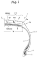
- Fig. 1 shows a pneumatic tyre 1 according to the invention which is a low aspect ratio radial tyre for passenger cars, and an example of the internal tyre structure is shown.
- the tyre 1 comprises a tread portion 2, a pair of sidewall portions 3, a pair of axially spaced bead portions 4 each provided with a bead core 5 therein, a radial carcass 6 extending between the bead portions 4 through the tread portion 2 and sidewall portions 3 and turned up around the bead cores 5 to be secured thereto, and a stiff belt 7 disposed, as a hoop, radially outside the carcass 6 and inside the tread portion 2.
- a pair of circumferential grooves 9L and 9R (generically 9) and axial grooves 10L and 10R (generically 10) are disposed to form novel tread patterns shown in Figs. 2-5.
- the circumferential grooves 9L and 9R are disposed one on each side (left side and right side) of the tyre equator C and near the tyre equator C. They extend continuously in the circumferential direction of the tyre so as to define a central part of the tread between the circumferential grooves 9L and 9R and a pair of axially outer parts 2L and 2R of the tread each extending from the axially outer edge 9e of one of the circumferential grooves 9L, 9R to one of the tread edges Te.
- the axial grooves 10L and 10R are arranged circumferentially at regular or irregular pitches and connected with the circumferential grooves 9L and 9R, respectively.
- Each axial groove 10 extends as a parabola 12 from one of the circumferential grooves 9 to beyond one of the tread edges Te so that the axially inner end is opened to the circumferential groove 9 and the axially outer end is opened in a buttress portion 15.
- the tread edges Te are each defined as the axial outermost edge of the ground contacting region of the tread portion 2 under the condition when the tyre is mounted on its standard rim, inflated to its normal pressure and then loaded with 80 % of the maximum load.
- the standard rim is a rim officially approved for the tyre by, for example JATMA (Japan), TRA (USA), ETRTO (Europe) and the like, and the normal pressure and maximum load are officially specified by the same associations.
- the tread width TW is defined between the tread edges Te.
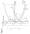
- This equation is expressed, based on X-Y coordinates in which the X-axis extends parallel to the tyre circumferential direction, the Y-axis extends parallel to the tyre axial direction, the origin O is set at a small axial distance H1 from the tyre equator C, the unit length H2 in the Y-axis is equal to one tenth of the axial distance between the origin O and tread edge Te, the unit length H3 in the X-axis is equal to one tenth of a pitch P.
- the vertex of the parabola is at the origin O, and the parabola axis extends parallel to the tyre axial direction.
- the direction of the parabola is such that the focus is axially outside the origin O.
- a plurality of parabolas 12 are described on each side of the tyre equator C, setting the origins O thereof on a circumferential line 14 at pitches P.
- the pitches P it is possible to use regular pitches or variable pitches.
- the above-mentioned unit length H3 on one side of the parabola axis may be different to the other side. Accordingly, the parabola 12 always intersects the circumferentially adjacent parabolas 12 at points K which are (+5, 25A) and (-5, 25A).
- the pitches of the axial grooves 10 are defined by the pitches P.
- the number of pitches P per circumference is in the range of from 40 to 80 in case of passenger car tyres.
- a part of the tread which extends axially inwardly from the above-mentioned circumferential straight line 14 by an axial distance W1 is engraved as the circumferential groove 9.
- a generally triangular part (O-K-O) surrounded by the circumferential straight line 14 and two adjacent parabolas 12 is engraved as a flaring junction part 17 between the circumferential groove 9 and axial groove 10. No step difference is formed in the depth of the channel from the circumferential groove 9 to the axial groove 10 through the flaring junction part 17, but a gradual change may be possible.
- the circumferential groove 9 is regarded as having an axially outer edge which has a wavy configuration.
- the axially inner edge of the circumferential groove 9 preferably has a generally straight configuration.
- the central part of the tread is formed as a circumferentially continuously extending straight rib.
- the axial distance H1 from the tyre equator C to the line 14 is set in the range of from 0.05 to 0.20 times the tread width TW.
- the axial distance W1 is set in the range of from 0.03 to 0.10 times the tread width TW.
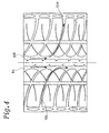
- one axial groove 10 is formed on one side of the parabola axis, and on the other side of the parabola axis one sipe 16 is formed along the parabola.
- the axial grooves 10 are formed on the same side of the parabola axes.
- a sipe is a cut or narrow groove having a width of from 0 to 2 mm.
- the blocks 18 defined between the axial grooves 10 increase the pattern rigidity in the tyre axial direction to increase the cornering force and thus cornering performance in dry conditions can be improved.
- the sipes 16 can display their edge effect to improve wet performance especially wet road grip without decreasing the pattern rigidity.
- each sipe 16 is terminated in the block 18 to maintain the pattern rigidity at a high level.
- Each of the axial grooves 10 is formed on the other side of the parabola 12 than the same side as the focus, placing an axially outer groove wall 13A on the parabola 12 and an axially inner groove wall 13B extending substantially parallel thereto on the outside of the parabola. Accordingly, a convexly curved groove edge or groove wall which extends from a parabola vertex to the tread edge is formed.
- the groove width W2 of the axial grooves 10 is set to be not more than the axial distance W1 but more than the width of the sipe.
- the axial grooves 10R on the right side of the tyre equator C are formed on the lower side Re of the parabola axes, but the axial grooves 10L on the left side are formed on the upper side Fr to form a tread pattern which has substantially point symmetry.
- tread portion 2 in this example is provided with two circumferential grooves 11L and 11R each disposed in the middle of each of the axially outer parts 2L and 2R and extending continuously in the tyre circumferential direction in addition to the above-mentioned pair of circumferential grooves 9L and 9R.
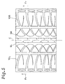
- Fig. 5 shows a modification of the above-mentioned tread pattern, wherein the axial grooves 10R on one (right) side of the tyre equator C are formed on the upper side Fr of the parabola axes, and the axial grooves 10L on the other (left) side are also formed on the same upper side Fr, thereby forming a tread pattern which is substantially a line symmetry about the tyre equator C, but the pattern is otherwise the same as the former example.
- Test tyres in size of 195/65R15 having the internal structure shown in Fig. 1 were made and tested for wet performance and noise.
- the example tyre had the tread pattern shown in Fig. 2, but the reference tyre had the tread pattern shown in Fig. 6.
- lateral-G was measured on a wet track to measure the wet performance.
- the test car was run in a 100 m radius curved course on a paved road surface provided with a 5 mm depth 20 m long water pool, and the lateral-G was measured in the speed range of from 70 to 90 km/h to calculate the average lateral-G in this speed range. Further, the maximum lateral-G was measured.
Description
| Tyre | Ex. | Ref. |
| Tread pattern | Fig. 2 | Fig. 6 |
| Land/sea (%) | 68.8 | 68.4 |
| Noise | ||
| under 30 km/h | 6 | 6 |
| 30 to 60 km/h | 6 | 6 |
| 60 to 90 km/h | 7 | 6 |
| over 90 km/h | 6 | 6 |
| Wet performance | ||
| Maximum lateral G | 0.34 | 0.306 |
| Average lateral G | 0.286 | 0.239 |
Claims (6)
- A pneumatic tyre (1) comprising, a tread portion (2) having a tread surface having tread edges (Te), a pair of circumferential grooves (9) one disposed on each side of the tyre equator (C) and near the tyre equator (C) and extending continuously in the circumferential direction of the tyre (1) so as to define a central part between the circumferential grooves and a pair of axially outer parts (2L and 2R) axially outward of the circumferential grooves, and axial grooves (10) disposed in each of the axially outer parts (2L and 2R) at pitches P in the tyre circumferential direction, each of the axial grooves (10) extending from one of the circumferential grooves (9L, 9R) to one of the tread edges (Te) along a parabola (12), and the parabola axis (Y) extending parallel to the tyre axial direction, and the parabola focus disposed axially outward of the parabola vertex (O), characterised in that the parabola (12) has a vertex (O) disposed on the axially outer edge (9e) of the circumferential groove, and the axial groove (10) has an axially outer edge (13A) extending on the parabola (12) from the parabola vertex (O) to the tread edge.
- A pneumatic tyre according to claim 1, characterised in that each said parabola (12) is described according to an equation
- A pneumatic tyre according to claim 1 or 2, characterised in that a generally triangular part (O-K-O) surrounded by the circumferentially adjacent parabolas (12) and a circumferential straight line (14) drawn between the parabola vertexes thereof is engraved to form a flaring junction part (17) between the circumferential groove (9) and axial groove (10).
- A pneumatic tyre according to any of claims 1 to 3, characterised in that with respect to each said parabola (12), one axial groove (10) is formed on one side of the parabola axis (Y).
- A pneumatic tyre according to claim 4, characterised in that on the other side of the parabola axis (Y), a sipe (16) is disposed to extend along the parabola.
- A pneumatic tyre according to claim 4, characterised in that on one side of the tyre equator (C), the axial grooves (10) are formed on the same one side of the parabola axes (Y), but on the other side of the tyre equator, the axial grooves (10) are formed on the same other side of the parabola axes (Y).
Applications Claiming Priority (3)
| Application Number | Priority Date | Filing Date | Title |
|---|---|---|---|
| JP14460/96 | 1996-01-30 | ||
| JP8014460A JP2934405B2 (en) | 1996-01-30 | 1996-01-30 | Pneumatic tire |
| JP1446096 | 1996-01-30 |
Publications (2)
| Publication Number | Publication Date |
|---|---|
| EP0787599A1 EP0787599A1 (en) | 1997-08-06 |
| EP0787599B1 true EP0787599B1 (en) | 2000-02-09 |
Family
ID=11861669
Family Applications (1)
| Application Number | Title | Priority Date | Filing Date |
|---|---|---|---|
| EP96309412A Expired - Lifetime EP0787599B1 (en) | 1996-01-30 | 1996-12-23 | Pneumatic tyre |
Country Status (4)
| Country | Link |
|---|---|
| US (1) | US5851322A (en) |
| EP (1) | EP0787599B1 (en) |
| JP (1) | JP2934405B2 (en) |
| DE (1) | DE69606618T2 (en) |
Families Citing this family (20)
| Publication number | Priority date | Publication date | Assignee | Title |
|---|---|---|---|---|
| DE19708612A1 (en) * | 1997-03-03 | 1998-09-10 | Sp Reifenwerke Gmbh | Vehicle tires |
| US6412531B1 (en) * | 1999-07-15 | 2002-07-02 | Michelin Recherche Et Technique S.A. | Tire tread having groove walls with compound contours |
| JP3367927B2 (en) * | 2000-01-24 | 2003-01-20 | 住友ゴム工業株式会社 | Pneumatic tire |
| WO2002078982A1 (en) * | 2001-03-30 | 2002-10-10 | Pirelli Pneumatici S.P.A. | Tread pattern for car tire |
| US6631746B2 (en) * | 2001-04-25 | 2003-10-14 | Bridgestone/Firestone North American Tire, Llc | Undercut tie bar for pneumatic tire |
| US7270162B2 (en) * | 2004-07-21 | 2007-09-18 | The Yokohama Rubber Co. Ltd. | Pneumatic tire with tread surface having blocks with sipes forming meandrous shape |
| JP4869089B2 (en) * | 2007-01-22 | 2012-02-01 | 株式会社ブリヂストン | Pneumatic tire |
| JP5014840B2 (en) * | 2007-03-06 | 2012-08-29 | 東洋ゴム工業株式会社 | Pneumatic tire manufacturing method and pneumatic tire |
| US7950426B2 (en) * | 2007-06-08 | 2011-05-31 | Bridgestone Americas Tire Operations, Llc | Tread blocks having reduced edge stiffness |
| JP4394161B1 (en) * | 2009-04-17 | 2010-01-06 | 横浜ゴム株式会社 | Pneumatic tire |
| CN102770286B (en) * | 2010-02-26 | 2015-12-16 | 株式会社普利司通 | Air-inflation tyre |
| JP5461233B2 (en) * | 2010-02-26 | 2014-04-02 | 株式会社ブリヂストン | Pneumatic tire |
| JP5419752B2 (en) * | 2010-02-26 | 2014-02-19 | 株式会社ブリヂストン | Pneumatic tire |
| US20140034200A1 (en) * | 2012-07-31 | 2014-02-06 | Bridgestone Americas Tire Operations, Llc | Tire with laminate |
| US11260697B2 (en) * | 2014-12-04 | 2022-03-01 | Bridgestone Americas Tire Operations, Llc | Tire with tread features having offset protrusions |
| JP6393208B2 (en) * | 2015-02-16 | 2018-09-19 | 住友ゴム工業株式会社 | Pneumatic tire |
| JP6750358B2 (en) * | 2016-07-11 | 2020-09-02 | 住友ゴム工業株式会社 | Pneumatic tire |
| US20190061433A1 (en) * | 2017-08-23 | 2019-02-28 | The Goodyear Tire & Rubber Company | Tread for a pneumatic tire |
| JP7135331B2 (en) * | 2018-02-14 | 2022-09-13 | 横浜ゴム株式会社 | pneumatic tire |
| JP2022067497A (en) * | 2020-10-20 | 2022-05-06 | 住友ゴム工業株式会社 | tire |
Family Cites Families (12)
| Publication number | Priority date | Publication date | Assignee | Title |
|---|---|---|---|---|
| DE2455130A1 (en) * | 1974-11-21 | 1976-05-26 | Continental Gummi Werke Ag | PNEUMATIC TIRES FOR MOTOR VEHICLES |
| US4424845A (en) * | 1982-03-17 | 1984-01-10 | The Goodyear Tire & Rubber Company | Pneumatic tire tread |
| US4424844A (en) * | 1982-03-17 | 1984-01-10 | The Goodyear Tire & Rubber Company | Tire tread |
| US4424843A (en) * | 1982-03-17 | 1984-01-10 | The Goodyear Tire & Rubber Company | Pneumatic tire tread |
| US4865098A (en) * | 1983-02-09 | 1989-09-12 | The Goodyear Tire & Rubber Company | Pneumatic aircaft tire |
| DE3478675D1 (en) * | 1984-08-28 | 1989-07-20 | Goodyear Tire & Rubber | Pneumatic tires |
| JPH0284701U (en) * | 1988-12-21 | 1990-07-02 | ||
| JP2755995B2 (en) * | 1989-06-07 | 1998-05-25 | 株式会社ブリヂストン | Pneumatic tire |
| JP3062312B2 (en) * | 1991-09-10 | 2000-07-10 | オーツタイヤ株式会社 | Pneumatic tire |
| JPH05178023A (en) * | 1991-12-27 | 1993-07-20 | Yokohama Rubber Co Ltd:The | Pneumatic tire |
| USD344697S (en) | 1992-08-24 | 1994-03-01 | The Goodyear Tire & Rubber Company | Tire tread |
| DE4239475A1 (en) * | 1992-11-25 | 1994-05-26 | Continental Ag | Tyre tread with minimal aquaplaning - has sets of longer and shorter arc-shaped grooves running at acute angle from and back to edge, meeting edges at different points |
-
1996
- 1996-01-30 JP JP8014460A patent/JP2934405B2/en not_active Expired - Fee Related
- 1996-12-23 DE DE69606618T patent/DE69606618T2/en not_active Expired - Fee Related
- 1996-12-23 EP EP96309412A patent/EP0787599B1/en not_active Expired - Lifetime
- 1996-12-30 US US08/774,640 patent/US5851322A/en not_active Expired - Fee Related
Also Published As
| Publication number | Publication date |
|---|---|
| JP2934405B2 (en) | 1999-08-16 |
| DE69606618D1 (en) | 2000-03-16 |
| US5851322A (en) | 1998-12-22 |
| JPH09207521A (en) | 1997-08-12 |
| DE69606618T2 (en) | 2000-06-08 |
| EP0787599A1 (en) | 1997-08-06 |
Similar Documents
| Publication | Publication Date | Title |
|---|---|---|
| EP0787599B1 (en) | Pneumatic tyre | |
| US10752057B2 (en) | Pneumatic tire | |
| EP3025874B1 (en) | Pneumatic tire | |
| US6340040B1 (en) | Vehicle tire including main grooves and lug grooves | |
| US9457622B2 (en) | Pneumatic tire | |
| EP3015286B1 (en) | Pneumatic tire | |
| US8210219B2 (en) | Pneumatic tire with tread having crown rib and middle ribs | |
| US9950572B2 (en) | Pneumatic tire | |
| US8640750B2 (en) | Pneumatic tire with tread having shoulder blocks and crown blocks | |
| US6626215B2 (en) | Pneumatic tire including long and narrow blocks with at least two sipes | |
| EP0508090B1 (en) | Pneumatic tire having a unique footprint | |
| US9302548B2 (en) | Pneumatic tire | |
| US6105644A (en) | Pneumatic tire including three asymmetrically arranged main grooves | |
| EP0648622B1 (en) | Pneumatic tyre | |
| EP0688685B1 (en) | Pneumatic Tires | |
| EP1437237A2 (en) | Pneumatic tire | |
| EP2239153A1 (en) | Pneumatic tire | |
| EP0812708B1 (en) | Pneumatic radial tires | |
| EP0858916B1 (en) | Vehicle tyre | |
| US5837074A (en) | Pneumatic tire | |
| EP0728599B1 (en) | Pneumatic tyre | |
| EP0661182B1 (en) | Pneumatic tyre | |
| US6164354A (en) | Pneumatic tire | |
| EP0676305B1 (en) | Pneumatic tyre | |
| AU2004202040A1 (en) | Pneumatic Tire |
Legal Events
| Date | Code | Title | Description |
|---|---|---|---|
| PUAI | Public reference made under article 153(3) epc to a published international application that has entered the european phase |
Free format text: ORIGINAL CODE: 0009012 |
|
| AK | Designated contracting states |
Kind code of ref document: A1 Designated state(s): DE FR GB |
|
| 17P | Request for examination filed |
Effective date: 19971007 |
|
| GRAG | Despatch of communication of intention to grant |
Free format text: ORIGINAL CODE: EPIDOS AGRA |
|
| 17Q | First examination report despatched |
Effective date: 19990215 |
|
| GRAG | Despatch of communication of intention to grant |
Free format text: ORIGINAL CODE: EPIDOS AGRA |
|
| GRAH | Despatch of communication of intention to grant a patent |
Free format text: ORIGINAL CODE: EPIDOS IGRA |
|
| GRAH | Despatch of communication of intention to grant a patent |
Free format text: ORIGINAL CODE: EPIDOS IGRA |
|
| GRAA | (expected) grant |
Free format text: ORIGINAL CODE: 0009210 |
|
| AK | Designated contracting states |
Kind code of ref document: B1 Designated state(s): DE FR GB |
|
| REF | Corresponds to: |
Ref document number: 69606618 Country of ref document: DE Date of ref document: 20000316 |
|
| ET | Fr: translation filed | ||
| PLBE | No opposition filed within time limit |
Free format text: ORIGINAL CODE: 0009261 |
|
| STAA | Information on the status of an ep patent application or granted ep patent |
Free format text: STATUS: NO OPPOSITION FILED WITHIN TIME LIMIT |
|
| 26N | No opposition filed | ||
| REG | Reference to a national code |
Ref country code: GB Ref legal event code: IF02 |
|
| PGFP | Annual fee paid to national office [announced via postgrant information from national office to epo] |
Ref country code: FR Payment date: 20051208 Year of fee payment: 10 |
|
| PGFP | Annual fee paid to national office [announced via postgrant information from national office to epo] |
Ref country code: DE Payment date: 20051215 Year of fee payment: 10 |
|
| PGFP | Annual fee paid to national office [announced via postgrant information from national office to epo] |
Ref country code: GB Payment date: 20051221 Year of fee payment: 10 |
|
| PG25 | Lapsed in a contracting state [announced via postgrant information from national office to epo] |
Ref country code: DE Free format text: LAPSE BECAUSE OF NON-PAYMENT OF DUE FEES Effective date: 20070703 |
|
| GBPC | Gb: european patent ceased through non-payment of renewal fee |
Effective date: 20061223 |
|
| REG | Reference to a national code |
Ref country code: FR Ref legal event code: ST Effective date: 20070831 |
|
| PG25 | Lapsed in a contracting state [announced via postgrant information from national office to epo] |
Ref country code: GB Free format text: LAPSE BECAUSE OF NON-PAYMENT OF DUE FEES Effective date: 20061223 |
|
| PG25 | Lapsed in a contracting state [announced via postgrant information from national office to epo] |
Ref country code: FR Free format text: LAPSE BECAUSE OF NON-PAYMENT OF DUE FEES Effective date: 20070102 |