EP0787370B1 - Protector for one or more electromagnetic sensors - Google Patents
Protector for one or more electromagnetic sensors Download PDFInfo
- Publication number
- EP0787370B1 EP0787370B1 EP96925227A EP96925227A EP0787370B1 EP 0787370 B1 EP0787370 B1 EP 0787370B1 EP 96925227 A EP96925227 A EP 96925227A EP 96925227 A EP96925227 A EP 96925227A EP 0787370 B1 EP0787370 B1 EP 0787370B1
- Authority
- EP
- European Patent Office
- Prior art keywords
- frequency
- electromagnetic
- layer
- transmission
- layers
- Prior art date
- Legal status (The legal status is an assumption and is not a legal conclusion. Google has not performed a legal analysis and makes no representation as to the accuracy of the status listed.)
- Expired - Lifetime
Links
- 230000001012 protector Effects 0.000 title description 2
- 230000005540 biological transmission Effects 0.000 claims description 44
- 230000000737 periodic effect Effects 0.000 claims description 31
- 230000005670 electromagnetic radiation Effects 0.000 claims description 17
- 238000010276 construction Methods 0.000 description 8
- 230000005855 radiation Effects 0.000 description 8
- 238000010586 diagram Methods 0.000 description 5
- 230000001681 protective effect Effects 0.000 description 5
- 238000012856 packing Methods 0.000 description 4
- 230000001066 destructive effect Effects 0.000 description 3
- 238000000034 method Methods 0.000 description 3
- 239000004020 conductor Substances 0.000 description 2
- 230000001419 dependent effect Effects 0.000 description 2
- 230000002452 interceptive effect Effects 0.000 description 2
- 238000003754 machining Methods 0.000 description 2
- 238000004519 manufacturing process Methods 0.000 description 2
- RYGMFSIKBFXOCR-UHFFFAOYSA-N Copper Chemical compound [Cu] RYGMFSIKBFXOCR-UHFFFAOYSA-N 0.000 description 1
- 229920000271 Kevlar® Polymers 0.000 description 1
- 239000004411 aluminium Substances 0.000 description 1
- XAGFODPZIPBFFR-UHFFFAOYSA-N aluminium Chemical compound [Al] XAGFODPZIPBFFR-UHFFFAOYSA-N 0.000 description 1
- 229910052782 aluminium Inorganic materials 0.000 description 1
- 230000000295 complement effect Effects 0.000 description 1
- 239000010949 copper Substances 0.000 description 1
- 229910052802 copper Inorganic materials 0.000 description 1
- 230000008878 coupling Effects 0.000 description 1
- 238000010168 coupling process Methods 0.000 description 1
- 238000005859 coupling reaction Methods 0.000 description 1
- 238000005516 engineering process Methods 0.000 description 1
- 239000003365 glass fiber Substances 0.000 description 1
- 239000004761 kevlar Substances 0.000 description 1
- 239000000463 material Substances 0.000 description 1
- 239000011148 porous material Substances 0.000 description 1
- 239000004065 semiconductor Substances 0.000 description 1
- 230000035945 sensitivity Effects 0.000 description 1
- 239000000758 substrate Substances 0.000 description 1
- 230000001629 suppression Effects 0.000 description 1
- 229920001169 thermoplastic Polymers 0.000 description 1
- 239000004416 thermosoftening plastic Substances 0.000 description 1
Images


Classifications
-
- H—ELECTRICITY
- H01—ELECTRIC ELEMENTS
- H01Q—ANTENNAS, i.e. RADIO AERIALS
- H01Q15/00—Devices for reflection, refraction, diffraction or polarisation of waves radiated from an antenna, e.g. quasi-optical devices
- H01Q15/0006—Devices acting selectively as reflecting surface, as diffracting or as refracting device, e.g. frequency filtering or angular spatial filtering devices
- H01Q15/0013—Devices acting selectively as reflecting surface, as diffracting or as refracting device, e.g. frequency filtering or angular spatial filtering devices said selective devices working as frequency-selective reflecting surfaces, e.g. FSS, dichroic plates, surfaces being partly transmissive and reflective
-
- H—ELECTRICITY
- H01—ELECTRIC ELEMENTS
- H01Q—ANTENNAS, i.e. RADIO AERIALS
- H01Q1/00—Details of, or arrangements associated with, antennas
- H01Q1/42—Housings not intimately mechanically associated with radiating elements, e.g. radome
- H01Q1/421—Means for correcting aberrations introduced by a radome
Definitions
- the present invention relates to an arrangement for protecting (shielding) one or more electromagnetic sensors against undesirable electromagnetic radiation.
- An object's radar signature is the object's three-dimensional electromagnetic radiation diagram which is obtained from it being irradiated with electromagnetic signals of differing frequencies and from the object's self-produced electromagnetic radiation.
- An object's radar signature can also be seen as a diagram of the object's equivalent reflection surface in three dimensions, which of course only gives a picture of the radar signature for incident radiation.
- periodic patterns consisting of aperture elements can be used, for example slits which, simply expressed, are holes of some form in an electrically-conductive plane, or periodic patterns can be used which consist of electrically-conductive elements, for example dipoles or printed conductive elements, which can be described as electrically-conductive islands in some form on an insulated plane. These two types of periodic pattern give rise to surfaces with different frequency behaviour.
- the surface transmits at the aperture elements' resonant frequency f 0 .
- This means that the surface will have a transmission window (compare with pass-band filters) where the maximum transmission through the surface is obtained at a frequency which is determined by the elements' resonant frequency with a wavelength ⁇ (element length ⁇ ⁇ /2 ⁇ ⁇ electrical wavelength ⁇ ) .
- the surface will reflect at the elements' resonant frequency. That means that the surface will have a reflection window (compare with suppression/stop-band filters) where the maximum reflection is obtained at a frequency which is determined by the elements' resonant frequency (element length ⁇ ⁇ /2).
- a frequency-selective surface/radome is a periodic pattern with aperture elements.
- Such a surface has a transmission window, i.e. it is transparent for a chosen frequency range.
- the characteristics of the radome can be additionally improved/altered, i.e. full transmission at a desired transmission frequency can be obtained, as well as steeper flanks in the window.
- the frequency of the radiation at which the grating lobes occur depends on the packing density of the periodic pattern. If the elements lie more sparsely than ⁇ /2, grating lobes occur in the radome's radar signature. That means that the grating lobes will occur for electromagnetic radiation with a wavelength ⁇ which is less than two times the distance between the elements.
- the electromagnetic protection (shielding) which the FSS-radome gives to the sensor is limited.
- the sensor is electromagnetically unprotected at frequencies which are multiples of the sensor's own frequency and additionally the sensor's radar signature is worsened in that the grating lobes, which were perhaps not present previously, may be introduced at the sensor's own frequency or near to it.
- the electromagnetic protection which the radome provides is for incident radiation with frequencies lower than the sensor's own frequency, for these frequencies the FSS-surface appears approximately as a purely metallic surface.
- the method of using a periodic aperture pattern in a frequency-selective surface/radome is described in published articles.
- the method of combining a plurality of layers of similar pattern in order to obtain different characteristics in the FSS-surfaces is also described.
- US patent no. 5 208 603 discloses a solution, in which an outer layer consisting of periodic patterns of apertures is combined with an inner interposed layer consisting of a periodic pattern of conductive elements.
- the purpose according to the patent is to obtain a compact radome solution which transmits at two frequencies.
- the purpose of the middle layer consisting of conductive elements is to achieve a coupling between the aperture layers, which thereby allows transmission at two frequencies.
- the described solution does not solve the problem of the radome being open to multiple frequencies of the undesired transmission frequencies.
- the construction allows a denser packing of the elements than with a conventional solution, which means that the grating lobes can be avoided at f 0 .
- the layer which is the interface to the surroundings consists of apertures and is resonant for an undesired transmission frequency f 0 , the packing density of the apertures will however be such that the grating lobes will occur from about 2f 0 .
- One object of the invention is to define a frequency-selective arrangement/surface which allows transmission of, i.e. is transparent to, incident and emitted electromagnetic radiation at one or more predetermined frequencies.
- Another object of the invention is to define a frequency-selective arrangement which solves the problems with the occurrence of grating lobes around the desired transmission frequency/frequencies.
- a still further object of the invention is to define a frequency-selective arrangement which allows transmission of electromagnetic radiation at one or more frequencies and prevents transmission at multiples of the transmission frequency/frequencies.
- An additional object of the invention is to define a frequency-selective arrangement for one or more sensors and/or sending and/or receiving antennas (an antenna arrangement or antenna arrangements), which allows control of, and/or a reduction of, their radar signature.
- the aforementioned objects are achieved in accordance with the invention by a frequency-selective surface/arrangement designed to transmit (allow to pass through) electromagnetic radiation around one or more predetermined transmission frequencies.
- the frequency-selective arrangement/surface comprises a plurality of layers, having at least one outer electromagnetic reflecting layer and one inner electromagnetic transmitting layer.
- the outer layer is positioned closer to the surroundings than the inner layer.
- the inner layer is positioned closer than the outer layer to the antenna arrangement(s) that the frequency-selective arrangement is placed in front of, in order to be a frequency-selective arrangement for the antenna arrangement(s).
- the outer layer comprises at least one electromagnetic reflecting layer where each reflecting layer comprises periodic patterns of electrically conductive elements.
- Each periodic pattern of electrically conductive elements is arranged to possess a reflection resonance frequency for electromagnetic radiation which is higher than the transmission frequency, preferably of the order of three times larger.
- the frequency-selective surface's/arrangement's inner layer is placed at a predetermined distance from the outer layer, said distance being chosen dependent upon which characteristics the radome should have.
- the inner layer comprises at least one electromagnetic transmitting layer where each transmitting layer comprises a periodic pattern of aperture elements. Each periodic pattern of aperture elements is arranged to possess a transmission resonance frequency for electromagnetic radiation which is substantially the same as the transmission frequency.
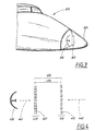
- Figure 1 shows an electromagnetic sensor/antenna 110 which is mechanically protected behind a radome 120.
- the radome 120 is suitably electromagnetically transparent, mechanically stable so as to provide an aerodynamic protective casing in, for instance, the nose of an aeroplane 100 and aerodynamically adapted to the rest of the fuselage.
- the sensitivity of the sensors has also increased both for the actual desired signal and for powerful destructive radiation.
- various protective circuits are most often optimised to operate best around, for instance, a radar's transmitting frequency due to the fact that the protective circuits are primarily there to protect the receiver circuits from powerful radiation during transmission from its own transmitter.
- One way of constructing a frequency-selective surface is to use a periodic pattern (see figure 2) consisting of slits 210 or dipoles. With the construction of frequency-selective radomes, the most common way is with one or more layers of slits (aperture elements). This/these layer(s) can be constructed into a radome 120 according to figure 1 in order, thereby, to also create a certain electromagnetic protection.
- a frequency-selective surface 322 is separate from an outer radome 324 in front of a sensor/antenna 310, in order for example to form the frequency-selective surface 322 as a corner reflector so as to increase and obtain an equivalent reflection surface which is several times larger than the geometrical surface. It can be valuable for commercial aeroplanes 300 to be electromagnetically clearly visible, i.e. with radar, but less desirable in other connections. If it desired not to be electromagnetically visible, the frequency-selective surface 322 in figure 3 or the radome 120 in figure 1 (with a frequency-selective layer) can be geometrically formed in order to minimise their equivalent reflection surfaces.
- a controllable and predictable radar signature by means of, for example, a special geometrical form of a radome with a frequency-selective surface or only one frequency-selective surface (in order to increase or reduce their equivalent reflection surfaces), it is necessary that the frequency-selective surface only transmits (allows to pass through) radiation with the desired frequency/frequencies.
- the conventional way of constructing a frequency-selective surface/radome, with one or more layers consisting of aperture elements, such as slits, in a periodic pattern creates problems (as previously mentioned) with multiple transmission windows as well as the undesirable occurrence of grating lobes.
- the surface/radome has to be made to reflect instead of transmit at frequencies which are separate from, and furthermore at multiples of, the desired transmission frequency/frequencies.
- the surface which the external incident radiation field sees, and which it is reflected in, has to be constructed so that it does not generate grating lobes until frequencies which are a long way from desirable transmission frequency/frequencies are reached (for example about 6f 0 ).
- the first and outer layer 410 comprises at least one layer 412 with a periodic pattern of conductive elements of the dipole type, the second and inner layer 420 comprising at least one layer 422 with a periodic pattern of aperture elements of the slit-type.
- the outer layer 410 is dimensioned for a reflection resonance at about 3f 0 .
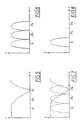
- the obtained layer presents stop-band characteristics according to figure 5, where the X-axis is frequency, the Y-axis is transmission and f 0 the desired transmission frequency. It should be noted that the reflection resonance is dimensioned for approximately the frequency 3f 0 . Since the elements are resonant at about 3f 0 , the packing density of the periodic pattern can furthermore be adapted so that no grating lobes occur before about 6f 0 .
- the inner layer 420 is dimensioned for a transmission resonance at f 0 , i.e. a pass-band filter is obtained, together with the flaws of such as mentioned above.
- a pass-band filter By combining this pass-band filter (see figure 6) with the previously dimensioned band-stop filter according to figure 5, which is placed closer to the surroundings, a pass-band filter (see figure 8) is obtained without multiple pass bands and with a considerable shift of the grating lobe occurrence on the outside of the surface/radome upwardly in the frequency direction to about 6f 0 .
- Figure 7 shows how the two different transmission diagrams appear, overlaid one upon the other.
- the layer closer to the surroundings (outer) has to be the reflecting layer which hides the transmitting layer (inner) for frequencies above the desired resonance frequency f 0 .
- the grating lobes will occur on the inside of the surface/radome closer to f 0 , but lack significance for the external radar signature.
- the distance 450, according to figure 4, between the two layers 410, 420 can be chosen in dependence upon characteristics that it is wished that the surface/radome should have.
- Other distances between the layers can of course be chosen depending on which characteristics are desired. It is also imaginable that the interspace between the layers consists of air, but for practical reasons a porous material is normally used, the dielectric characteristics of which are as similar to air as possible.
- the choice of elements is not limited to slits and dipoles, but instead any type of aperture elements whatsoever (slits, ring-slits, tri-slits etc.) and respectively any type of complementary conductive elements whatsoever (dipoles, rings, tripoles, etc.) can be combined in this construction.
- Arbitrary conductive materials like copper, aluminium etc., can be used for manufacturing of the aperture elements and the conductive elements. The choice between these can depend on factors like cost, machining, durability etc.
- the thickness of the conductive material which is used is normally of the order of tenths of mm to hundredths of mm thick.
- the conductive elements are arranged on an arbitrary dielectric such as for example glass-fibre, kevlar, thermoplastic etc. The choice between these can, as previously, depend on factors such as cost, machining, durability, temperature range etc.
- one or both of the layers may have several layers. This means that respective layers of apertures/conductive elements can consist of two or more layers with the same, or similar, type of element.
- the layers with aperture elements are separated with a dielectric at at least a distance which can ensure that the different layers are electrically insulated from one another.
- the layers with conductive elements are separated by at least the dielectric, on which they are arranged.
- the outer layer comprises two layers, it is imaginable that these are arranged with conductive elements on respective sides of a dielectric, on which they are arranged.
- the transmission resonance frequency and the reflection resonance frequency in each layer in the inner and the outer layer respectively can be substantially the same (as similar as possible in a manufacturing sense to construct each layer to have the same reflection resonance frequency or transmission resonance frequency) or lie somewhat shifted, up to and including 10% in terms of frequency relative to each other.
- the reason for choosing similar or somewhat varying frequencies for the different layers is entirely dependent on which characteristics it is desired that the frequency-selective surface should have. In the case where it is desired that the frequency-selective surface should be transparent for more than one transmission frequency, it may be suitable to choose a transmitting layer for each transmission frequency and to have a transmission resonant frequency for each transmission frequency.
- FIG. 9 shows a preferred embodiment of a frequency-selective surface 900 according to the present invention.
- the outer layer 910 comprises two layers 912, 914 with elements of dipole type in this embodiment.
- the inner layer 920 comprises a layer 922 with elements of the slit type.
- Incident 940 and emitted 942 electromagnetic radiation can in this way reach, and be transmitted from, sensor/antenna 930 at the desired frequency/frequencies.
Landscapes
- Aerials With Secondary Devices (AREA)
- Radar Systems Or Details Thereof (AREA)
- Details Of Aerials (AREA)
Description
Grating lobes are undesirable lobes, radiation, which occur due to interference when electromagnetic radiation at a suitable frequency meets or transmits through a surface with a periodic and symmetric pattern.
The problem with grating lobes is only coupled to the desire to reduce/alter the radar signature, on the condition that these do not already occur at an undesired resonant frequency, in which case even the sensor's/antenna's own characteristics are disturbed.
Each periodic pattern of electrically conductive elements is arranged to possess a reflection resonance frequency for electromagnetic radiation which is higher than the transmission frequency, preferably of the order of three times larger.
- Fig. 1
- shows a schematic example of an aeroplane's nose having a radome which can be provided with the invention,
- Fig. 2
- schematically shows an example of an earlier-known periodic pattern,
- Fig. 3
- shows an additional schematic example of an aeroplane's nose with a radome which can be provided with the invention,
- Fig. 4
- schematically shows an embodiment of the present invention,
- Fig. 5
- shows a schematic diagram of the frequency characteristics of a layer having a periodic pattern with conductive elements which are comprised in the present invention,
- Fig. 6
- shows a schematic diagram of the frequency characteristics of a layer having a periodic pattern with aperture elements which are comprised in the present invention,
- Fig. 7
- shows figures 5 and 6 in an overlaid relationship,
- Fig. 8
- shows the resulting frequency characteristics of a layer having conductive elements and a layer having aperture elements according to the present invention, and
- Fig. 9
- schematically shows an additional embodiment of the present invention.
The first and
Claims (10)
- A frequency-selective arrangement (120, 322, 400, 900) designed to transmit electromagnetic radiation (440, 442, 940, 942) around at least one predetermined transmission frequency and placed in front of one or more antenna arrangements (110, 310, 430, 930), characterized in that the frequency-selective arrangement comprises a number of layers, including at least one inner layer (420, 920) and one outermost layer (410, 910), whereby the inner layer (420, 920) is arranged closer than the outermost layer (410 910) to the antenna arrangement or the antenna arrangements (110, 310, 430, 930), where:the outermost layer (410, 910) comprises at least one electromagnetic reflecting layer (412, 912, 914) comprising a periodic pattern of electrically conductive elements, where said periodic pattern of electrically conductive elements is arranged to possess a reflection resonance frequency for electromagnetic radiation which is higher than said transmission frequency,the inner layer (420, 920) comprises at least one inner electromagnetic transmitting layer (422, 922) placed at a predetermined distance (450) from the outermost layer, said inner electromagnetic transmitting layer comprising a periodic pattern of aperture elements, wherein said periodic pattern of aperture elements is arranged to possess a transmission resonance frequency for electromagnetic radiation which is substantially equal to said transmission frequency.
- A frequency-selective arrangement according to claim 1, characterized in that said reflection resonance frequency is of the order of three times higher than said transmission frequency.
- A frequency-selective arrangement according to claim 1 or 2, characterized in that said predetermined distance between the inner and the outermost layer is approximately the same as λ/4 + nλ/2, where n=0, 1, 2, 3,... and where λ is the electrical wavelength.
- A frequency-selective arrangement according to any one of claims 1 to 3, characterized in that said outermost layer comprises two electromagnetic reflecting layers.
- A frequency-selective arrangement according to claim 4, characterized in that said two electromagnetic reflecting layers are designed with substantially the same reflection resonance frequencies.
- A frequency-selective arrangement according to claim 4, characterized in that said two electromagnetic reflecting layers are designed with reflection resonance frequencies which are shifted within 10% of one another.
- A frequency-selective arrangement according to any one of claims 1 to 6, characterized in that said inner layer comprises two electromagnetic transmitting layers.
- A frequency-selective arrangement according to claim 7, characterized in that said two electromagnetic transmitting layers are designed with substantially the same transmission frequencies.
- A frequency-selective arrangement according to claim 7, characterized in that said two electromagnetic transmitting layers are designed with transmission frequencies which are shifted within 10% of one another.
- A frequency-selective arrangement (120, 322, 400, 900) according to claim 1, characterized in that:the outermost layer (410, 910) comprises two electromagnetic reflecting layers (412, 912, 914) each comprising a periodic pattern of electrically conductive elements, where said periodic patterns of electrically conductive elements are arranged to possess a reflection resonance frequency for electromagnetic radiation which is of the order of three times higher than said transmission frequency,the inner layer (420, 920) is placed at a distance (450) from the outermost layer, which is approximately equal to λ/4, λ being the electrical wavelength.
Applications Claiming Priority (3)
| Application Number | Priority Date | Filing Date | Title |
|---|---|---|---|
| SE9502859A SE504815C2 (en) | 1995-08-17 | 1995-08-17 | Protection for one or more electromagnetic sensors |
| SE9502859 | 1995-08-17 | ||
| PCT/SE1996/000956 WO1997007558A1 (en) | 1995-08-17 | 1996-07-15 | Protector for one or more electromagnetic sensors |
Publications (2)
| Publication Number | Publication Date |
|---|---|
| EP0787370A1 EP0787370A1 (en) | 1997-08-06 |
| EP0787370B1 true EP0787370B1 (en) | 2003-10-29 |
Family
ID=20399201
Family Applications (1)
| Application Number | Title | Priority Date | Filing Date |
|---|---|---|---|
| EP96925227A Expired - Lifetime EP0787370B1 (en) | 1995-08-17 | 1996-07-15 | Protector for one or more electromagnetic sensors |
Country Status (10)
| Country | Link |
|---|---|
| US (1) | US5861860A (en) |
| EP (1) | EP0787370B1 (en) |
| JP (1) | JPH10507617A (en) |
| CN (1) | CN1080465C (en) |
| BR (1) | BR9606582A (en) |
| CA (1) | CA2202743A1 (en) |
| DE (1) | DE69630508T2 (en) |
| NO (1) | NO318660B1 (en) |
| SE (1) | SE504815C2 (en) |
| WO (1) | WO1997007558A1 (en) |
Families Citing this family (24)
| Publication number | Priority date | Publication date | Assignee | Title |
|---|---|---|---|---|
| US6285332B1 (en) * | 1999-09-10 | 2001-09-04 | Trw Inc. | Frequency selective reflector |
| DE19963003A1 (en) * | 1999-12-24 | 2001-06-28 | Bosch Gmbh Robert | Vehicle radar system, e.g. for adaptive cruise control, has dielectric focusing lens or radar dome without focusing in beam path with arrangement of ferromagnetic electrical conductor tracks |
| US6788273B1 (en) * | 2002-09-19 | 2004-09-07 | Raytheon Company | Radome compensation using matched negative index or refraction materials |
| US6891517B2 (en) * | 2003-04-08 | 2005-05-10 | Ppg Industries Ohio, Inc. | Conductive frequency selective surface utilizing arc and line elements |
| FR2864020B1 (en) * | 2003-12-19 | 2006-02-10 | Airbus France | AIRCRAFT NOSE WITH SHIELD |
| JP4784115B2 (en) * | 2005-03-15 | 2011-10-05 | 横浜ゴム株式会社 | Radome |
| US7414593B2 (en) * | 2006-02-24 | 2008-08-19 | Alliant Techsystems Inc. | Thermoformed frequency selective surface |
| US7583238B2 (en) * | 2007-01-19 | 2009-09-01 | Northrop Grumman Systems Corporation | Radome for endfire antenna arrays |
| WO2009053722A1 (en) * | 2007-10-26 | 2009-04-30 | Bae System Plc | Reducing radar signatures |
| DK2351382T3 (en) | 2008-09-26 | 2013-08-19 | Oticon As | Hearing aid with interchangeable sheath parts and wireless communication |
| CN103384357A (en) * | 2008-09-26 | 2013-11-06 | 奥迪康有限公司 | Hearing-aid and wireless antenna |
| JP5435507B2 (en) * | 2011-04-14 | 2014-03-05 | 日本電業工作株式会社 | Omnidirectional antenna |
| US9564681B2 (en) * | 2013-11-11 | 2017-02-07 | Gogo Llc | Radome having localized areas of reduced radio signal attenuation |
| US9608321B2 (en) * | 2013-11-11 | 2017-03-28 | Gogo Llc | Radome having localized areas of reduced radio signal attenuation |
| US10153547B2 (en) * | 2015-07-15 | 2018-12-11 | Raytheon Company | Armored radome |
| US9876280B1 (en) * | 2015-12-07 | 2018-01-23 | Raytheon Company | Radome with radio frequency filtering surface |
| CN105633592B (en) * | 2016-03-24 | 2018-08-24 | 电子科技大学 | artificial electromagnetic shielding material |
| EP3442079B1 (en) * | 2016-04-08 | 2020-11-25 | Mitsubishi Electric Corporation | Resonant element for frequency selective plate, frequency selective plate and antenna device |
| CN108614241A (en) * | 2018-05-03 | 2018-10-02 | 合肥光博量子科技有限公司 | A kind of fire-retardant dustproof rain cover for protecting radar |
| CN110311223B (en) * | 2019-07-25 | 2021-09-24 | 哈尔滨工业大学 | Signal Enhanced Plasma Stealth Antenna Window |
| JP7285801B2 (en) * | 2020-04-16 | 2023-06-02 | 三菱電機株式会社 | Communication device and electronic toll collection system |
| JP7811510B2 (en) * | 2022-04-20 | 2026-02-05 | 横浜ゴム株式会社 | Mantle Cloak embedded radome |
| JP7405316B1 (en) * | 2022-06-27 | 2023-12-26 | 大日本印刷株式会社 | Reflective structure, reflective structure manufacturing method, and frequency selective reflector set |
| WO2024024849A1 (en) * | 2022-07-27 | 2024-02-01 | 富士フイルム株式会社 | Meta-surface structure |
Family Cites Families (6)
| Publication number | Priority date | Publication date | Assignee | Title |
|---|---|---|---|---|
| DE3402659A1 (en) * | 1984-01-26 | 1985-08-01 | Messerschmitt-Bölkow-Blohm GmbH, 8012 Ottobrunn | REFLECTOR ANTENNA FOR OPERATION IN MULTIPLE FREQUENCY RANGES |
| US5103241A (en) * | 1989-07-28 | 1992-04-07 | Hughes Aircraft Company | High Q bandpass structure for the selective transmission and reflection of high frequency radio signals |
| CA2006481C (en) * | 1989-12-19 | 1999-09-21 | Adrian W. Alden | Low noise dual polarization electromagnetic power reception and conversion system |
| US5208603A (en) * | 1990-06-15 | 1993-05-04 | The Boeing Company | Frequency selective surface (FSS) |
| GB9019628D0 (en) * | 1990-09-07 | 1992-04-08 | Univ Loughborough | Reconfigurable frequency selective surface |
| US5162809A (en) * | 1990-10-23 | 1992-11-10 | Hughes Aircraft Company | Polarization independent frequency selective surface for diplexing two closely spaced frequency bands |
-
1995
- 1995-08-17 SE SE9502859A patent/SE504815C2/en not_active IP Right Cessation
-
1996
- 1996-07-15 WO PCT/SE1996/000956 patent/WO1997007558A1/en not_active Ceased
- 1996-07-15 CN CN96190926A patent/CN1080465C/en not_active Expired - Lifetime
- 1996-07-15 CA CA002202743A patent/CA2202743A1/en not_active Abandoned
- 1996-07-15 EP EP96925227A patent/EP0787370B1/en not_active Expired - Lifetime
- 1996-07-15 BR BR9606582A patent/BR9606582A/en not_active IP Right Cessation
- 1996-07-15 JP JP9509198A patent/JPH10507617A/en active Pending
- 1996-07-15 DE DE69630508T patent/DE69630508T2/en not_active Expired - Lifetime
- 1996-08-16 US US08/698,708 patent/US5861860A/en not_active Expired - Lifetime
-
1997
- 1997-04-15 NO NO19971724A patent/NO318660B1/en unknown
Also Published As
| Publication number | Publication date |
|---|---|
| EP0787370A1 (en) | 1997-08-06 |
| US5861860A (en) | 1999-01-19 |
| DE69630508T2 (en) | 2004-08-05 |
| JPH10507617A (en) | 1998-07-21 |
| WO1997007558A1 (en) | 1997-02-27 |
| BR9606582A (en) | 1998-05-26 |
| SE9502859L (en) | 1997-02-18 |
| NO318660B1 (en) | 2005-04-25 |
| CN1161108A (en) | 1997-10-01 |
| SE504815C2 (en) | 1997-04-28 |
| DE69630508D1 (en) | 2003-12-04 |
| CA2202743A1 (en) | 1997-02-27 |
| SE9502859D0 (en) | 1995-08-17 |
| NO971724D0 (en) | 1997-04-15 |
| CN1080465C (en) | 2002-03-06 |
| NO971724L (en) | 1997-06-16 |
Similar Documents
| Publication | Publication Date | Title |
|---|---|---|
| US5861860A (en) | Protector for one or more electromagnetic sensors | |
| US5208603A (en) | Frequency selective surface (FSS) | |
| US4656487A (en) | Electromagnetic energy passive filter structure | |
| EP1418643B1 (en) | Microstrip antenna array with periodic filters | |
| US3961333A (en) | Radome wire grid having low pass frequency characteristics | |
| US5949387A (en) | Frequency selective surface (FSS) filter for an antenna | |
| US5400043A (en) | Absorptive/transmissive radome | |
| US6876320B2 (en) | Anti-radar space-filling and/or multilevel chaff dispersers | |
| US8159407B2 (en) | Radome with integrated plasma shutter | |
| US4125841A (en) | Space filter | |
| US6836258B2 (en) | Complementary dual antenna system | |
| JP2000216623A (en) | Multiple pattern antenna having frequency selection zone or polarized wave sensing zone | |
| US4684954A (en) | Electromagnetic energy shield | |
| EP2502306B1 (en) | Metamaterial band stop filter for waveguides | |
| US3864690A (en) | Multifrequency operating radome | |
| US5014070A (en) | Radar camouflage material | |
| GB2378820A (en) | Electromagnetic filter | |
| US5036323A (en) | Active radar stealth device | |
| JP7130129B2 (en) | radar sensor | |
| CN109769398A (en) | Optically transparent electromagnetic shielding element including multiple regions | |
| Antonopoulos et al. | Multilayer frequency-selective surfaces for millimetre and submillimetre wave applications | |
| US6130653A (en) | Compact stripline Rotman lens | |
| US5592186A (en) | Sectional filter assembly | |
| JPS62171209A (en) | Leakage waveguide antenna and manufacture of the same | |
| US6211843B1 (en) | Cover for camouflaging military facilities |
Legal Events
| Date | Code | Title | Description |
|---|---|---|---|
| PUAI | Public reference made under article 153(3) epc to a published international application that has entered the european phase |
Free format text: ORIGINAL CODE: 0009012 |
|
| 17P | Request for examination filed |
Effective date: 19970327 |
|
| AK | Designated contracting states |
Kind code of ref document: A1 Designated state(s): DE FI FR IT |
|
| 17Q | First examination report despatched |
Effective date: 20001103 |
|
| GRAH | Despatch of communication of intention to grant a patent |
Free format text: ORIGINAL CODE: EPIDOS IGRA |
|
| GRAS | Grant fee paid |
Free format text: ORIGINAL CODE: EPIDOSNIGR3 |
|
| GRAA | (expected) grant |
Free format text: ORIGINAL CODE: 0009210 |
|
| AK | Designated contracting states |
Kind code of ref document: B1 Designated state(s): DE FI FR IT |
|
| REF | Corresponds to: |
Ref document number: 69630508 Country of ref document: DE Date of ref document: 20031204 Kind code of ref document: P |
|
| RAP2 | Party data changed (patent owner data changed or rights of a patent transferred) |
Owner name: TELEFONAKTIEBOLAGET LM ERICSSON (PUBL) |
|
| ET | Fr: translation filed | ||
| PLBE | No opposition filed within time limit |
Free format text: ORIGINAL CODE: 0009261 |
|
| STAA | Information on the status of an ep patent application or granted ep patent |
Free format text: STATUS: NO OPPOSITION FILED WITHIN TIME LIMIT |
|
| 26N | No opposition filed |
Effective date: 20040730 |
|
| PGFP | Annual fee paid to national office [announced via postgrant information from national office to epo] |
Ref country code: FI Payment date: 20070730 Year of fee payment: 12 |
|
| PGFP | Annual fee paid to national office [announced via postgrant information from national office to epo] |
Ref country code: IT Payment date: 20070727 Year of fee payment: 12 |
|
| PG25 | Lapsed in a contracting state [announced via postgrant information from national office to epo] |
Ref country code: FI Free format text: LAPSE BECAUSE OF NON-PAYMENT OF DUE FEES Effective date: 20080715 |
|
| PG25 | Lapsed in a contracting state [announced via postgrant information from national office to epo] |
Ref country code: IT Free format text: LAPSE BECAUSE OF NON-PAYMENT OF DUE FEES Effective date: 20080715 |
|
| REG | Reference to a national code |
Ref country code: FR Ref legal event code: PLFP Year of fee payment: 20 |
|
| PGFP | Annual fee paid to national office [announced via postgrant information from national office to epo] |
Ref country code: DE Payment date: 20150729 Year of fee payment: 20 |
|
| PGFP | Annual fee paid to national office [announced via postgrant information from national office to epo] |
Ref country code: FR Payment date: 20150717 Year of fee payment: 20 |
|
| REG | Reference to a national code |
Ref country code: DE Ref legal event code: R071 Ref document number: 69630508 Country of ref document: DE |