EP0786913A2 - Radio call receiver - Google Patents
Radio call receiver Download PDFInfo
- Publication number
- EP0786913A2 EP0786913A2 EP97101133A EP97101133A EP0786913A2 EP 0786913 A2 EP0786913 A2 EP 0786913A2 EP 97101133 A EP97101133 A EP 97101133A EP 97101133 A EP97101133 A EP 97101133A EP 0786913 A2 EP0786913 A2 EP 0786913A2
- Authority
- EP
- European Patent Office
- Prior art keywords
- code
- receiver
- password
- radio
- section
- Prior art date
- Legal status (The legal status is an assumption and is not a legal conclusion. Google has not performed a legal analysis and makes no representation as to the accuracy of the status listed.)
- Withdrawn
Links
- 238000000034 method Methods 0.000 claims description 8
- 230000006870 function Effects 0.000 abstract description 4
- 238000001514 detection method Methods 0.000 description 3
- 238000010586 diagram Methods 0.000 description 3
- 238000012546 transfer Methods 0.000 description 3
- 238000004891 communication Methods 0.000 description 2
- 230000005764 inhibitory process Effects 0.000 description 1
- 230000000977 initiatory effect Effects 0.000 description 1
- 238000012986 modification Methods 0.000 description 1
- 230000004048 modification Effects 0.000 description 1
- 238000012544 monitoring process Methods 0.000 description 1
- 230000002093 peripheral effect Effects 0.000 description 1
Images


Classifications
-
- H—ELECTRICITY
- H04—ELECTRIC COMMUNICATION TECHNIQUE
- H04B—TRANSMISSION
- H04B5/00—Near-field transmission systems, e.g. inductive or capacitive transmission systems
-
- H—ELECTRICITY
- H04—ELECTRIC COMMUNICATION TECHNIQUE
- H04W—WIRELESS COMMUNICATION NETWORKS
- H04W8/00—Network data management
- H04W8/22—Processing or transfer of terminal data, e.g. status or physical capabilities
- H04W8/24—Transfer of terminal data
- H04W8/245—Transfer of terminal data from a network towards a terminal
-
- G—PHYSICS
- G08—SIGNALLING
- G08B—SIGNALLING OR CALLING SYSTEMS; ORDER TELEGRAPHS; ALARM SYSTEMS
- G08B5/00—Visible signalling systems, e.g. personal calling systems, remote indication of seats occupied
- G08B5/22—Visible signalling systems, e.g. personal calling systems, remote indication of seats occupied using electric transmission; using electromagnetic transmission
- G08B5/222—Personal calling arrangements or devices, i.e. paging systems
- G08B5/223—Personal calling arrangements or devices, i.e. paging systems using wireless transmission
- G08B5/224—Paging receivers with visible signalling details
- G08B5/229—Paging receivers with visible signalling details with other provisions not elsewhere provided for
-
- H—ELECTRICITY
- H04—ELECTRIC COMMUNICATION TECHNIQUE
- H04W—WIRELESS COMMUNICATION NETWORKS
- H04W88/00—Devices specially adapted for wireless communication networks, e.g. terminals, base stations or access point devices
- H04W88/02—Terminal devices
- H04W88/022—Selective call receivers
Definitions
- the present invention relates to a radio call receiver, in particular, to a radio call receiver for informing a user of the call on determining that a received ID code matches a registered ID code previously registered in the device, and storing and displaying the corresponding message.
- Conventional systems for calling radio call receivers generally have the following configuration.
- a radio call transmitter converts the telephone number into an address signal corresponding to the unique ID code of a radio call receiver.
- a base station organizes as many address signals as radio call receivers to be called, and transmits the call signals with synchronization signals.
- Each radio call receiver initiates a call to its owner (user) if the unique ID code that is the address signal of the radio call receiver in the call signal matches the contents of its registered ID code.
- Each address signal (1), ..., (n) comprises a fixed address section A that is a fixed ID code (corresponding to a telephone number) unique to a radio call receiver and an additional address section B that is a password set individually by an owner or an user.
- the fixed ID code is provided by a communication company.
- a caller inputs the telephone number of a called party and a subsequent password thereof to a radio call transmitter via a telephone and a public switched network.
- a radio call receiver does not carry out a message reception operation and a calling operation corresponding to the address signal unless a unique ID code and a subsequent additional address are specified in the call signal transmitted by a base station and match registered data (Japanese Patent Laid-Open Application No. 2-29036) .
- the conventional radio call receivers which are intended to prevent unauthorized use have the following problems.
- a first problem is degraded operability on the caller side. That is, input of a telephone number (a fixed address) and the password of a called party are required to connect to a receiver.
- a second problem is limited service functions among systems. That is, conventional receivers cannot cope with transfer informing services from other systems that do not require the input of a password (an additional address).
- a third problem is imperfect security for received information. That is, if the receiver should be lost, the contents of received messages may be leaked out easily to the third person.
- an object of the present invention to provide a radio call receiver that solves the above problems, which improves security in case of loss, and which also improves operability on the caller side.
- a radio call receiver of the present invention comprises a decoder for decoding a received radio selection call signal to detect an ID code, an additional address and a message, a memory for storing a registered ID code, and a control means.
- the control means compares said detected ID code to said registered ID code, compares a password of an additional address added to said ID code to an registered password in case that said decoder detects said additional address, and disables the receiver when the two passwords coincide with each other.
- a receiving method of the present invention comprises the following steps. First, a received radio selection call signal is decoded, and an ID code and a message are detected, said ID code is compared to a registered ID code, it is checked whether an additional address added to said ID code has been received, and a password in said additional address is compared to an registered password. Thereafter, the receiver is disabled if the two passwords coincide with each other.
- FIG.1 is a functional block diagram showing one embodiment of this invention.
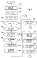
- FIG.2 is a flowchart showing the operation of one embodiment of this invention.
- FIG.3 is a functional block diagram showing a variation of the control section shown in FIG.1.
- FIG.4 shows one embodiment of radio selection call signal format.
- a radio call receiver 100 comprises a key input section 10 with which a user performs setting operations; a receiving section 20 for receiving radio signals; a decoding section 30 for decoding received signal data; a control section 40; a memory section 50; a display section 70 for displaying messages; a speaker 80 that generates sounds; and a drive circuit 60 for driving these peripheral devices in accordance with the control section 40.
- the control section 40 monitors and controls the overall device, and includes a password registration section 41 for accepting the registration of passwords and for storing them, a password comparison section 42 for determining whether or not an additional address and a registered password match, and an ID code determination section 43 for determining whether or not a unique ID code and a registered ID code match.
- the memory section 50 includes an ID-ROM section 51 for storing various parameter information such as registered ID codes, a RAM 52 for storing received messages, and a ROM 53 for storing control software information for the operation of the control section 40.
- the owner can arbitrarily register a password by executing setting and registration operations from the key input section 10.
- the password registration section 41 accepts and registers the password.
- the accepted password may be stored in the memory section 50.
- An ID code (a unique ID code) is registered in advance by the communication company using a well-known appropriate technique. Whether or not an ID code has been registered can be known from a registration ID status provided in the ID-ROM section 51.
- the owner's contact number can be registered in the ID-ROM section 51.
- a call signal on a radio line for calling the radio call receiver 100 includes the telephone number of a called party who is the owner, that is, a unique ID code.
- An additional address may be added to the call signal as shown in FIG.4.
- the reception section 20 receives the call signal on the radio line and obtains the unique ID code, the additional address (if any) and a message.
- the decoder 30 decodes the received data and transmits it to the control section 40.
- the control section 40 checks whether an ID code is registered in the ID-ROM 51, and if so, constantly monitors the unique ID code transmitted by the base station via the reception section 20 and the decoder 30. On detecting the unique ID code in the received data, the control section 40 checks whether or not it includes an additional address, and if not, determines that the call is of a normal type. The ID code determination section 43 determines whether or not the ID code matches the registered ID code stored in the ID-ROM section 51. If they match, the control section 40 receives the message corresponding to the ID code of the receiver which is contained in the call signal, and controls the drive circuit 60, the display section 70, and the speaker 80 so as to initiate a call notifying operation including the display of the received message. The received message can be stored in the RAM 52 and displayed on the display section 70 at any desired time by the operation of the key input section 10.
- the password comparison section 42 determines whether or not the address matches the password registered in the password registration section 41. If they match, the control section 40 determines that this is a protect instruction for preventing unauthorized use, and provides a read inhibition protect for the registered ID code in the ID-ROM section 51 (that is, the ID code is masked so that it cannot be read) to disable the ID code (that is, stop the message reception and display functions).
- the control means can be set in microprocessor.
- the owner of the radio call receiver 100 operates the key input section 10 in advance to input a password to the control section 40 in order to register it in the password registration section 41. To change the registered password, the owner inputs a new password with the current password. If the receiver should be lost or stolen and obtained by a third party, the rightful owner will use a telephone to access a radio call transmitter via a public switched network, input his or her password as the additional address in addition to his or her unique ID code which is conventionally used in a call signal, and transmit the data to the radio call receiver 100 via a radio line.
- the reception section 20 prepares to receive the call signal on the radio line, establishes synchronization by detecting a synchronizing signal, and then transfers to a reception initiation mode (steps S100 and S101 in FIG. 2) .
- the decoder 30 decodes and converts the data received by the receiving section 20, and then sends it to the control section 40.
- the control section 40 obtains the unique ID code and the additional address from the received data (step S102). If an ID code is registered in the ID-ROM section 51 of the memory section 50, that is, the registration ID status is "1" (step S103), the ID code determination section 43 determines whether or not the registered ID code stored in the ID-ROM section 51 matches the received unique ID code (step S104).
- control section 40 If there is not an ID code registered or the ID codes do not match, the control section 40 returns to a reception waiting state. If the ID codes match, the control section 40 determines that this is a call to the receiver, and causes the password comparison section 42 to compare the input additional address, if any, to the password stored in the password registration section 41 (steps S105 and S106). If there is not an additional address input or the address and the password do not match, the control section performs a normal operation (step 120). This normal calling operation is a well known technique, and its detailed description is omitted.
- the control section 40 determines that the message includes a "protect instruction” and forces the registered ID status to be set to "0" (no registration; protect state), thereby disabling the comparison to subsequent unique ID codes (step S107).
- the control section 40 simultaneously sets the contents of the message in a secret mode to prevent the leakage of the received message stored in the device (step S108) and displays on the display screen 70 the owner's contact number registered in the ID-ROM section 51 (step S109). After that, the control section 40 shifts to a protect cancellation waiting mode (step S110). The owner's contact number is displayed, so if the receiver should be lost, it is likely that it will be returned to the owner.
- the control section 40 detects that the input password matches the password registered in the password registration section 41, and cancels the "protect state", that is, sets the registered ID status to "1". This enables the reception of subsequent call signals (display of received message) (step S112).
- FIG.3 is a block diagram of a variation of the control section 40 according to this invention.
- the control section 40 has a timer section 44 for managing time and a battery replacement detection section 45 for monitoring the replacement of a battery.
- the specified period of time is, for example, from several hours to several days.
- control section 40 causes the password comparison section 42 to determine whether or not the password input from the key input section matches the password registered in the password registration section 41, and if they match, returns the registered ID status to "1".
- the radio call receiver On detecting that the ID code in the radio selection call signal matches the ID code previously registered in the device, the radio call receiver according to this invention determines that the call is to the receiver and stores and displays the corresponding message.
- a password is registered in advance (a registered password), and an additional address is added to the ID code in the radio selection call signal. If this additional address matches the registered password, the registered ID code of the receiver is invalidated (protect state), and the reception and display of the message are prohibited.
- the caller the sender
- This receiver can deal with transfer informing services from other systems that do not require the input of a password (an additional address).
- the rightful owner can send via remote control a radio selection call signal including the registered password as the additional address to disable the receiver.
- the user thereby prevents the contents of the received message from being leaked to a third party, in order to protect the owner's data and privacy (to improve security).
- the owner does not know that the receiver has been lost, the owner's data and privacy can be protected by setting the registered ID in the protect state by executing timing control. That is, the receiver becomes disabled when the timer means detects that no key operation has been performed over a specified period of time or when the battery replacement detection means detects that the battery has been replaced due to its exhaustion.
Landscapes
- Engineering & Computer Science (AREA)
- Computer Networks & Wireless Communication (AREA)
- Physics & Mathematics (AREA)
- Signal Processing (AREA)
- Electromagnetism (AREA)
- General Physics & Mathematics (AREA)
- Databases & Information Systems (AREA)
- Mobile Radio Communication Systems (AREA)
Abstract
A radio call receiver can be disabled by its rightful owner when it is lost or stolen. When a radio call receiver 100 receives a radio selection call signal, a decoding section 30 decodes the received data and transmits it to a control section 40. The control section 40 obtains a unique ID code and an additional address from the received data. An ID code determination section 43 compares the unique ID code to the registered ID code stored in an ID-ROM section 51. If they match and there is an additional address included in the signal, a password comparison section 42 compares the additional address to the registered password. If they match, the control section stops the functions for receiving the message in the call signal and displaying the received message.
Description
- The present invention relates to a radio call receiver, in particular, to a radio call receiver for informing a user of the call on determining that a received ID code matches a registered ID code previously registered in the device, and storing and displaying the corresponding message.
- Conventional systems for calling radio call receivers generally have the following configuration. When a caller transmits the telephone number of a called party from a telephone via a public switched network, a radio call transmitter converts the telephone number into an address signal corresponding to the unique ID code of a radio call receiver. A base station organizes as many address signals as radio call receivers to be called, and transmits the call signals with synchronization signals. Each radio call receiver initiates a call to its owner (user) if the unique ID code that is the address signal of the radio call receiver in the call signal matches the contents of its registered ID code.
- A system has been proposed in order to prevent mislaid radio call receivers from being improperly used by people other than the rightful owner. Each address signal (1), ..., (n) comprises a fixed address section A that is a fixed ID code (corresponding to a telephone number) unique to a radio call receiver and an additional address section B that is a password set individually by an owner or an user. The fixed ID code is provided by a communication company. A caller inputs the telephone number of a called party and a subsequent password thereof to a radio call transmitter via a telephone and a public switched network. A radio call receiver does not carry out a message reception operation and a calling operation corresponding to the address signal unless a unique ID code and a subsequent additional address are specified in the call signal transmitted by a base station and match registered data (Japanese Patent Laid-Open Application No. 2-29036) .
- The conventional radio call receivers which are intended to prevent unauthorized use have the following problems. A first problem is degraded operability on the caller side. That is, input of a telephone number (a fixed address) and the password of a called party are required to connect to a receiver. A second problem is limited service functions among systems. That is, conventional receivers cannot cope with transfer informing services from other systems that do not require the input of a password (an additional address). A third problem is imperfect security for received information. That is, if the receiver should be lost, the contents of received messages may be leaked out easily to the third person.
- It is, therefore, an object of the present invention to provide a radio call receiver that solves the above problems, which improves security in case of loss, and which also improves operability on the caller side.
- A radio call receiver of the present invention comprises a decoder for decoding a received radio selection call signal to detect an ID code, an additional address and a message, a memory for storing a registered ID code, and a control means. The control means compares said detected ID code to said registered ID code, compares a password of an additional address added to said ID code to an registered password in case that said decoder detects said additional address, and disables the receiver when the two passwords coincide with each other.
- A receiving method of the present invention comprises the following steps. First, a received radio selection call signal is decoded, and an ID code and a message are detected, said ID code is compared to a registered ID code, it is checked whether an additional address added to said ID code has been received, and a password in said additional address is compared to an registered password. Thereafter, the receiver is disabled if the two passwords coincide with each other.
- In this receiver and receiving method, if the receiver is lost, then a user easily protect stored information.
- The above and other objects, features and advantages of the present invention will become apparent from the following detailed description taken with reference to the accompanying drawing in which :
- FIG.1 is a functional block diagram showing one embodiment of this invention.
- FIG.2 is a flowchart showing the operation of one embodiment of this invention.
- FIG.3 is a functional block diagram showing a variation of the control section shown in FIG.1.
- FIG.4 shows one embodiment of radio selection call signal format.
- FIG.1, a
radio call receiver 100 comprises akey input section 10 with which a user performs setting operations; areceiving section 20 for receiving radio signals; adecoding section 30 for decoding received signal data; acontrol section 40; amemory section 50; adisplay section 70 for displaying messages; aspeaker 80 that generates sounds; and adrive circuit 60 for driving these peripheral devices in accordance with thecontrol section 40. Thecontrol section 40 monitors and controls the overall device, and includes apassword registration section 41 for accepting the registration of passwords and for storing them, apassword comparison section 42 for determining whether or not an additional address and a registered password match, and an IDcode determination section 43 for determining whether or not a unique ID code and a registered ID code match. Thememory section 50 includes an ID-ROM section 51 for storing various parameter information such as registered ID codes, aRAM 52 for storing received messages, and aROM 53 for storing control software information for the operation of thecontrol section 40. - The owner can arbitrarily register a password by executing setting and registration operations from the
key input section 10. Thepassword registration section 41 accepts and registers the password. The accepted password may be stored in thememory section 50. An ID code (a unique ID code) is registered in advance by the communication company using a well-known appropriate technique. Whether or not an ID code has been registered can be known from a registration ID status provided in the ID-ROM section 51. The owner's contact number can be registered in the ID-ROM section 51. - A call signal on a radio line for calling the
radio call receiver 100 includes the telephone number of a called party who is the owner, that is, a unique ID code. An additional address may be added to the call signal as shown in FIG.4. Thereception section 20 receives the call signal on the radio line and obtains the unique ID code, the additional address (if any) and a message. Thedecoder 30 decodes the received data and transmits it to thecontrol section 40. - The
control section 40 checks whether an ID code is registered in the ID-ROM 51, and if so, constantly monitors the unique ID code transmitted by the base station via thereception section 20 and thedecoder 30. On detecting the unique ID code in the received data, thecontrol section 40 checks whether or not it includes an additional address, and if not, determines that the call is of a normal type. The IDcode determination section 43 determines whether or not the ID code matches the registered ID code stored in the ID-ROM section 51. If they match, thecontrol section 40 receives the message corresponding to the ID code of the receiver which is contained in the call signal, and controls thedrive circuit 60, thedisplay section 70, and thespeaker 80 so as to initiate a call notifying operation including the display of the received message. The received message can be stored in theRAM 52 and displayed on thedisplay section 70 at any desired time by the operation of thekey input section 10. - If the received data includes an additional address, the
password comparison section 42 determines whether or not the address matches the password registered in thepassword registration section 41. If they match, thecontrol section 40 determines that this is a protect instruction for preventing unauthorized use, and provides a read inhibition protect for the registered ID code in the ID-ROM section 51 (that is, the ID code is masked so that it cannot be read) to disable the ID code (that is, stop the message reception and display functions). The control means can be set in microprocessor. - Next, an operation performed to prevent unauthorized use according to this invention is described in detail with reference to FIG. 1 and FIG. 2.
- The owner of the
radio call receiver 100 operates thekey input section 10 in advance to input a password to thecontrol section 40 in order to register it in thepassword registration section 41. To change the registered password, the owner inputs a new password with the current password. If the receiver should be lost or stolen and obtained by a third party, the rightful owner will use a telephone to access a radio call transmitter via a public switched network, input his or her password as the additional address in addition to his or her unique ID code which is conventionally used in a call signal, and transmit the data to theradio call receiver 100 via a radio line. - In the
radio call receiver 100, thereception section 20 prepares to receive the call signal on the radio line, establishes synchronization by detecting a synchronizing signal, and then transfers to a reception initiation mode (steps S100 and S101 in FIG. 2) . Thedecoder 30 decodes and converts the data received by thereceiving section 20, and then sends it to thecontrol section 40. Thecontrol section 40 obtains the unique ID code and the additional address from the received data (step S102). If an ID code is registered in the ID-ROM section 51 of thememory section 50, that is, the registration ID status is "1" (step S103), the IDcode determination section 43 determines whether or not the registered ID code stored in the ID-ROM section 51 matches the received unique ID code (step S104). If there is not an ID code registered or the ID codes do not match, thecontrol section 40 returns to a reception waiting state. If the ID codes match, thecontrol section 40 determines that this is a call to the receiver, and causes thepassword comparison section 42 to compare the input additional address, if any, to the password stored in the password registration section 41 (steps S105 and S106). If there is not an additional address input or the address and the password do not match, the control section performs a normal operation (step 120). This normal calling operation is a well known technique, and its detailed description is omitted. If an additional address has been transmitted from the caller and it matches the password for the receiver, thecontrol section 40 determines that the message includes a "protect instruction" and forces the registered ID status to be set to "0" (no registration; protect state), thereby disabling the comparison to subsequent unique ID codes (step S107). Thecontrol section 40 simultaneously sets the contents of the message in a secret mode to prevent the leakage of the received message stored in the device (step S108) and displays on thedisplay screen 70 the owner's contact number registered in the ID-ROM section 51 (step S109). After that, thecontrol section 40 shifts to a protect cancellation waiting mode (step S110). The owner's contact number is displayed, so if the receiver should be lost, it is likely that it will be returned to the owner. - If the receiver is returned to the rightful owner and when the owner inputs the registered password from the key input section 10 (step S111), the
control section 40 detects that the input password matches the password registered in thepassword registration section 41, and cancels the "protect state", that is, sets the registered ID status to "1". This enables the reception of subsequent call signals (display of received message) (step S112). - Next, a second embodiment of this invention is described in detail. FIG.3 is a block diagram of a variation of the
control section 40 according to this invention. In addition to thepassword registration section 41, thepassword comparison section 42, and the IDcode determination section 43, thecontrol section 40 has atimer section 44 for managing time and a batteryreplacement detection section 45 for monitoring the replacement of a battery. Thetimer section 44 monitors the operation of switches in thekey input section 10 over a specified period of time. If no switch operation has been performed over the specified period of time, thecontrol section 40 masks the registered ID code in the ID-ROM section 50 so that it cannot be read (registered ID status = 0). Thereby, the reception and display of message are inhibited. The specified period of time is, for example, from several hours to several days. - The battery
exchange detection section 42 monitors the condition of the battery (not shown), and detects whether it has been replaced). When the battery is replaced, thecontrol section 40 masks the registered ID code in the ID-ROM section 51 (registered ID status = 0) so that it cannot be read. - These functions can prevent the receiver from receiving and displaying messages, even though the owner does not know that the receiver has been lost. In this case, the rightful owner can use the receiver again by inputting the registered password. That is, the
control section 40 causes thepassword comparison section 42 to determine whether or not the password input from the key input section matches the password registered in thepassword registration section 41, and if they match, returns the registered ID status to "1". - On detecting that the ID code in the radio selection call signal matches the ID code previously registered in the device, the radio call receiver according to this invention determines that the call is to the receiver and stores and displays the corresponding message. A password is registered in advance (a registered password), and an additional address is added to the ID code in the radio selection call signal. If this additional address matches the registered password, the registered ID code of the receiver is invalidated (protect state), and the reception and display of the message are prohibited. Thus, in normal operations, the caller (the sender) is required to input only the telephone number (the fixed address) of the receiver corresponding to the ID code to prevent operability from being degraded. This receiver can deal with transfer informing services from other systems that do not require the input of a password (an additional address). If the receiver should be lost or stolen, the rightful owner can send via remote control a radio selection call signal including the registered password as the additional address to disable the receiver. The user thereby prevents the contents of the received message from being leaked to a third party, in order to protect the owner's data and privacy (to improve security).
- Even though the owner does not know that the receiver has been lost, the owner's data and privacy can be protected by setting the registered ID in the protect state by executing timing control. That is, the receiver becomes disabled when the timer means detects that no key operation has been performed over a specified period of time or when the battery replacement detection means detects that the battery has been replaced due to its exhaustion.
- While the present invention has been described in connection with certain preferred embodiments, it is to be understood that the subject matter encompassed by the present invention is not limited to those specific embodiments. On the contrary, it is intended to include all alternatives, modifications and equivalents as can be included within the spirit and scope of the following claims.
Claims (13)
- A radio call receiver for displaying a message comprising:a decoder for decoding a received radio selection call signal to detect an ID code, a password and a message;a memory for storing a registered ID code; andcontrol means for (a) comparing said detected ID code to said registered ID code, (b) comparing said password to a preset password, and (c) disabling said receiver if said two passwords are the same.
- The radio call receiver as claimed in claim 1, wherein said control means prevents said registered ID code from being read from said memory when said two passwords coincide with each other.
- The radio call receiver as claimed in claim 1, wherein said control means prevents said message from being displayed when said two passwords coincide with each other.
- The radio call receiver as claimed in claim 1, wherein said control means stores said preset password.
- The radio call receiver as claimed in claim 1, wherein said memory stores said preset password.
- The radio call receiver as claimed in claim 1, wherein said control means further comprises means for disabling said receiver when no input operation has been performed for a predetermined period of time.
- The radio call receiver as claimed in claim 1, wherein said control means disables said receiver when a battery has been replaced.
- The radio call receiver as claimed in claim 1, further comprising means for entering said preset password.
- The radio call receiver as claimed in claim 1, wherein said control means further comprises means for restoring normal operation of said receiver responsive to input of said preset password via said entering means.
- A receiving method of radio selective call signal, comprising the steps of:decoding a received radio selection call signal to detect an ID code, and a message;comparing said ID code to a registered ID code;checking whether a password added to said ID code has been received;comparing said password to a preset password; anddisabling said receiver when said two passwords are the same.
- The receiving method as claimed in claim 10, further comprising the step of:
preventing any stored message from being displayed after said disabling step. - The receiving method as claimed in claim 10, further comprising the step of:
displaying information about an owner after said disabling step. - The receiving method of radio selective call signal as claimed in claim 10, further comprising the step of:
restoring operation of said receiver upon input of said preset password.
Applications Claiming Priority (3)
| Application Number | Priority Date | Filing Date | Title |
|---|---|---|---|
| JP8012006A JPH09205662A (en) | 1996-01-26 | 1996-01-26 | Radio call receiver |
| JP1200696 | 1996-01-26 | ||
| JP12006/96 | 1996-01-26 |
Publications (2)
| Publication Number | Publication Date |
|---|---|
| EP0786913A2 true EP0786913A2 (en) | 1997-07-30 |
| EP0786913A3 EP0786913A3 (en) | 1999-09-15 |
Family
ID=11793510
Family Applications (1)
| Application Number | Title | Priority Date | Filing Date |
|---|---|---|---|
| EP97101133A Withdrawn EP0786913A3 (en) | 1996-01-26 | 1997-01-24 | Radio call receiver |
Country Status (4)
| Country | Link |
|---|---|
| EP (1) | EP0786913A3 (en) |
| JP (1) | JPH09205662A (en) |
| KR (1) | KR100245442B1 (en) |
| CN (1) | CN1096802C (en) |
Cited By (3)
| Publication number | Priority date | Publication date | Assignee | Title |
|---|---|---|---|---|
| WO1999030521A1 (en) * | 1997-12-05 | 1999-06-17 | Telefonaktiebolaget Lm Ericsson (Publ) | Mobile terminal having conditional blocking of outgoing call requests |
| WO1999035591A2 (en) * | 1998-01-07 | 1999-07-15 | Microsoft Corporation | A system for programming a mobile device in a protocol, device, and network independent fashion |
| EP1042881A1 (en) * | 1997-12-22 | 2000-10-11 | Motorola, Inc. | Multiple account portable wireless financial messaging unit |
Families Citing this family (3)
| Publication number | Priority date | Publication date | Assignee | Title |
|---|---|---|---|---|
| KR100594010B1 (en) * | 1998-12-30 | 2006-09-20 | 삼성전자주식회사 | Remote lock control device and method of mobile communication terminal using short message |
| CN100361463C (en) * | 2001-06-19 | 2008-01-09 | 神基科技股份有限公司 | Input safety control method and device for network far end with call identification code |
| US20090093233A1 (en) * | 2007-10-04 | 2009-04-09 | Chitlur Suchithra Narasimahalu | Mobile phone location and data security |
Citations (3)
| Publication number | Priority date | Publication date | Assignee | Title |
|---|---|---|---|---|
| US4639726A (en) * | 1983-08-18 | 1987-01-27 | Nec Corporation | Radio communication apparatus disabled on reception of a predetermined signal |
| WO1992017006A1 (en) * | 1991-03-18 | 1992-10-01 | Motorola, Inc. | Selective call receiver with secured message presentation |
| GB2280976A (en) * | 1993-06-30 | 1995-02-15 | Nec Corp | Remotely controllable radio selective calling receiver |
Family Cites Families (9)
| Publication number | Priority date | Publication date | Assignee | Title |
|---|---|---|---|---|
| JPS6041827A (en) * | 1983-08-18 | 1985-03-05 | Nec Corp | Radio selective call receiver |
| JPS6126337A (en) * | 1984-07-17 | 1986-02-05 | Nec Corp | Small-sized radio equipment |
| JPH01120136A (en) * | 1987-11-02 | 1989-05-12 | Nec Corp | Moving body communication system |
| JPH0229036A (en) * | 1988-07-18 | 1990-01-31 | Nippon Telegr & Teleph Corp <Ntt> | Radio selective call system |
| US5146217A (en) * | 1989-05-25 | 1992-09-08 | Motorola, Inc. | Selective call receiver having confidential message read protection |
| JP3004037B2 (en) * | 1990-09-05 | 2000-01-31 | 株式会社東芝 | Selective call receiver, mobile radio communication device, and message display control method |
| JP2867720B2 (en) * | 1991-01-24 | 1999-03-10 | 日本電気株式会社 | Mechanism and method for preventing unauthorized access to ROM incorporated in radio selective call receiver |
| US5283832A (en) * | 1991-10-22 | 1994-02-01 | Motorola, Inc. | Paging message encryption |
| JP4103055B2 (en) * | 1998-03-12 | 2008-06-18 | 三菱電機株式会社 | Handrail lighting device |
-
1996
- 1996-01-26 JP JP8012006A patent/JPH09205662A/en active Pending
-
1997
- 1997-01-24 CN CN97100515A patent/CN1096802C/en not_active Expired - Fee Related
- 1997-01-24 EP EP97101133A patent/EP0786913A3/en not_active Withdrawn
- 1997-01-25 KR KR1019970002161A patent/KR100245442B1/en not_active IP Right Cessation
Patent Citations (3)
| Publication number | Priority date | Publication date | Assignee | Title |
|---|---|---|---|---|
| US4639726A (en) * | 1983-08-18 | 1987-01-27 | Nec Corporation | Radio communication apparatus disabled on reception of a predetermined signal |
| WO1992017006A1 (en) * | 1991-03-18 | 1992-10-01 | Motorola, Inc. | Selective call receiver with secured message presentation |
| GB2280976A (en) * | 1993-06-30 | 1995-02-15 | Nec Corp | Remotely controllable radio selective calling receiver |
Cited By (9)
| Publication number | Priority date | Publication date | Assignee | Title |
|---|---|---|---|---|
| WO1999030521A1 (en) * | 1997-12-05 | 1999-06-17 | Telefonaktiebolaget Lm Ericsson (Publ) | Mobile terminal having conditional blocking of outgoing call requests |
| US6463276B1 (en) | 1997-12-05 | 2002-10-08 | Telefonaktiebolaget L M Ericsson (Publ) | Mobile terminal having conditional blocking of outgoing call requests |
| EP1042881A1 (en) * | 1997-12-22 | 2000-10-11 | Motorola, Inc. | Multiple account portable wireless financial messaging unit |
| EP1042881A4 (en) * | 1997-12-22 | 2004-07-21 | Motorola Inc | Multiple account portable wireless financial messaging unit |
| WO1999035591A2 (en) * | 1998-01-07 | 1999-07-15 | Microsoft Corporation | A system for programming a mobile device in a protocol, device, and network independent fashion |
| WO1999035591A3 (en) * | 1998-01-07 | 1999-12-02 | Microsoft Corp | A system for programming a mobile device in a protocol, device, and network independent fashion |
| US6282294B1 (en) | 1998-01-07 | 2001-08-28 | Microsoft Corporation | System for broadcasting to, and programming, a motor device in a protocol, device, and network independent fashion |
| US6952772B2 (en) | 1998-01-07 | 2005-10-04 | Microsoft Corporation | System for broadcasting to, and programming, a mobile device in a protocol |
| US6981137B2 (en) | 1998-01-07 | 2005-12-27 | Microsoft Corporation | System for broadcasting to, and programming, a mobile device in a protocol |
Also Published As
| Publication number | Publication date |
|---|---|
| EP0786913A3 (en) | 1999-09-15 |
| KR970060738A (en) | 1997-08-12 |
| JPH09205662A (en) | 1997-08-05 |
| CN1169642A (en) | 1998-01-07 |
| KR100245442B1 (en) | 2000-02-15 |
| CN1096802C (en) | 2002-12-18 |
Similar Documents
| Publication | Publication Date | Title |
|---|---|---|
| US5933785A (en) | Telephone and method for concurrent registration of two identification numbers using multi-number sim card | |
| US5987325A (en) | Multiple smart card phone and method | |
| US6266541B1 (en) | Portable radio signal transceiver and method of preventing disallowed use thereof | |
| US7200220B1 (en) | Portable telephone maintenance service system and maintenance service method | |
| US5745559A (en) | Restricted access telephones for logical telephone networks | |
| JP2001086228A (en) | Portable telephone set | |
| JPH08186869A (en) | Radio telephone set with illegal use preventing function | |
| GB2247761A (en) | Security systems | |
| EP1220556A1 (en) | Remote disabling of a mobile phone device | |
| JPH0964967A (en) | Dial lock system for portable telephone set | |
| EP0786913A2 (en) | Radio call receiver | |
| US5959544A (en) | Radio selection call receiver | |
| JPH0746661A (en) | System and equipment for mobile radio communication | |
| KR100318713B1 (en) | Locking and informing method of information-message confirmation in wireless telephone set | |
| JPH09322246A (en) | Radio portable terminal equipment | |
| JPH09312687A (en) | Portable telephone set with burglar-proof function | |
| JPS5915419B2 (en) | Method to prevent unauthorized use of mobile devices | |
| JP2001320764A (en) | Clone terminal detection system and clone terminal detection method | |
| AU732772B2 (en) | Password-protected pager | |
| WO1998057514B1 (en) | System and method for detecting unauthorized use of a cellular telephone | |
| KR100594010B1 (en) | Remote lock control device and method of mobile communication terminal using short message | |
| KR0131725B1 (en) | Telephone system with emergency telephone colling function | |
| JP2002252875A (en) | Portable terminal and wireless communication system using it | |
| KR100424626B1 (en) | Burglar alarm device and method for controlling burglar alarm in portable terminal | |
| JPH09322251A (en) | Mobile communication system and illegal use detection method |
Legal Events
| Date | Code | Title | Description |
|---|---|---|---|
| PUAI | Public reference made under article 153(3) epc to a published international application that has entered the european phase |
Free format text: ORIGINAL CODE: 0009012 |
|
| AK | Designated contracting states |
Kind code of ref document: A2 Designated state(s): DE GB |
|
| PUAL | Search report despatched |
Free format text: ORIGINAL CODE: 0009013 |
|
| AK | Designated contracting states |
Kind code of ref document: A3 Designated state(s): DE GB |
|
| 17P | Request for examination filed |
Effective date: 20000315 |
|
| STAA | Information on the status of an ep patent application or granted ep patent |
Free format text: STATUS: THE APPLICATION HAS BEEN WITHDRAWN |
|
| 18W | Application withdrawn |
Effective date: 20030818 |