EP0786823A1 - Non-woven electro-magnetically transparent material - Google Patents
Non-woven electro-magnetically transparent material Download PDFInfo
- Publication number
- EP0786823A1 EP0786823A1 EP97300167A EP97300167A EP0786823A1 EP 0786823 A1 EP0786823 A1 EP 0786823A1 EP 97300167 A EP97300167 A EP 97300167A EP 97300167 A EP97300167 A EP 97300167A EP 0786823 A1 EP0786823 A1 EP 0786823A1
- Authority
- EP
- European Patent Office
- Prior art keywords
- woven
- radome
- batt
- electromagnetically transparent
- polytetrafluoroethylene
- Prior art date
- Legal status (The legal status is an assumption and is not a legal conclusion. Google has not performed a legal analysis and makes no representation as to the accuracy of the status listed.)
- Withdrawn
Links
Images


Classifications
-
- H—ELECTRICITY
- H01—ELECTRIC ELEMENTS
- H01Q—ANTENNAS, i.e. RADIO AERIALS
- H01Q1/00—Details of, or arrangements associated with, antennas
- H01Q1/42—Housings not intimately mechanically associated with radiating elements, e.g. radome
Definitions
- This invention generally relates to supported and unsupported useful non-woven materials for use as support structures in electrically transmissive composites.
- Antennas such as radar installations and radio telescopes for example, often need a covering structure to protect them from the elements, i.e. sunlight, wind, and moisture.
- a covering structure is referred to as a radome.
- the radome should be airtight.
- a radome is an electromagnetic window which can be manufactured into a desired shape and is conventionally used in ground based systems as well as on aircraft, missiles, and other flight vehicles carrying radar or other electronic transmission equipment.
- a radome must allow transmission of electromagnetic waves therethrough and also provide the proper structural integrity to protect the electronic transmission apparatus. In the design of a radome, the offsetting goals of structural integrity and electromagnetic transparency compete and depend upon the particular environment in which the radome is to be used.
- radome is an inflatable gas-tight balloon structure which shrouds an antenna.
- a blower inflates the balloon and spaces the structure away from the antenna so that the antenna may move or rotate freely.
- a popular form of such covering is a geodesic dome or metal space frame radome, which is formed from many metal (or other structural material) geometric shaped segments, such as triangles, for example, which are covered with an appropriate radio frequency transmitting membrane. Each geometric shaped segment is then affixed to another to form an approximately spherical dome surrounding the radar antenna, which rotates or moves inside the radome.
- positive gas pressure is not required inside this type of metal space frame radome, positive gas pressure may be useful at times, for example, to dislodge snow from the outside of the dome, or to aid in controlling the environment within the dome.
- radome wall structures have included single-layer wall structures of a homogeneous dielectric constant material wherein the thickness of the wall is designed equivalent to an electrical thickness of 1/2 wavelength or some integer multiple thereof.
- thin-wall constructions wherein the thickness of the homogeneous dielectric constant material corresponds to a fraction of the wavelength of electromagnetic energy to be passed through the wall.
- the thin-wall designs have been found to be suitable for use at very low microwave frequencies where the wavelength of the electromagnetic energy is relatively large.
- the thin-wall designs have had insufficient structural integrity for many microwave applications.
- a thick 1/2 wavelength wall design may provide adequate strength and rigidity, such a wall design only allows transmission of electromagnetic energy within a relatively narrow bandwidth to which the radome is tuned, and electrical performance quickly degrades at frequencies above and below the tuned wall thickness.
- the radome In many applications, the radome must allow transmission of electromagnetic energy over a broad bandwidth.
- the single-layer design using a homogeneous dielectric constant material is problematic because the materials used in their construction are resonant to a given frequency for which it is designed. This causes the transmission and other electrical properties to degrade when the thickness causes an out of resonance condition.
- the degradation to electromagnetic energy transmission can be reduced by reducing the material thickness of a thin wall radome because the material is reduced to a lower percentage of the wavelength of the energy being passed therethrough, but creates a problem of providing the necessary structural rigidity for desired applications.
- multi-layer radome constructions which offer enhanced bandwidth and structural capabilities.
- Some of the same considerations with regard to single-layer radome construction must be considered with respect to a multi-layer construction, such as the associated resonance phenomena which is dependent upon the thickness of the layers of dielectric constant material, for example.
- the material thickness can be reduced to thereby reduce the degradation of the transmission capabilities due to the fact that the thickness of the materials are reduced to a lower percentage of the wavelength of the RF energy being passed therethrough.
- a conventional "broadband" radome designed to pass frequencies from DC to 18 GHz presents problems in that the radome wall goes in and out of resonance and the wavelength of the upper frequency range is relatively short.
- the thicknesses of the layers in a multi-layer construction are normally selected as the minimum thicknesses which meet the structural requirements for a particular application.
- radomes can be adequately constructed to meet both the electrical and structural needs in most applications for frequencies between DC and 18 GHz.
- a mix of low dielectric constant and higher dielectric constant materials is utilized.
- the low dielectric constant materials are employed for their superior electrical properties, but such materials do not have the compressive and flexural strength and stiffness which is necessary for most applications.
- the higher dielectric constant materials provide superior mechanical properties, but such materials do not have the electrical properties which are necessary for most applications.
- Such conventional multi-layer constructions comprising a mix of both low dielectric constant and higher dielectric constant materials, provide both the structural and electrical needs for applications principally in a range from DC to 18 GHz.
- the multi-layer radome constructions have advantages over single-layer radome constructions, multi-layer radome constructions also have inherent problems associated with their design. For example, the combination of required dielectric constant values for passing the desired frequency range and still maintaining the required thickness for structural rigidity is somewhat difficult and inefficient with known materials having the desired dielectric constant properties, especially when working with frequencies above 18 GHz.
- radome constructions have been found to be suitable over designated frequency ranges of DC to 20 GHz, or a relatively narrow bandwidth of higher frequencies, many applications which are presently being developed require much higher frequencies, and also much greater broadband characteristics.
- the transmission characteristics of the radome are desired to include frequencies of up to 100 GHz, or above. It should be recognized that at extremely high frequencies in the range of 100 GHz, the wavelength of the electromagnetic energy is extremely small and the offsetting electrical and structural needs are in sharp contrast.
- An object of the resent invention is to provide an improved electromagnetically transparent material.
- a non-woven electromagnetically transparent material comprising: a non-woven batt defined at least in part by fibers of polytetrafluoroethylene which forms a unitary coherent structure which is electromagnetically transparent.
- a woven support scrim comprised of at least 1200 denier fiber is interconnected with the non-woven batt to form a unitary coherent structure which is electromagnetically transparent material.
- the improved electromagnetically transparent material is provided for various resin systems which may be chemically or thermally cured.
- porous PTFE membranes in at least some of its elements.
- porous polytetrafluoroethylene shall mean a membrane which may be prepared by any number of known processes, for example, by stretching or drawing processes, by papermakng processes, by processes in which filler materials are incorporated with the PTFE resin and which are subsequently removed to leave a porous structure, or by powder sintering processes.
- the porous polytetrafluoroethylene membrane is porous expanded polytetrafluoroethylene membrane having a microstructure of interconnected nodes and fibrils, as described in U.S. Patent Nos.
- the porous polytetrafluoroethylene membrane may have a thickness in a range from about 3 to about 1,000 micrometers, preferably in a range of from about 5 to about 100 micrometers, and a pore volume in a range from about 20 to about 98 percent.
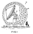
- Figure 1 is an environmental view of a radome 10 which encloses a radio antenna 12.
- Shaped segments 14 which form the radome are comprised of an improved non-woven, electromagnetically transparent asymmetric material of the present invention. Other shapes and forms of radomes may be employed as required by predetermined applications.
- asymmetric and balanced shall refer to the location of the woven support substrate in relation to an associated non-woven layer. That is, in an asymmetric material, a woven substrate shall be placed on one outer face of a non-woven material. In the case of a balanced material, the woven substrate shall be placed on both outer faces of the non-woven effectively creating a three layer sandwich of woven substrate, uniformly distributed fiber batt and woven substrate.
- Improved non-woven electromagnetically transparent asymmetric material 15 ( Figure 2) of the present invention is inert and unaffected by the elements, including sunlight, ozone, temperature extremes, wind, rain and snow.
- the improved non-woven electromagnetically transparent material of the present invention is also a lightweight, high temperature, high strength material which is hydrophobic, and which possesses excellent colour reflectance, electromagnetic transmissivity, a low dielectric constant, and a low loss tangent.
- the material of the present invention reduces maintenance costs, provides a lower cost structural enclosure, does not need to be painted, and has low adhesion and excellent release for snow and ice.
- Figure 2 depicts a supported, non-woven, electromagnetically transparent asymmetric material 15 of the present invention comprising a non-woven batt 16, such as a felt, and a support 18 made of a woven scrim.
- the support 18 may be made of polytetrafluoroethylene, but preferably is expanded, porous polytetrafluoroethylene.
- the non-woven batt 16 can be made of polytetrafluoroethylene staple fiber, i.e. fiber that has not been expanded. However, porous polytetrafluoroethylene is preferred due to its superior electrical transmissivity and low loss characteristics.
- non-woven batt 16 it is preferable to prepare the non-woven batt 16 by the needle punching of staple fibers as generally described in Lauterbach U.S. Pat. No. 2,893,105, which is incorporated herein by reference. However, while needle punching is preferable, any number of other suitable methods may be employed to produce the non-woven batt 16.
- the non-woven batt 16 and the support scrim combination is preferably prepared by taking a loosely, lofty carded web of staple fibers of expanded porous PTFE.
- the web is combined with support scrim 18.
- the woven scrim is placed over one of the webs and the web needle punched with the scrim under it to entangle the staple fibers of the web with the scrim.
- the combination is turned over and a second layer of web is needle punched to the other side of the scrim.
- This needle punch procedure results in simultaneous conversion of the loose webs into needle punched felt or batt, and intimate intercontact of the scrim and staple fibers sufficient to for a unitary coherent material. Continued needle punching will result in more compact, denser, more highly entangled material.
- the felt may contain other fibers. For example, up to about 25% of the felt by weight may comprise fibers of carbon, polyimide, glass, or the like.
- Heavier or lighter scrims may be utilized to support the felt according to the requirements of a particular application. For example, if a composite structure with lower electrical transmission characteristics is required, a lighter scrim would be used. A 1200 denier scrim has proved particularly useful in applications requiring sufficient strength to prevent deformation while under continuous tension, while simultaneously requiring the retention of desired electrical properties.
- the improved non-woven electromagnetically transparent material of the present invention may be made semi-rigid by impregnating the non-woven batt 16 with a thermosetting or thermoplastic resin, either hot melted or soluted.
- the resin in the impregnated non-woven batt 16 may be partially cured with heat to form a dry, flexible sheet in which the resin is in an intermediate cure state, termed "B" stage or "pre-preg” sheet.
- One or more pre-preg sheets comprising the non-woven batt 16 ( Figure 3), or the non-woven batt 16 and the support 18 ( Figure 2), or any combinations thereof, may be stacked together to a desired thickness and laminated together by further curing under heat and pressure to form a laminated composite in which the resin is in a fully-cured state, termed the "C" stage state.
- the B-stage resin of the pre-preg sheet is converted to fully-cured C-stage resin.
- the resultant material is a semi-rigid, non-woven electromagnetically transparent, asymmetric material whose strength prevents deformation while under continuous tension or pressure loading, and whose electrical characteristics are maintained under such loading.
- Expanded porous polytetrafluoroethylene staple weaving fiber 1200 denier monofilament was used to make a woven support scrim.
- the scrim weighed 10.4 ounces per square yard and had a thread count of 30 x 30 threads/inch (MD x CMD).
- Staple fiber of expanded porous PTFE was cut to 3.5 - 4 inch lengths.
- the staple fiber was carded on conventional carding equipment.
- the carded web was placed on the support scrim and needle punched.
- the resulting felt was asymmetric with 100% of the non-woven batt on one side.
- the final weight of the needle felt was 10 ounces per square yard.
- the non-woven batt 16 and the support 18 had the properties outlined in the following Table 1: TABLE 1 Thickness (Inches) .038 Mullen Burst* (Pounds per Square inch) 976 Weight (ounces per square yard) 23.8 Tensile Strength (Lbf/2")(Warp x Fill) 300 x 700 Elongation @ Break (%) 20.6 x 25 *The Mullen's Burst Test was performed in accordance with Federal Std. 191A, Method 5512.
- Plots A, B, C and D represent a material of expanded porous polytetrafluoroethylene felt supported by a 1200 denier scrim made in accordance with the present invention.
- Plot "B” represents a woven fiberglass coated with dispersion of polytetrafluoroethylene.
- Plot "C” represents a commercially available woven fiberglass product coated with a polymer.
- Plot "D” represents a polyvinyl chloride (PVC) sheeting material which is fiberglass reinforced.
- PVC polyvinyl chloride
Abstract
A non-woven electromagnetically transparent material is provided which comprises a non-woven batt (16) and a support scrim (18). The non-woven batt (16) is defined at least in part by fibers of polytetrafluoroethylene. The support scrim (18) is comprised of at least 1200 denier fiber which is interconnected with the non-woven batt (16) to form a unitary coherent structure which is electromagnetically transparent.
Description
- This invention generally relates to supported and unsupported useful non-woven materials for use as support structures in electrically transmissive composites.
- Antennas, such as radar installations and radio telescopes for example, often need a covering structure to protect them from the elements, i.e. sunlight, wind, and moisture. Such a covering structure is referred to as a radome. Preferably, the radome should be airtight.
- A radome is an electromagnetic window which can be manufactured into a desired shape and is conventionally used in ground based systems as well as on aircraft, missiles, and other flight vehicles carrying radar or other electronic transmission equipment. A radome must allow transmission of electromagnetic waves therethrough and also provide the proper structural integrity to protect the electronic transmission apparatus. In the design of a radome, the offsetting goals of structural integrity and electromagnetic transparency compete and depend upon the particular environment in which the radome is to be used.
- One type of radome is an inflatable gas-tight balloon structure which shrouds an antenna. A blower inflates the balloon and spaces the structure away from the antenna so that the antenna may move or rotate freely. A popular form of such covering is a geodesic dome or metal space frame radome, which is formed from many metal (or other structural material) geometric shaped segments, such as triangles, for example, which are covered with an appropriate radio frequency transmitting membrane. Each geometric shaped segment is then affixed to another to form an approximately spherical dome surrounding the radar antenna, which rotates or moves inside the radome. Although positive gas pressure is not required inside this type of metal space frame radome, positive gas pressure may be useful at times, for example, to dislodge snow from the outside of the dome, or to aid in controlling the environment within the dome.
- Conventionally, radome wall structures have included single-layer wall structures of a homogeneous dielectric constant material wherein the thickness of the wall is designed equivalent to an electrical thickness of 1/2 wavelength or some integer multiple thereof. There have also been thin-wall constructions wherein the thickness of the homogeneous dielectric constant material corresponds to a fraction of the wavelength of electromagnetic energy to be passed through the wall. The thin-wall designs have been found to be suitable for use at very low microwave frequencies where the wavelength of the electromagnetic energy is relatively large. However, the thin-wall designs have had insufficient structural integrity for many microwave applications. Although a thick 1/2 wavelength wall design may provide adequate strength and rigidity, such a wall design only allows transmission of electromagnetic energy within a relatively narrow bandwidth to which the radome is tuned, and electrical performance quickly degrades at frequencies above and below the tuned wall thickness.
- In many applications, the radome must allow transmission of electromagnetic energy over a broad bandwidth. The single-layer design using a homogeneous dielectric constant material is problematic because the materials used in their construction are resonant to a given frequency for which it is designed. This causes the transmission and other electrical properties to degrade when the thickness causes an out of resonance condition. The degradation to electromagnetic energy transmission can be reduced by reducing the material thickness of a thin wall radome because the material is reduced to a lower percentage of the wavelength of the energy being passed therethrough, but creates a problem of providing the necessary structural rigidity for desired applications.
- There exist various multi-layer radome constructions which offer enhanced bandwidth and structural capabilities. Some of the same considerations with regard to single-layer radome construction must be considered with respect to a multi-layer construction, such as the associated resonance phenomena which is dependent upon the thickness of the layers of dielectric constant material, for example. In the multi-layer construction, the material thickness can be reduced to thereby reduce the degradation of the transmission capabilities due to the fact that the thickness of the materials are reduced to a lower percentage of the wavelength of the RF energy being passed therethrough. As an example, a conventional "broadband" radome designed to pass frequencies from DC to 18 GHz presents problems in that the radome wall goes in and out of resonance and the wavelength of the upper frequency range is relatively short. Thus, the thicknesses of the layers in a multi-layer construction are normally selected as the minimum thicknesses which meet the structural requirements for a particular application. Presently, radomes can be adequately constructed to meet both the electrical and structural needs in most applications for frequencies between DC and 18 GHz.
- In a typical multi-layer construction for a radome, a mix of low dielectric constant and higher dielectric constant materials is utilized. The low dielectric constant materials are employed for their superior electrical properties, but such materials do not have the compressive and flexural strength and stiffness which is necessary for most applications. The higher dielectric constant materials provide superior mechanical properties, but such materials do not have the electrical properties which are necessary for most applications. Such conventional multi-layer constructions, comprising a mix of both low dielectric constant and higher dielectric constant materials, provide both the structural and electrical needs for applications principally in a range from DC to 18 GHz. Although, the multi-layer radome constructions have advantages over single-layer radome constructions, multi-layer radome constructions also have inherent problems associated with their design. For example, the combination of required dielectric constant values for passing the desired frequency range and still maintaining the required thickness for structural rigidity is somewhat difficult and inefficient with known materials having the desired dielectric constant properties, especially when working with frequencies above 18 GHz.
- Although radome constructions have been found to be suitable over designated frequency ranges of DC to 20 GHz, or a relatively narrow bandwidth of higher frequencies, many applications which are presently being developed require much higher frequencies, and also much greater broadband characteristics. For example, in many applications, the transmission characteristics of the radome are desired to include frequencies of up to 100 GHz, or above. It should be recognized that at extremely high frequencies in the range of 100 GHz, the wavelength of the electromagnetic energy is extremely small and the offsetting electrical and structural needs are in sharp contrast.
- The foregoing illustrates limitations known to exist in present electrically transmissive composites. Thus, it is apparent that it would be advantageous to provide an improved electrically transmissive composite directed to overcoming one or more of the limitations set forth above. Accordingly, a suitable alternative is provided including features more fully disclosed hereinafter.
- An object of the resent invention is to provide an improved electromagnetically transparent material.
- According to the present invention there is provided a non-woven electromagnetically transparent material comprising:
a non-woven batt defined at least in part by fibers of polytetrafluoroethylene which forms a unitary coherent structure which is electromagnetically transparent. - Preferably, a woven support scrim comprised of at least 1200 denier fiber is interconnected with the non-woven batt to form a unitary coherent structure which is electromagnetically transparent material.
- Preferably also, the improved electromagnetically transparent material is provided for various resin systems which may be chemically or thermally cured.
- Embodiments of the present invention will now be described, by way of example, with reference to the accompanying drawings in which:-
- Figure 1 is an environmental view of a radome made from the improved, non-woven, electromagnetically transparent material of the present invention;
- Figure 2 depicts a supported non-woven asymmetric material of the present invention;
- Figure 3 depicts an unsupported non-woven asymmetric material of the present invention; and
- Figure 4 is a graph of Transmission Loss (dB) v. Frequency (GHz) for the material of the present invention, as compared with other conventional materials.
- The improved non-woven electromagnetically transparent material of the present invention employs porous PTFE membranes in at least some of its elements. As the term is used herein, porous polytetrafluoroethylene (PTFE) shall mean a membrane which may be prepared by any number of known processes, for example, by stretching or drawing processes, by papermakng processes, by processes in which filler materials are incorporated with the PTFE resin and which are subsequently removed to leave a porous structure, or by powder sintering processes. Preferably, the porous polytetrafluoroethylene membrane is porous expanded polytetrafluoroethylene membrane having a microstructure of interconnected nodes and fibrils, as described in U.S. Patent Nos. 3,953,566; 4,110,392 and 4,187,390, which are incorporated herein by reference, and which fully describe the preferred material and processes for making them. The porous polytetrafluoroethylene membrane may have a thickness in a range from about 3 to about 1,000 micrometers, preferably in a range of from about 5 to about 100 micrometers, and a pore volume in a range from about 20 to about 98 percent.
- Figure 1 is an environmental view of a
radome 10 which encloses aradio antenna 12. Shapedsegments 14 which form the radome are comprised of an improved non-woven, electromagnetically transparent asymmetric material of the present invention. Other shapes and forms of radomes may be employed as required by predetermined applications. - As the term is used herein, the term asymmetric and balanced shall refer to the location of the woven support substrate in relation to an associated non-woven layer. That is, in an asymmetric material, a woven substrate shall be placed on one outer face of a non-woven material. In the case of a balanced material, the woven substrate shall be placed on both outer faces of the non-woven effectively creating a three layer sandwich of woven substrate, uniformly distributed fiber batt and woven substrate.
- Improved non-woven electromagnetically transparent asymmetric material 15 (Figure 2) of the present invention is inert and unaffected by the elements, including sunlight, ozone, temperature extremes, wind, rain and snow. The improved non-woven electromagnetically transparent material of the present invention is also a lightweight, high temperature, high strength material which is hydrophobic, and which possesses excellent colour reflectance, electromagnetic transmissivity, a low dielectric constant, and a low loss tangent. When used in radome construction, the material of the present invention reduces maintenance costs, provides a lower cost structural enclosure, does not need to be painted, and has low adhesion and excellent release for snow and ice.
- Figure 2 depicts a supported, non-woven, electromagnetically transparent
asymmetric material 15 of the present invention comprising a non-wovenbatt 16, such as a felt, and asupport 18 made of a woven scrim. Thesupport 18 may be made of polytetrafluoroethylene, but preferably is expanded, porous polytetrafluoroethylene. Thenon-woven batt 16 can be made of polytetrafluoroethylene staple fiber, i.e. fiber that has not been expanded. However, porous polytetrafluoroethylene is preferred due to its superior electrical transmissivity and low loss characteristics. - It is preferable to prepare the
non-woven batt 16 by the needle punching of staple fibers as generally described in Lauterbach U.S. Pat. No. 2,893,105, which is incorporated herein by reference. However, while needle punching is preferable, any number of other suitable methods may be employed to produce thenon-woven batt 16. - The
non-woven batt 16 and the support scrim combination is preferably prepared by taking a loosely, lofty carded web of staple fibers of expanded porous PTFE. The web is combined withsupport scrim 18. The woven scrim is placed over one of the webs and the web needle punched with the scrim under it to entangle the staple fibers of the web with the scrim. The combination is turned over and a second layer of web is needle punched to the other side of the scrim. This needle punch procedure results in simultaneous conversion of the loose webs into needle punched felt or batt, and intimate intercontact of the scrim and staple fibers sufficient to for a unitary coherent material. Continued needle punching will result in more compact, denser, more highly entangled material. The felt may contain other fibers. For example, up to about 25% of the felt by weight may comprise fibers of carbon, polyimide, glass, or the like. - Heavier or lighter scrims may be utilized to support the felt according to the requirements of a particular application. For example, if a composite structure with lower electrical transmission characteristics is required, a lighter scrim would be used. A 1200 denier scrim has proved particularly useful in applications requiring sufficient strength to prevent deformation while under continuous tension, while simultaneously requiring the retention of desired electrical properties.
- The improved non-woven electromagnetically transparent material of the present invention may be made semi-rigid by impregnating the
non-woven batt 16 with a thermosetting or thermoplastic resin, either hot melted or soluted. The resin in the impregnatednon-woven batt 16 may be partially cured with heat to form a dry, flexible sheet in which the resin is in an intermediate cure state, termed "B" stage or "pre-preg" sheet. One or more pre-preg sheets comprising the non-woven batt 16 (Figure 3), or thenon-woven batt 16 and the support 18 (Figure 2), or any combinations thereof, may be stacked together to a desired thickness and laminated together by further curing under heat and pressure to form a laminated composite in which the resin is in a fully-cured state, termed the "C" stage state. As should be understood, during the lamination process, the B-stage resin of the pre-preg sheet is converted to fully-cured C-stage resin. The resultant material is a semi-rigid, non-woven electromagnetically transparent, asymmetric material whose strength prevents deformation while under continuous tension or pressure loading, and whose electrical characteristics are maintained under such loading. - Without intending to limit the scope of the present invention, the apparatus and method of production of the present invention may be better understood by referring to the following example:
- Expanded porous polytetrafluoroethylene staple weaving fiber 1200 denier monofilament was used to make a woven support scrim. The scrim weighed 10.4 ounces per square yard and had a thread count of 30 x 30 threads/inch (MD x CMD).
- Staple fiber of expanded porous PTFE was cut to 3.5 - 4 inch lengths. The staple fiber was carded on conventional carding equipment. The carded web was placed on the support scrim and needle punched. The resulting felt was asymmetric with 100% of the non-woven batt on one side. The final weight of the needle felt was 10 ounces per square yard. The
non-woven batt 16 and thesupport 18 had the properties outlined in the following Table 1:TABLE 1 Thickness (Inches) .038 Mullen Burst* (Pounds per Square inch) 976 Weight (ounces per square yard) 23.8 Tensile Strength (Lbf/2")(Warp x Fill) 300 x 700 Elongation @ Break (%) 20.6 x 25 *The Mullen's Burst Test was performed in accordance with Federal Std. 191A, Method 5512. - Electrical transmission and loss data was obtained by subjecting the sample to be tested to a coaxial transmission loss test and noting the transmission loss and loss tangent over a desired frequency range. This test was performed in accordance with ASTM-495-89 (mod.) standard. Briefly, the
material 15 was placed inside a fixture and electronic signals, across a band of frequencies, were transmitted through the sample. The signals were then received and analyzed for clarity. Transmission loss and loss tangent were then calculated. - As best seen by Figure 4, the results of electrical transmission and loss data testing are comparatively graphed as Plots A, B, C and D. Plot "A" represents a material of expanded porous polytetrafluoroethylene felt supported by a 1200 denier scrim made in accordance with the present invention. Plot "B" represents a woven fiberglass coated with dispersion of polytetrafluoroethylene. Plot "C" represents a commercially available woven fiberglass product coated with a polymer. Plot "D" represents a polyvinyl chloride (PVC) sheeting material which is fiberglass reinforced. The following properties were calculated for each material and are summarized in the following Table 2:
Er = dielectric constant
tan X = loss tangenty
't' = coefficient of transmissionTABLE 2 Plot Er tan X t A 1.55 0.0005 0.012 B 2.0 0.0016 0.028 C 2.8 0.012 0.012 D 3.05 0.0052 0.031 - Although a few exemplary embodiments of the present invention have been described in detail above, those skilled in the art readily appreciate that many modifications are possible without materially departing from the novel teachings and advantages which are described herein. Accordingly, all such modifications are intended to be included within the scope of the present invention, as defined by the following claims.
Claims (8)
- A non-woven electromagnetically transparent material comprising:
a non-woven batt defined at least in part by fibers of polytetrafluoroethylene which forms a unitary coherent structure which is electromagnetically transparent. - A material as claimed in claim 1, in which a support scrim of at least 1200 denier is interconnected with the non-woven batt to form a unitary coherent structure which is electromagnetically transparent.
- A material as claimed in claim 1 or 2, wherein the fibers of polytetrafluoroethylene are comprised of expanded polytetrafluoroethylene.
- A material as claimed in any of claims 1 to 3, wherein the non-woven batt further comprises fibers selected from carbon, polyimide or glass.
- A material as claimed in any of claims 1 to 4, wherein the unitary coherent structure is impregnated with a thermosetting resin.
- A material as claimed in any of claims 1 to 4, wherein the unitary coherent structure is impregnated with a thermoplastic resin.
- A material as claimed in claim 5 or 6, wherein the unitary structure is partially cured.
- A material as claimed in claim 5 or 6, wherein the unitary structure is fully cured.
Applications Claiming Priority (2)
| Application Number | Priority Date | Filing Date | Title |
|---|---|---|---|
| US58950496A | 1996-01-22 | 1996-01-22 | |
| US589504 | 2000-06-07 |
Publications (1)
| Publication Number | Publication Date |
|---|---|
| EP0786823A1 true EP0786823A1 (en) | 1997-07-30 |
Family
ID=24358290
Family Applications (1)
| Application Number | Title | Priority Date | Filing Date |
|---|---|---|---|
| EP97300167A Withdrawn EP0786823A1 (en) | 1996-01-22 | 1997-01-13 | Non-woven electro-magnetically transparent material |
Country Status (2)
| Country | Link |
|---|---|
| EP (1) | EP0786823A1 (en) |
| JP (1) | JPH09254291A (en) |
Families Citing this family (2)
| Publication number | Priority date | Publication date | Assignee | Title |
|---|---|---|---|---|
| US7560400B2 (en) * | 2003-07-16 | 2009-07-14 | Raytheon Company | Radome with polyester-polyarylate fibers and a method of making same |
| WO2012119981A1 (en) * | 2011-03-04 | 2012-09-13 | Dsm Ip Assets B.V. | Geodesic radome |
Citations (8)
| Publication number | Priority date | Publication date | Assignee | Title |
|---|---|---|---|---|
| US2893105A (en) | 1954-06-11 | 1959-07-07 | Du Pont | Formation of felt-like products from synthetic filaments |
| US3953566A (en) | 1970-05-21 | 1976-04-27 | W. L. Gore & Associates, Inc. | Process for producing porous products |
| US4110392A (en) | 1976-12-17 | 1978-08-29 | W. L. Gore & Associates, Inc. | Production of porous sintered PTFE products |
| US4291775A (en) * | 1979-11-01 | 1981-09-29 | Cem Corporation | Method and apparatus for improving weighing accuracy |
| US4615933A (en) * | 1984-04-06 | 1986-10-07 | Rogers Corporation | Radome structure and method of manufacture thereof |
| EP0302596A1 (en) * | 1987-08-06 | 1989-02-08 | W.L. Gore & Associates, Inc. | Electromagnetically-transparent laminate |
| US4840838A (en) * | 1988-09-08 | 1989-06-20 | E. I. Du Pont De Nemours And Company | High temperature filter felt |
| US4888234A (en) * | 1986-07-17 | 1989-12-19 | Gates Formed-Fibre Products, Inc. | Formable fiber composite |
-
1997
- 1997-01-13 EP EP97300167A patent/EP0786823A1/en not_active Withdrawn
- 1997-01-22 JP JP911997A patent/JPH09254291A/en active Pending
Patent Citations (9)
| Publication number | Priority date | Publication date | Assignee | Title |
|---|---|---|---|---|
| US2893105A (en) | 1954-06-11 | 1959-07-07 | Du Pont | Formation of felt-like products from synthetic filaments |
| US3953566A (en) | 1970-05-21 | 1976-04-27 | W. L. Gore & Associates, Inc. | Process for producing porous products |
| US4187390A (en) | 1970-05-21 | 1980-02-05 | W. L. Gore & Associates, Inc. | Porous products and process therefor |
| US4110392A (en) | 1976-12-17 | 1978-08-29 | W. L. Gore & Associates, Inc. | Production of porous sintered PTFE products |
| US4291775A (en) * | 1979-11-01 | 1981-09-29 | Cem Corporation | Method and apparatus for improving weighing accuracy |
| US4615933A (en) * | 1984-04-06 | 1986-10-07 | Rogers Corporation | Radome structure and method of manufacture thereof |
| US4888234A (en) * | 1986-07-17 | 1989-12-19 | Gates Formed-Fibre Products, Inc. | Formable fiber composite |
| EP0302596A1 (en) * | 1987-08-06 | 1989-02-08 | W.L. Gore & Associates, Inc. | Electromagnetically-transparent laminate |
| US4840838A (en) * | 1988-09-08 | 1989-06-20 | E. I. Du Pont De Nemours And Company | High temperature filter felt |
Also Published As
| Publication number | Publication date |
|---|---|
| JPH09254291A (en) | 1997-09-30 |
Similar Documents
| Publication | Publication Date | Title |
|---|---|---|
| US8760359B2 (en) | Radome of canape structure | |
| US4726980A (en) | Electromagnetic wave absorbers of silicon carbide fibers | |
| US5408244A (en) | Radome wall design having broadband and mm-wave characteristics | |
| US7463212B1 (en) | Lightweight C-sandwich radome fabrication | |
| US7420523B1 (en) | B-sandwich radome fabrication | |
| US10153546B2 (en) | Composite antiballistic radome walls and methods of making the same | |
| US5686930A (en) | Ultra lightweight thin membrane antenna reflector | |
| US6028565A (en) | W-band and X-band radome wall | |
| AU2008229966B2 (en) | Radome with polyester-polyarylate fibers and a method of making same | |
| KR101952461B1 (en) | Material for radomes and process for making the same | |
| US3453620A (en) | Radome structural composite | |
| WO2013037811A1 (en) | Composite radome wall | |
| KR20060029691A (en) | Rigid radome with polyester-polyarylate fibers and a method of making same | |
| EP0786823A1 (en) | Non-woven electro-magnetically transparent material | |
| CN112968283B (en) | Radome with wave-transmitting, stealth and bulletproof functions and forming process thereof | |
| EP0109186B1 (en) | Antenna | |
| US5264064A (en) | Method and system for radio frequency energy transmission in an imperforate composite structure | |
| JP2000031684A (en) | Radio wave absorber | |
| US11380984B2 (en) | Radome design | |
| Mani | Radome materials | |
| US20200203821A1 (en) | Rugged radome closure utilizing oriented thermoplastics and oriented thermoplastic composites | |
| Jiang et al. | Manufacturing and Characterization of Microstrip Antennas Integrated in 3D Orthogonal Woven Composites | |
| WO1994027109A1 (en) | Anti-radar nets |
Legal Events
| Date | Code | Title | Description |
|---|---|---|---|
| PUAI | Public reference made under article 153(3) epc to a published international application that has entered the european phase |
Free format text: ORIGINAL CODE: 0009012 |
|
| AK | Designated contracting states |
Kind code of ref document: A1 Designated state(s): DE ES FR GB IT NL SE |
|
| STAA | Information on the status of an ep patent application or granted ep patent |
Free format text: STATUS: THE APPLICATION IS DEEMED TO BE WITHDRAWN |
|
| 18D | Application deemed to be withdrawn |
Effective date: 19980131 |