EP0786643A2 - Dispositif d'inspection de la surface du bois pour la détermination des caractéristiques de surface et procédé associé - Google Patents
Dispositif d'inspection de la surface du bois pour la détermination des caractéristiques de surface et procédé associé Download PDFInfo
- Publication number
- EP0786643A2 EP0786643A2 EP97101815A EP97101815A EP0786643A2 EP 0786643 A2 EP0786643 A2 EP 0786643A2 EP 97101815 A EP97101815 A EP 97101815A EP 97101815 A EP97101815 A EP 97101815A EP 0786643 A2 EP0786643 A2 EP 0786643A2
- Authority
- EP
- European Patent Office
- Prior art keywords
- wood
- channel
- channels
- sensor
- beams
- Prior art date
- Legal status (The legal status is an assumption and is not a legal conclusion. Google has not performed a legal analysis and makes no representation as to the accuracy of the status listed.)
- Granted
Links
- 0 C*(C1)=CCC1=C Chemical compound C*(C1)=CCC1=C 0.000 description 1
Images


Classifications
-
- G—PHYSICS
- G01—MEASURING; TESTING
- G01N—INVESTIGATING OR ANALYSING MATERIALS BY DETERMINING THEIR CHEMICAL OR PHYSICAL PROPERTIES
- G01N21/00—Investigating or analysing materials by the use of optical means, i.e. using sub-millimetre waves, infrared, visible or ultraviolet light
- G01N21/84—Systems specially adapted for particular applications
- G01N21/88—Investigating the presence of flaws or contamination
- G01N21/89—Investigating the presence of flaws or contamination in moving material, e.g. running paper or textiles
- G01N21/892—Investigating the presence of flaws or contamination in moving material, e.g. running paper or textiles characterised by the flaw, defect or object feature examined
- G01N21/898—Irregularities in textured or patterned surfaces, e.g. textiles, wood
- G01N21/8986—Wood
Definitions
- the invention relates to a device for inspecting the surface of wood for the purpose of determining surface features, such as cracks or knotholes, consisting of at least one optoelectric sensor, an analog and / or digital electronic and / or optical preprocessing unit and a real-time capable computer, the wood relative to Sensor is movable and an incremental encoder that synchronizes the sensor with the speed of the wood according to the preamble of claim 1 and an inspection method according to claim 11.
- WO 89/07672 discloses a device for optically scanning an object plane by means of a sensor and a light source under difficult atmospheric conditions for the purpose of detecting changing elevations on the plane, in which a division of the emitted light bundle into a scanning and a reference area is known semitransparent mirror and a deflecting optic are used and thus two axially parallel Partial beams are formed which fall on two-quadrant diode or on a CCD matrix sensor and are evaluated there electrically according to the scanning and reference range.
- the device is arranged in a housing which has an exit and an entry window for the light beam bundles, compressed air locks being arranged in front of the windows in order to clean the light source and the sensor from particles contaminating the atmosphere.
- the invention has for its object to provide a method and an apparatus of the type mentioned with which a self-inspection of the surface of wood can be carried out continuously, whereby a number of features such as cracks, knotholes or peaks and depressions are reliably recognized should be and both a color representation and other features are obtained; the device should also be simple and inexpensive.
- the sensor consists of a color laser scanner with at least two beams of different wavelengths and with a receiver with at least two channels, each with an opto-electrical receiving element, the channels by beam splitting, preferably in the direction the surface normal, remitted beam of rays are formed and at least in one of the channels an objective is arranged to generate an intermediate image plane and after the objective within the one channel an optical gradient filter is arranged which is capable of modulating the passing luminous flux onto the associated optoelectric receiving element in a location-dependent manner and the signals of the receiving element of one channel without a gradient filter are converted into a color image in the computer and those of the other channel, the luminous flux of which has been modulated depending on the location, are converted into a profile image of the surface.
- the color laser scanner consists of three individual lasers of different wavelengths ( ⁇ 1, ⁇ 2, ⁇ 3), which are alternately controlled in succession in time-division multiplex with a short pulse duration, for example with 5nsec, the various beams falling successively as short impulses onto a polygon mirror wheel or an elastically suspended micromirror.
- the beams of the three lasers are brought together in a continuous wave by semitransparent mirrors and fall together on a polygon mirror wheel or an elastically suspended micromirror.
- a beam splitter such as splitter mirrors
- the lens for generating an intermediate image plane can either be arranged after the splitter mirror and in front of the optical gradient filter within the channel that has the optical gradient filter, or can be in front of the splitter mirror for both channels. With the exception of the optical gradient filter, both channels are preferably constructed identically.
- the sensor is advantageously arranged in a housing which has a narrow longitudinal slit adapted to the length of the deflection of the laser beam for the exit of the laser beam and a bore as an entrance pupil for the entry of the remitted beam of rays, a device for generating an air overpressure being located within the housing and the air overpressure generates air flows flowing outwards via the longitudinal slot and the entrance pupil. This prevents dust and other atmospheric contamination from entering the housing and deposits on the optics of the device.
- the entrance pupil can have a very small diameter and, together with the lens in front of the divider mirror, can form a needle eye lens.
- the optoelectric receiving elements can be photodiodes, preferably PIN photodiodes.
- the optoelectric receiving element (s) in the channel or in the channels with the optical gradient filter for modulating the luminous flux ( ⁇ ' 2 ) can be position-sensitive optoelectric components, preferably high-speed PSD components.
- the method is characterized in that the sensor consists of a color laser scanner with at least two beams of different wavelengths and with a receiver with at least two channels, each with an optoelectric receiving element, and which splits, preferably in the direction of the surface normal, remitted beams into at least two partial beams and and at least one intermediate image plane is generated in at least one of the channels and the luminous flux of the channel in which the intermediate image plane is generated, is modulated depending on the location for the y deflection of the object point (transport direction of the object) within the partial beam, after which the signals of the receiving element of one channel without location-dependent modulation in the computer into a color image and those of the other channel, the luminous flux of which has been modulated depending on the location is to be converted into a profile picture of the surface.
- the method has the advantage that it allows a completely automatic inspection of the surface of wood continuously, whereby a number of features, such as cracks, knotholes or peaks and depressions, can be reliably recognized and then sorted out.
- a number of features such as cracks, knotholes or peaks and depressions
- both a color representation and other features, such as the profile of the woods are obtained by the method, so that crack formation and its extent can be detected clearly.
- the device is simple and inexpensive and can advantageously be retrofitted to a large number of woodworking machines.
- the position of the image point in the y direction is converted into a ratio of the two luminous fluxes, the ratio being independent of the value of the reflectance.
- the ratio of the luminous flux ( ⁇ ' 1 , ⁇ ' 2 ) can be generated in an analog or digital or analog / digital preprocessing.
- a probability can be calculated from the resulting profile (p profile ) as a measure of the actual occurrence of a searched feature and the features to be detected, which can be described and saved by a clear disturbance of the profile can be found using a convolver with subsequent threshold value comparison.
- the laser beams of the color laser scanner can radiate at an angle of 45 degrees, with a possible deviation of ⁇ 25 degrees, but preferably only ⁇ 15 degrees, from the surface normal of the wooden surface, and the reflected rays can strike the receiving elements in the direction of the surface normal, with a possible deviation of ⁇ 25 degrees, but preferably only ⁇ 15 degrees, which can be position-sensitive optoelectric receiving elements, such as PSD components.
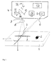
- the senor consists of a laser scanner 5 which generates a laser beam 7 which is guided over the width x of an object 1, preferably a wood 1, by means of a polygon mirror wheel or by means of an elastically suspended micromirror; the wood 1 is moved in the y direction at the speed v y .
- a lens (not shown) in the beam path of the laser scanner 5 ensures a well converging, fine laser beam 7, which thus enables a large depth of field for the scanning.
- An increment encoder (not shown) is coupled on the one hand to the drive machine for the wood and on the other hand to the laser scanner 5.
- the encoder synchronizes the speed of the polygon mirror wheel or the oscillation frequency of the micromirror with the speed of the wood, the synchronization preferably giving square pixels of constant size.
- the transmitter delivers a clock for a downstream computer 13 for processing the received measurement signals.
- the color laser scanner consists of three individual lasers 29, 30, 31 of different wavelengths ⁇ 1, ⁇ 2, ⁇ 3, which are actuated in succession in a time-division multiplex with a short pulse duration, for example with 5nsec, the different beam bundles being successively as short pulses a polygon mirror wheel or an elastically suspended micromirror fall.
- a receiver for receiving the remitted beam 8 of the laser light essentially consists of two channels 11, 12, each with an optoelectric receiving element 19, 20, which are preferably photodiodes, in particular pin photodiodes, wherein the receiving elements can be position-sensitive.
- Laser scanner 5 and receiving channels 11, 12 are arranged in a common housing 4, which has a longitudinal slot 6 for the exit of the laser beam 7.
- the longitudinal slot 6 extends in such a way that the optical axis of the laser is at an angle of 45 degrees to the surface normal of the surface of the wood 1.
- the optical axis of the receiver is preferably perpendicular to the surface of the wood 1, a bore 9 being arranged in the housing 4 as the entrance pupil of the remitted beam 8.
- a lens 15 is arranged behind the entrance pupil 9 within the housing 4, which together with the very small entrance pupil 9 forms a so-called needle eye lens and is used to generate an intermediate image plane.
- a device behind the objective 15 for dividing the remitted ray bundle preferably a divider mirror 10 with a division ratio of 50:50.
- the luminous flux ⁇ ' 1 passing through the splitter mirror 10 reaches the channel 12 and is focused by a lens 16 onto an optoelectric receiving element 20, preferably a pin photodiode.
- the part of the luminous flux ⁇ ' 2 deflected by the divider mirror 10 enters the channel 11, in which there is a gradient filter 18 in the intermediate image plane, which performs a linear change in the luminous flux ⁇ ' 2 as a function of the coordinate y '02 , neglecting Aberrations and vignetting.
- the gradient filter 18, in accordance with the deflection of the laser beam 7 in the y direction, causes the resulting remitted beam 8 to fall locally differently onto the gradient filter 18, which modulates the luminous flux depending on the location.
- the graduated filter 18 there is a lens 17, which in turn focuses the luminous flux ⁇ ' 2 onto an optoelectric receiving element 19, preferably a pin photodiode.
- the channels 11, 12 can, with the exception of the gradient filter 18, be constructed completely identically.
- the bore 9 of the entrance pupil is thus optically symmetrical with the optoelectric receiving elements 19, 20.
- the laser scanner 5 scans the surface of the wood 1 in one plane, preferably at an angle of 45 degrees, a deviation of ⁇ 25 degrees from the surface normal of the wood surface being possible.
- the laser beam 7 scans the x axis of the Cartesian coordinate system xyz. If the surface has cracks (z ⁇ 0), the scanning point of the laser beam 7 moves in the direction of the positive y-axis.
- the selected geometric conditions ensure that a change in the object height ⁇ z causes the scanning point to be deflected in the same way in the y direction ⁇ y. This deflection can be measured directly with the receiver, for which purpose two parameters are of particular interest, namely the reflectance and the depth of the surface disturbance.
- the color image is formed in channel 12.
- the profile of the wood is obtained within the channel 11.
- a particular advantage of the arrangement is the high data rates of approximately 100 MPixel / sec that are typically used.
- the position of the pixel in the y direction is converted by the optical arrangement into a ratio of two light fluxes ⁇ ' 1 and ⁇ ' 2 , which works at a high data rate regardless of the specific value of the remission, ie that dark and light pixels are the same be treated.
- the intermediate image plane is generated, in which the gradient filter 18 is arranged.
- the transmission of the gradient filter 18 is directly proportional to the y-deflection of the object point. Sensitivity fluctuations of the sensor over the scanned area (shading) can be corrected via further gradient filters in both channels in the vicinity of the intermediate image plane or planes.
- the computer 13 is arranged inside the housing 4, which is preferably a real-time computer that processes the two photo streams from the opto-electrical receiving elements 19, 20.
- the photo streams can first be pre-amplified with a transimpedance amplifier with low linearity error.
- the difference between the logarithmic output currents of the photodiodes is therefore independent of the size of the remission of the object point.
- FIG. 1 An electrical block diagram for evaluating the photo currents from the two channels 11 and 12 is shown in FIG.
- the AD-converted output signal of the channel 12 generates the color image from the three wavelengths ⁇ 1, ⁇ 2, ⁇ 3 of the color laser scanner 5.
- the signals from the photodiodes 19, 20 are, as is customary in television technology, amplified with transimpedance amplifiers and can then be clamped at the beginning of the line will. After clamping, both signals are logarithmized in logarithmic operational amplifiers and quantized via an ADC 23.
- the ADU 23 for example 200 MHz / 8bit, is scanned with the clock of the color laser scanner 5.
- a register (RG) 25, 26, 27 is then provided for each wavelength ⁇ 1, ⁇ 2, ⁇ 3, which are each scanned with the clock of the corresponding wavelength ⁇ 1, ⁇ 2, ⁇ 3.
- the color channels ⁇ 1, ⁇ 2, ⁇ 3 are available at the outputs of registers 25, 26, 27, from which a color image of the wooden surface can be obtained.
- the ratio of the output signals or the luminous fluxes ⁇ ' 1 and ⁇ ' 2 can be generated digitally or with the help of an analog preprocessing.
- the advantage of analog preprocessing is the higher dynamic range or higher measuring range of the z coordinate.
- the same result can also be achieved with logarithmic ADC or with ADC divided into several branches.
- the profile is obtained from the two channels 11 and 12 by logarithmers 21, 22 and a logarithmic ADC 24.
- the profile of the wood is then available.
- the coordinate jump in the object plane is placed on the coordinate y max , so that cracks in the material (z> 0) lead to positive y-displacements in the object plane.
- the output signal of the sensor is therefore a logarithmic measure of disturbances in the surface of the material.
- a probability p profile can be calculated from the profile in the preprocessing, which is a measure of the actual occurrence of a sought feature.
- the group that can be described by a clear disturbance in the profile can be found via a convolver with a subsequent threshold value comparison. This includes, for example, cracks, knotholes and surface defects due to worn tools.
- blower 14 Inside the housing 4 there is a blower 14, which generates an overpressure within the housing 4, which generates two air currents which flow out through the slot 6 and the entrance pupil 9 and thereby prevent atmospheric contaminants, such as wood dust, from entering the housing 4 and can settle on the lenses.
- FIG. 4 A further embodiment of the color laser scanner is shown in FIG. 4, which consists of three lasers 29, 30, 31 with discrete different wavelengths ⁇ 1, ⁇ 2, ⁇ 3; an objective 32 is arranged after each laser.
- Two semipermeable Mirrors 33, 34 are arranged so that the beams ⁇ 1 and ⁇ 2 of the lasers 29, 30 deflected by 90 degrees fall onto a polygon mirror wheel 35 or an elastically suspended micromirror, the third beam ⁇ 1 passes through the semitransparent mirrors 33, 34 without being deflected in the direction of the Polygon mirror 35, whereby the three beams ⁇ 1, ⁇ 2, ⁇ 3 are assembled on the same in a continuous line.
- the clock preferably via modulators 36, 37, 38, is fed to the lasers 29, 30, 31 via a line 39; at the same time, the clock is applied to the analog-digital converter 23, 24.
- further holes preferably needle eye lenses, are provided in the housing 4 for the wavelengths ⁇ 2 and ⁇ 3, which are each assigned a simple color channel ⁇ 2 and ⁇ 3; the beam of wavelength ⁇ 1 is further processed as described in FIG. 2 to obtain the profile.
- the laser beams of the color laser scanner 5 radiate at an angle of 45 degrees, a deviation of ⁇ 25 degrees, preferably ⁇ 15 degrees, from the surface normal of the wooden surface being possible;
- the reflected rays preferably fall in the direction of the surface normal, a deviation of ⁇ 25 degrees, preferably ⁇ 15 degrees, also being incident on the receiving elements 19, 20, which are preferably position-sensitive optoelectric receiving elements, such as PSD components .
- the invention is particularly applicable in the wood processing industry, since it allows a completely independent color inspection of the surface of wood continuously, whereby a number of features, such as cracks, knotholes or peaks and depressions, color differences and the profile of the wood, are reliably recognized and can then be sorted out and in particular crack formation can be clearly and extensively recorded.
Landscapes
- Life Sciences & Earth Sciences (AREA)
- Engineering & Computer Science (AREA)
- Wood Science & Technology (AREA)
- Textile Engineering (AREA)
- Chemical & Material Sciences (AREA)
- Health & Medical Sciences (AREA)
- Physics & Mathematics (AREA)
- Analytical Chemistry (AREA)
- Biochemistry (AREA)
- General Health & Medical Sciences (AREA)
- General Physics & Mathematics (AREA)
- Immunology (AREA)
- Pathology (AREA)
- Investigating Materials By The Use Of Optical Means Adapted For Particular Applications (AREA)
- Length Measuring Devices By Optical Means (AREA)
Applications Claiming Priority (2)
| Application Number | Priority Date | Filing Date | Title |
|---|---|---|---|
| DE1996104076 DE19604076C2 (de) | 1996-02-05 | 1996-02-05 | Vorrichtung zur Inspektion der Oberfläche von Holz zwecks Feststellung von Oberflächenmerkmalen und Verfahren hierzu |
| DE19604076 | 1996-02-05 |
Publications (3)
| Publication Number | Publication Date |
|---|---|
| EP0786643A2 true EP0786643A2 (fr) | 1997-07-30 |
| EP0786643A3 EP0786643A3 (fr) | 1998-03-04 |
| EP0786643B1 EP0786643B1 (fr) | 2007-08-22 |
Family
ID=7784526
Family Applications (1)
| Application Number | Title | Priority Date | Filing Date |
|---|---|---|---|
| EP97101815A Expired - Lifetime EP0786643B1 (fr) | 1996-02-05 | 1997-02-05 | Dispositif d'inspection de la surface du bois pour la détermination des caractéristiques de surface et procédé associé |
Country Status (2)
| Country | Link |
|---|---|
| EP (1) | EP0786643B1 (fr) |
| DE (2) | DE19604076C2 (fr) |
Cited By (5)
| Publication number | Priority date | Publication date | Assignee | Title |
|---|---|---|---|---|
| WO1998049545A1 (fr) * | 1997-04-25 | 1998-11-05 | Baumer Optronic Gmbh | Unite de detection, procede et dispositif d'inspection de la surface d'un objet |
| WO2008031621A1 (fr) * | 2006-09-17 | 2008-03-20 | Massen Machine Vision Systems Gmbh | procédé et système d'inspection optique automatique de la surface de bois naturels |
| CN112484657A (zh) * | 2019-08-23 | 2021-03-12 | 松下知识产权经营株式会社 | 激光加工装置、激光加工方法以及修正数据生成方法 |
| CN112986386A (zh) * | 2021-03-24 | 2021-06-18 | 同济大学 | 基于可穿戴式传感器的木结构内部空洞检测装置及方法 |
| CN120721668A (zh) * | 2025-08-18 | 2025-09-30 | 国科大杭州高等研究院 | 一种木制品空间位移激光光谱检测仪 |
Families Citing this family (4)
| Publication number | Priority date | Publication date | Assignee | Title |
|---|---|---|---|---|
| DE10134305B4 (de) * | 2000-07-18 | 2007-01-11 | Leuze Electronic Gmbh & Co Kg | Optoelektronische Vorrichtung |
| DE10063293A1 (de) * | 2000-12-19 | 2002-07-04 | Fraunhofer Ges Forschung | Verfahren und Vorrichtung zur mehrkanaligen Inspektion von Oberflächen im Durchlauf |
| DE102005021649B4 (de) * | 2005-05-06 | 2007-04-12 | Tropf, Hermann | Optische Höhenabtastung einer Oberfläche |
| DE102009007114C5 (de) | 2009-02-02 | 2014-03-13 | Guido Schulte | Verfahren zum Herstellen einer Oberfläche eines Bauteils, dessen Verwendung sowie Oberfläche eines Bauteils |
Family Cites Families (8)
| Publication number | Priority date | Publication date | Assignee | Title |
|---|---|---|---|---|
| JPS5849819B2 (ja) * | 1975-03-18 | 1983-11-07 | コニカ株式会社 | ソウサシキケンサソウチ |
| EP0076866B1 (fr) * | 1981-10-09 | 1985-05-02 | Ibm Deutschland Gmbh | Procédé interpolant de la coupe optique |
| DE3579119D1 (de) * | 1984-11-30 | 1990-09-13 | Kawasaki Steel Co | Verfahren zur bestimmung des oberflaechenglanzes eines koerpers. |
| FR2593599B1 (fr) * | 1986-01-29 | 1991-06-21 | France Etat Ponts Chaussees | Procede et dispositif de determination sans contact du relief d'une surface |
| DE3672163D1 (de) * | 1986-02-22 | 1990-07-26 | Pinsch Gmbh & Co Helmut K | Schnittholz-pruefvorrichtung. |
| ATA42087A (de) * | 1987-02-26 | 1991-09-15 | Isovolta | Verfahren zur skiherstellung |
| IL100655A (en) * | 1991-02-08 | 1994-11-28 | Hughes Aircraft Co | Profile gauge for interferometric laser |
| DE9310554U1 (de) * | 1993-07-15 | 1994-11-17 | Autronic Gesellschaft für Bildverarbeitung und Systeme mbH, 76229 Karlsruhe | Erfassungseinheit für die optronische Oberflächeninspektion |
-
1996
- 1996-02-05 DE DE1996104076 patent/DE19604076C2/de not_active Expired - Fee Related
-
1997
- 1997-02-05 DE DE59712876T patent/DE59712876D1/de not_active Expired - Lifetime
- 1997-02-05 EP EP97101815A patent/EP0786643B1/fr not_active Expired - Lifetime
Cited By (7)
| Publication number | Priority date | Publication date | Assignee | Title |
|---|---|---|---|---|
| WO1998049545A1 (fr) * | 1997-04-25 | 1998-11-05 | Baumer Optronic Gmbh | Unite de detection, procede et dispositif d'inspection de la surface d'un objet |
| US6449036B1 (en) | 1997-04-25 | 2002-09-10 | Baumer Optronic Gmbh | Sensor unit, process and device for inspecting the surface of an object |
| WO2008031621A1 (fr) * | 2006-09-17 | 2008-03-20 | Massen Machine Vision Systems Gmbh | procédé et système d'inspection optique automatique de la surface de bois naturels |
| CN112484657A (zh) * | 2019-08-23 | 2021-03-12 | 松下知识产权经营株式会社 | 激光加工装置、激光加工方法以及修正数据生成方法 |
| CN112484657B (zh) * | 2019-08-23 | 2024-04-12 | 松下知识产权经营株式会社 | 激光加工装置、激光加工方法以及修正数据生成方法 |
| CN112986386A (zh) * | 2021-03-24 | 2021-06-18 | 同济大学 | 基于可穿戴式传感器的木结构内部空洞检测装置及方法 |
| CN120721668A (zh) * | 2025-08-18 | 2025-09-30 | 国科大杭州高等研究院 | 一种木制品空间位移激光光谱检测仪 |
Also Published As
| Publication number | Publication date |
|---|---|
| EP0786643B1 (fr) | 2007-08-22 |
| DE19604076A1 (de) | 1997-08-07 |
| EP0786643A3 (fr) | 1998-03-04 |
| DE59712876D1 (de) | 2007-10-04 |
| DE19604076C2 (de) | 1998-02-19 |
Similar Documents
| Publication | Publication Date | Title |
|---|---|---|
| EP0233970B1 (fr) | Dispositif pour les essais de bois de sciage | |
| DE19717488C2 (de) | Vorrichtung zur Inspektion der Oberfläche von Objekten | |
| EP0787970B1 (fr) | Dispositif d'inspection de la surface du bois pour la détermination des caractéristiques de surface et procédé associé | |
| DE3886043T2 (de) | Methode und system zur bestimmung von oberflächenprofilinformationen. | |
| DE69306244T2 (de) | Verfahren und vorrichtung zur messung der form einer gegenstandsoberfläche | |
| DE2827704C3 (de) | Optische Vorrichtung zur Bestimmung der Lichtaustrittswinkel | |
| EP0943113B1 (fr) | Dispositif pour la presentation polyfocale simultanee du profil superficiel d'objets quelconques | |
| DE3141448A1 (de) | Scanner mit fliegendem lichtpunkt | |
| EP0786643B1 (fr) | Dispositif d'inspection de la surface du bois pour la détermination des caractéristiques de surface et procédé associé | |
| DE2554086A1 (de) | Verfahren zur analyse und/oder zur ortsbestimmung von kanten | |
| EP3658850A1 (fr) | Procédé et dispositif de mesure optique de surfaces au moyen d'un capteur confocal | |
| EP0053730A1 (fr) | Dispositif de reconnaissance d'une clef | |
| DE3534018C2 (fr) | ||
| DE3108344A1 (de) | Laserinspektionssystem | |
| EP2294368B1 (fr) | Procédé et dispositif pour détecter le profil de bord de bouteilles ou de récipients similaires | |
| DE3732149C2 (de) | Verfahren und Vorrichtung zum Charakterisieren einer Genauigkeitseigenschaft einer optischen Linse | |
| EP1262800A2 (fr) | Capteur optoélectronique | |
| DE19643406A1 (de) | Oberflächendetektionssystem für Warenbahnen | |
| EP2883625B1 (fr) | Appareil de tri laser à fibre optique | |
| DE19707225A1 (de) | Lichtabtastvorrichtung | |
| EP1561097B1 (fr) | Dispositif et procede d'enregistrement des caracteristiques de surface d'un objet allonge structure fibreux | |
| DE3703505C2 (fr) | ||
| EP0789832B1 (fr) | Procede et dispositif de verification optique de produits | |
| DE3208041C2 (de) | Verfahren zum Prüfen von ferromagnetischen, magnetisierten Werkstücken | |
| DE19745910C2 (de) | Verfahren und Vorrichtung zum Überprüfen von Hartholzoberflächen auf Risse |
Legal Events
| Date | Code | Title | Description |
|---|---|---|---|
| PUAI | Public reference made under article 153(3) epc to a published international application that has entered the european phase |
Free format text: ORIGINAL CODE: 0009012 |
|
| AK | Designated contracting states |
Kind code of ref document: A2 Designated state(s): CH DE FI FR LI SE |
|
| RIN1 | Information on inventor provided before grant (corrected) |
Inventor name: IHLEFELD, JOACHIM, DR. Inventor name: WENERT, LUTZ Inventor name: WOLLMANN, CHRISTIAN, DR. |
|
| PUAL | Search report despatched |
Free format text: ORIGINAL CODE: 0009013 |
|
| RHK1 | Main classification (correction) |
Ipc: G01B 11/30 |
|
| AK | Designated contracting states |
Kind code of ref document: A3 Designated state(s): AT BE CH DE DK ES FI FR GB IT LI LU NL PT SE |
|
| RAP1 | Party data changed (applicant data changed or rights of an application transferred) |
Owner name: BAUMER OPTRONIC GMBH |
|
| 17P | Request for examination filed |
Effective date: 19980901 |
|
| R17P | Request for examination filed (corrected) |
Effective date: 19980901 |
|
| GRAP | Despatch of communication of intention to grant a patent |
Free format text: ORIGINAL CODE: EPIDOSNIGR1 |
|
| R17P | Request for examination filed (corrected) |
Effective date: 19980901 |
|
| RIC1 | Information provided on ipc code assigned before grant |
Ipc: G01N 21/89 20060101ALI20070221BHEP Ipc: G01B 11/00 20060101ALI20070221BHEP Ipc: G01B 11/24 20060101ALI20070221BHEP Ipc: G01B 11/25 20060101ALI20070221BHEP Ipc: G01B 11/30 20060101AFI20070221BHEP |
|
| GRAS | Grant fee paid |
Free format text: ORIGINAL CODE: EPIDOSNIGR3 |
|
| GRAA | (expected) grant |
Free format text: ORIGINAL CODE: 0009210 |
|
| AK | Designated contracting states |
Kind code of ref document: B1 Designated state(s): CH DE FI FR LI SE |
|
| REG | Reference to a national code |
Ref country code: CH Ref legal event code: EP |
|
| REF | Corresponds to: |
Ref document number: 59712876 Country of ref document: DE Date of ref document: 20071004 Kind code of ref document: P |
|
| REG | Reference to a national code |
Ref country code: SE Ref legal event code: TRGR |
|
| ET | Fr: translation filed | ||
| PG25 | Lapsed in a contracting state [announced via postgrant information from national office to epo] |
Ref country code: FI Free format text: LAPSE BECAUSE OF FAILURE TO SUBMIT A TRANSLATION OF THE DESCRIPTION OR TO PAY THE FEE WITHIN THE PRESCRIBED TIME-LIMIT Effective date: 20070822 |
|
| PLBE | No opposition filed within time limit |
Free format text: ORIGINAL CODE: 0009261 |
|
| STAA | Information on the status of an ep patent application or granted ep patent |
Free format text: STATUS: NO OPPOSITION FILED WITHIN TIME LIMIT |
|
| 26N | No opposition filed |
Effective date: 20080526 |
|
| REG | Reference to a national code |
Ref country code: CH Ref legal event code: PL |
|
| PG25 | Lapsed in a contracting state [announced via postgrant information from national office to epo] |
Ref country code: LI Free format text: LAPSE BECAUSE OF NON-PAYMENT OF DUE FEES Effective date: 20080229 Ref country code: CH Free format text: LAPSE BECAUSE OF NON-PAYMENT OF DUE FEES Effective date: 20080229 |
|
| PGFP | Annual fee paid to national office [announced via postgrant information from national office to epo] |
Ref country code: SE Payment date: 20110225 Year of fee payment: 15 Ref country code: FR Payment date: 20110311 Year of fee payment: 15 |
|
| PGFP | Annual fee paid to national office [announced via postgrant information from national office to epo] |
Ref country code: DE Payment date: 20110428 Year of fee payment: 15 |
|
| PG25 | Lapsed in a contracting state [announced via postgrant information from national office to epo] |
Ref country code: SE Free format text: LAPSE BECAUSE OF NON-PAYMENT OF DUE FEES Effective date: 20120206 |
|
| REG | Reference to a national code |
Ref country code: FR Ref legal event code: ST Effective date: 20121031 |
|
| REG | Reference to a national code |
Ref country code: DE Ref legal event code: R119 Ref document number: 59712876 Country of ref document: DE Effective date: 20120901 |
|
| PG25 | Lapsed in a contracting state [announced via postgrant information from national office to epo] |
Ref country code: FR Free format text: LAPSE BECAUSE OF NON-PAYMENT OF DUE FEES Effective date: 20120229 |
|
| PG25 | Lapsed in a contracting state [announced via postgrant information from national office to epo] |
Ref country code: DE Free format text: LAPSE BECAUSE OF NON-PAYMENT OF DUE FEES Effective date: 20120901 |