EP0786409A1 - Film joining apparatus - Google Patents
Film joining apparatus Download PDFInfo
- Publication number
- EP0786409A1 EP0786409A1 EP95934318A EP95934318A EP0786409A1 EP 0786409 A1 EP0786409 A1 EP 0786409A1 EP 95934318 A EP95934318 A EP 95934318A EP 95934318 A EP95934318 A EP 95934318A EP 0786409 A1 EP0786409 A1 EP 0786409A1
- Authority
- EP
- European Patent Office
- Prior art keywords
- film
- old
- old film
- branch path
- tail end
- Prior art date
- Legal status (The legal status is an assumption and is not a legal conclusion. Google has not performed a legal analysis and makes no representation as to the accuracy of the status listed.)
- Granted
Links
Images


Classifications
-
- B—PERFORMING OPERATIONS; TRANSPORTING
- B65—CONVEYING; PACKING; STORING; HANDLING THIN OR FILAMENTARY MATERIAL
- B65H—HANDLING THIN OR FILAMENTARY MATERIAL, e.g. SHEETS, WEBS, CABLES
- B65H19/00—Changing the web roll
- B65H19/10—Changing the web roll in unwinding mechanisms or in connection with unwinding operations
- B65H19/18—Attaching, e.g. pasting, the replacement web to the expiring web
- B65H19/1842—Attaching, e.g. pasting, the replacement web to the expiring web standing splicing, i.e. the expiring web being stationary during splicing contact
- B65H19/1852—Attaching, e.g. pasting, the replacement web to the expiring web standing splicing, i.e. the expiring web being stationary during splicing contact taking place at a distance from the replacement roll
-
- B—PERFORMING OPERATIONS; TRANSPORTING
- B65—CONVEYING; PACKING; STORING; HANDLING THIN OR FILAMENTARY MATERIAL
- B65H—HANDLING THIN OR FILAMENTARY MATERIAL, e.g. SHEETS, WEBS, CABLES
- B65H2301/00—Handling processes for sheets or webs
- B65H2301/40—Type of handling process
- B65H2301/46—Splicing
- B65H2301/462—Form of splice
- B65H2301/4621—Overlapping article or web portions
- B65H2301/46213—Overlapping article or web portions with L-folded edges sealed together
-
- B—PERFORMING OPERATIONS; TRANSPORTING
- B65—CONVEYING; PACKING; STORING; HANDLING THIN OR FILAMENTARY MATERIAL
- B65H—HANDLING THIN OR FILAMENTARY MATERIAL, e.g. SHEETS, WEBS, CABLES
- B65H2301/00—Handling processes for sheets or webs
- B65H2301/40—Type of handling process
- B65H2301/46—Splicing
- B65H2301/463—Splicing splicing means, i.e. means by which a web end is bound to another web end
- B65H2301/4634—Heat seal splice
-
- B—PERFORMING OPERATIONS; TRANSPORTING
- B65—CONVEYING; PACKING; STORING; HANDLING THIN OR FILAMENTARY MATERIAL
- B65H—HANDLING THIN OR FILAMENTARY MATERIAL, e.g. SHEETS, WEBS, CABLES
- B65H2301/00—Handling processes for sheets or webs
- B65H2301/40—Type of handling process
- B65H2301/46—Splicing
- B65H2301/464—Splicing effecting splice
- B65H2301/46412—Splicing effecting splice by element moving in a direction perpendicular to the running direction of the web
-
- B—PERFORMING OPERATIONS; TRANSPORTING
- B65—CONVEYING; PACKING; STORING; HANDLING THIN OR FILAMENTARY MATERIAL
- B65H—HANDLING THIN OR FILAMENTARY MATERIAL, e.g. SHEETS, WEBS, CABLES
- B65H2406/00—Means using fluid
- B65H2406/10—Means using fluid made only for exhausting gaseous medium
- B65H2406/12—Means using fluid made only for exhausting gaseous medium producing gas blast
-
- B—PERFORMING OPERATIONS; TRANSPORTING
- B65—CONVEYING; PACKING; STORING; HANDLING THIN OR FILAMENTARY MATERIAL
- B65H—HANDLING THIN OR FILAMENTARY MATERIAL, e.g. SHEETS, WEBS, CABLES
- B65H2701/00—Handled material; Storage means
- B65H2701/10—Handled articles or webs
- B65H2701/17—Nature of material
- B65H2701/175—Plastic
- B65H2701/1752—Polymer film
-
- B—PERFORMING OPERATIONS; TRANSPORTING
- B65—CONVEYING; PACKING; STORING; HANDLING THIN OR FILAMENTARY MATERIAL
- B65H—HANDLING THIN OR FILAMENTARY MATERIAL, e.g. SHEETS, WEBS, CABLES
- B65H2801/00—Application field
- B65H2801/81—Packaging machines
Definitions
- the present invention relates to a film joining apparatus.
- a predetermined number of packaging containers which have been discharged from a filling machine after being filled with contents are stacked in a packing pattern, and are wrapped by a heat-shrinkable film such as polyethylene film.
- the film formed in an elongated shape is rolled and is set on a payoff machine as a film roll.
- the film supplied from the payoff machine is continuously fed to a shrink packaging machine.
- the film is cut in the shrink packaging machine when a predetermined amount is used for packaging.
- a new film roll (hereinafter referred to as a "new roll”) is set on the payoff machine, and film is taken out from the new roll. Since the wrapping of packaging containers is continuously performed at the shrink packaging machine, the tail end of a previously used film roll (hereinafter referred to as an “old roll”) is joined with the leading end of the new roll. With this joining operation, film can be continuously supplied to the shrink packaging machine.
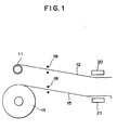
- FIG. 1 is an illustration showing a conventional film joining apparatus in a state before joining films.
- FIG. 2 is an illustration showing the conventional film joining apparatus in a state after joining the films.
- numeral 11 denotes an old roll
- numeral 12 denotes an old film which is taken out from the old roll 11 by an unillustrated payoff machine
- numeral 14 denotes a new roll
- numeral 15 denotes a new film which is taken out from the new roll 14 by an unillustrated payoff machine. While the old film 12 is taken out from the old roll 11, the new roll 14 is set on the payoff machine, as shown in FIG. 1. After that, the leading end of the new film 15 is pulled out.
- Numeral 18 denotes ultrasonic sensors which are disposed along the transport paths of the films 12 and 15 in order to detect the tail ends of the taken-out films 12 and 15.
- Numerals 20 and 21 denote a pair of heaters which are oppositely provided, and adapted to separate and approach each other.
- an unillustrated controller causes the heaters 20 and 21 to approach each other.
- the heaters 20 and 21 nip the old film 12 in the vicinity of the tail end thereof and the leading end of the new film 15, and heat them, thereby fusing and joining them at a joining point a, as shown in FIG. 2. With this operation, the old film 12 and the new film 15 are joined with each other.
- Numeral 12a denotes a residual flap of the old film 12 which is formed on the rear side of the joining point a.
- the controller starts the movement of the heaters 20 and 21 at a timing when the tail end of the old film 12 passes by the ultrasonic sensor 18.
- An object of the present invention is to solve the problems of the conventional film joining apparatus and to provide a film joining apparatus which prevents a residual flap from being formed on the rear side of a joining point when film of an old roll and film of a new roll are joined, thereby eliminating the necessity of stopping a machine in a succeeding stage.
- a film joining apparatus comprises a first transport path along which an old film is transported and onto which a new film whose leading end has been taken out is set, a second transport path which is connected to the first transport path and along which the old film is transported, and a branch path which is branched from the first transport path and the second transport path at a connecting section therebetween.
- the apparatus further comprises a heat fusion unit disposed at the branch path to join the tail end of the old film and the leading end of the new film by heat fusion, and a blower disposed facing the connecting section and adapted to jet an operating gas.
- the leading end of a new film is introduced into the deepest portion of the branch path in advance, and an operating gas is then jetted from the blower. Consequently, an old film is pushed into the branch path due to the pressure of the operating gas, so that the tail end of the old film reaches the deepest portion of the branch path.
- the heat fusion unit then joins the tail end of the old film and the leading end of the new film by heat fusion.
- the heat fusion unit comprises a counter member, a heater disposed to face the counter member with the branch path being located therebetween, and moving means for advancing and retracting the heater.
- the heater holds the old film and the new film in cooperation with the counter member to press and heat them, thereby thermally fusing and joining the old film and the new film, and cuts off a flap portion from the joined films.
- the maximum pressure is generated at a portion where the counter member and the heater lie in the closest proximity to each other, so that the melted resin is pushed toward both sides of the pressed portion due to the maximum pressure. With this operation, the flap portion is cut away from the joined films.
- the counter member is made of an elastic material.
- the surface of the counter member is temporarily retracted due to the pushing force from the heater to form a depression in the surface.
- the counter member restores its original shape as the resin is melted. Accordingly, the counter member can push the melted resin toward both sides of the pressed portion more effectively.
- Still another film joining apparatus further comprises an end sensor for detecting the tail end of an old film, and a controller.
- the controller is provided with stopping means which temporarily stops the transport of an old film at a preset stop timing when the tail end of the old film is detected by the end sensor.
- the stop timing is set such that when an old film is stopped, the distance between the tail end of the old film in the first transport path and the connecting section becomes greater than the distance between the connecting section and a holding unit provided at the branch path.
- Still another film joining apparatus further comprises an end sensor for detecting the tail end of an old film, and a controller.
- the controller is provided with jet start means for starting the jet of the operating gas from the blower at a preset jet start timing when the tail end of the old film is detected by the end sensor.
- the operating gas starts being jetted from the blower at the preset jet start timing when the tail end of the old film is detected by the end sensor.
- the jet start timing is set such that when an old film is stopped, the distance between the tail end of the old film in the first transport path and the connecting section becomes greater than the distance between the connecting section and a holding unit provided at the branch path.
- FIG. 1 is an illustration showing a conventional film joining apparatus in a state before joining films
- FIG. 2 is an illustration showing the conventional film joining apparatus in a state after joining the films
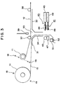
- FIG. 3 is an illustration showing the first state of a film joining apparatus in an embodiment of the present invention
- FIG. 4 is a perspective view of a film supply apparatus in the embodiment of the present invention
- FIG. 5 is a side view of the film supply apparatus in the embodiment of the present invention
- FIG. 6 is an illustration showing the second state of the film joining apparatus in the embodiment of the present invention
- FIG. 7 is an illustration showing the third state of the film joining apparatus in the embodiment of the present invention
- FIG. 8 is an illustration showing the fourth state of the film joining apparatus in the embodiment of the present invention
- FIG. 1 is an illustration showing a conventional film joining apparatus in a state before joining films
- FIG. 2 is an illustration showing the conventional film joining apparatus in a state after joining the films
- FIG. 3 is an illustration showing the first state of a film joining apparatus in an embodiment of the present invention
- FIG. 9 is an illustration showing the fifth state of the film joining apparatus in the embodiment of the present invention.
- FIG. 10 is an illustration for explaining operation of a heat fusion unit used in the embodiment of the present invention.
- FIG. 11 is an illustration of the state of films after being joined by heat fusion in the embodiment of the present invention.
- FIG. 3 is an illustration showing the first state of a film joining apparatus in an embodiment of tie present invention
- FIG. 4 is a perspective view of a film supply apparatus in the embodiment of the present invention
- FIG. 5 is a side view of the film supply apparatus in the embodiment of the present invention.
- numeral 10 denotes a film supply apparatus.
- the film supply apparatus 10 is provided with payoff machines 71 and 72 for supplying a film below the packaging containers, and payoff machines 73 and 74 for supplying a film above the packaging containers.
- New rolls 14 are set on the payoff machines 71 and 73 while old rolls 11 are set on the payoff machines 72 and 74.
- Film joining apparatuses 75 and 76 are disposed under the payoff machines 72 and 74.
- each of the films 12 and 15 is a single layer film made of polyethylene.
- the films 12 and 15 may be made of other resins. While the old film 12 is taken out from the old roll 11, the new roll 14 is set on the payoff machine 71 or 73, and the leading end of the new film 15 is taken out.
- first transport path 31 along which the old film 12 taken out of the old roll 11 is transported and onto which the new film 15 whose leading end has been taken out is set
- second transport path 32 which is connected to the first transport path 31 and along which the old film 12 is transported
- branch path 34 which is branched from a connecting section 33 between the first transport path 31 and the second transport path 32 such that the branch path 34 perpendicularly extends with respect to the transport paths 31 and 32.
- a guide roller 37 is disposed along the first transport path 31 before the connecting section 33 and a guide roller 38 is disposed along the second transport path 32 so as to guide the old film 12.
- An end sensor composed of a photo sensor is disposed in the vicinity of each of the payoff machines 71 - 74.
- the completion of taking out of the old film 12 from the old roll 11 can be detected by detecting the tail end of the old film 12 by the end sensor.
- the end sensor comprises, for example, a photo diode 18 and a photo transistor 19.
- the old film 12 is left on the old roll 11, light emitted by the photo diode 18 is blocked off by the old film 12 so that the light does not reach the photo transistor 19.
- the old film 12 has been mostly or completely taken out from the old roll 11, the light emitted by the photo diode 18 reaches the photo transistor 19. In this way, the completion of taking out of the old film 12 from the old roll 11 can be detected.
- a blower 39 is disposed such that it faces the connecting section 33. Further, a heat fusion unit 40, and a holding unit 41 are provided along the branch path 34.
- the blower 39 has an opening directed to the connecting section 33 and the branch path 34, and jets an operating gas supplied from an unillustrated operating gas supply source.
- the opening of the blower 39 is a slit longer than the width of the old film 12. Therefore, pressure produced by the operating gas acts on the old film 12 over the entire width thereof. Air, inert gas, nitrogen gas or the like can be used as the operating gas in a pressurized or unpressurized state.
- the heat fusion unit 40 is disposed such that it faces the branch path 34.
- the heat fusion unit 40 includes a cylindrical counter roller 43 which has a length greater than the widths of the films 12 and 15 and serves as a counter member, a heater 44 disposed to face the counter roller 43 with the branch path 34 being located therebetween, and a moving cylinder 45 serving as a moving means for advancing and retracting the heater 44.
- the tip of the heater 44 extends in the widthwise direction of the films 12 and 15.
- the holding unit 41 is disposed such that it faces the branch path 34.
- the holding unit 41 includes a counter bar 47 having a length greater than the widths of the films 12 and 15, a film holder 48 disposed to face the counter bar 47 with the branch path 34 being located therebetween, and a moving cylinder 49 for advancing and retracting the film holder 48.
- the tip of the film holder 48 extends in the widthwise direction of the films 12 and 15.
- Numeral 51 denotes a holding frame disposed at the deepest portion of the branch path 34
- numeral 52 denotes a permanent magnet which is attracted by the holding frame 51 to hold the leading end of the new film 15.
- FIG. 6 is an illustration showing the second state of the film joining apparatus in the embodiment of the present invention
- FIG. 7 is an illustration showing the third state of the film joining apparatus in the embodiment of the present invention
- FIG. 8 is an illustration showing the fourth state of the film joining apparatus in the embodiment of the present invention
- FIG. 9 is an illustration showing the fifth state of the film joining apparatus in the embodiment of the present invention.
- the leading end of the new film 15 is led to the deepest portion of the branch path 34 in advance and is held by the holding frame 51 and the permanent magnet 52.
- an operating gas is jetted from the blower 39 at a preset jet start timing, as shown in FIG. 6.
- the old film 12 is pushed into the branch path 34 due to the pressure of the operating gas.
- the taking out of the old film 12 has been already completed and the tail end 12b of the old film 12 has left a roll core 11a. Therefore, as the old film 12 is pushed into the branch path 34, the tail end 12b enters the branch path 34 and reaches the deepest portion of the branch path 34.
- stop means of an unillustrated controller temporarily stops the transport of the old film 12 at the preset stop timing. Also, jet start means of the controller sends a command to the blower 39 to start jetting of the operating gas at a preset jet start timing.
- the timing for stopping the transport of the old film 12 and the timing for starting the jetting of the operating gas are set such that the distance between the tail end 12b of the old film 12 in the first transport path 31 and the connecting section 33 becomes larger than the distance between the connecting section 33 and the holding unit 41 provided at the branch path 34. Consequently, the tail end 12b of the old film 12 can reach the deepest portion of the branch path 34 and a sufficient length of area can be formed for heat fusion.
- the moving cylinder 49 of the holding unit 41 is operated to advance the film holder 48, as shown in FIG. 7.
- the moving cylinder 45 of the heat fusion unit 40 is operated to advance the heater 44.
- the heater 44 is an electric heater.
- the moving cylinder 45 of the heat fusion unit 40 is operated to retract the heater 44 to the original position.
- the new film 15 and the old film 12 fused and joined via a joined portion P1 is pulled by an unillustrated machine in a succeeding stage.
- a flap portion 78 is still pressed against the counter bar 47 by the film holder 48 of the holding unit 41.
- the moving cylinder 49 of the holding unit 41 is operated to retract the film holder 48 to the original position.
- the flap portion 78 is released from the counter bar 47 and is held by the holding frame 51 and the permanent magnet 52.
- FIG. 10 is an illustration for explaining operation of a heat fusion unit used in the embodiment of the present invention
- FIG. 11 is an illustration of the state of films after being joined by heat fusion in the embodiment of the present invention.
- numeral 12 denotes an old film
- numeral 15 denotes a new film
- numeral 43 denotes a cylindrical counter roller serving as a counter member
- numeral 44a denotes a heating member which is disposed to face the counter roller 43 and is advanced toward and retracted from the counter roller 43.
- the heating member 44a is disposed at the tip of the heater 44 (FIG. 3) and comprises a resistance heating element.
- the counter roller 43 has a diameter of 30 mm
- the heating member 44a has a diameter of 0.5 - 1 mm.
- the maximum pressure is generated at a portion P2 where the counter roller 43 and the heating member 44a lie in the closest proximity to each other, so that the melted resin is pushed toward both sides (the side facing the joined films 12 and 15, and the side facing the flap portion 78) due to the pressure from the counter roller 43 and the heating member 44a.
- the counter roller 43 and the heating member 44a finally contact each other. With this operation, the flap portion 78 can be cut off from the films 12 and 15.
- an unillustrated current control circuit is connected to the heating member 44a.
- the current control circuit supplies current to the heating member 44a by using thyristors.
- the flap portion 78 can be cut off from the films 12 and 15. Accordingly, a cutting device is unnecessary.
- the size of the film joining apparatus can be decreased, and costs can be reduced.
- the joined portion P1 can be made flat, as shown in FIG. 11.
- the counter roller 43 may be made of an elastic material.
- the surface of the counter roller 43 is temporarily retracted due to the pushing force from the heater 44 to form a depression in the surface.
- the counter roller 43 restores its original shape as the resin is melted. Accordingly, the counter roller 43 can push the melted resin toward both sides more effectively.
- a flat elastic member may be used in place of the counter roller 43.
- the present invention can be applied to packaging apparatuses for packaging a plurality of stacked packaging containers.
Abstract
Description
- The present invention relates to a film joining apparatus.
- Conventionally, a predetermined number of packaging containers which have been discharged from a filling machine after being filled with contents are stacked in a packing pattern, and are wrapped by a heat-shrinkable film such as polyethylene film.
- The film formed in an elongated shape is rolled and is set on a payoff machine as a film roll. The film supplied from the payoff machine is continuously fed to a shrink packaging machine. The film is cut in the shrink packaging machine when a predetermined amount is used for packaging.
- When a film roll is used up during a continuous packaging operation, a new film roll (hereinafter referred to as a "new roll") is set on the payoff machine, and film is taken out from the new roll. Since the wrapping of packaging containers is continuously performed at the shrink packaging machine, the tail end of a previously used film roll (hereinafter referred to as an "old roll") is joined with the leading end of the new roll. With this joining operation, film can be continuously supplied to the shrink packaging machine.
- FIG. 1 is an illustration showing a conventional film joining apparatus in a state before joining films. FIG. 2 is an illustration showing the conventional film joining apparatus in a state after joining the films.
- In these drawings,
numeral 11 denotes an old roll,numeral 12 denotes an old film which is taken out from theold roll 11 by an unillustrated payoff machine,numeral 14 denotes a new roll,numeral 15 denotes a new film which is taken out from thenew roll 14 by an unillustrated payoff machine. While theold film 12 is taken out from theold roll 11, thenew roll 14 is set on the payoff machine, as shown in FIG. 1. After that, the leading end of thenew film 15 is pulled out. - Numeral 18 denotes ultrasonic sensors which are disposed along the transport paths of the
films films ultrasonic sensor 18 detects the tail end of theold film 12, an unillustrated controller causes theheaters heaters old film 12 in the vicinity of the tail end thereof and the leading end of thenew film 15, and heat them, thereby fusing and joining them at a joining point a, as shown in FIG. 2. With this operation, theold film 12 and thenew film 15 are joined with each other. Numeral 12a denotes a residual flap of theold film 12 which is formed on the rear side of the joining point a. - However, when the
old film 12 and thenew film 15 are joined with each other in the conventional film joining apparatus, the controller starts the movement of theheaters old film 12 passes by theultrasonic sensor 18. - Since the amount of the
old film 12 taken out from theold roll 11 varies depending on the packing pattern in which packaging containers are stacked, it is difficult to position the tail end of theold film 12 between theheaters residual flap 12a of theold film 12 is formed on the rear side of the joining point a. - As a result, when the
new film 15 is taken out from thenew roll 14 without removing theresidual flap 12a, a machine in a succeeding stage will not operate properly. Therefore, an operation for stopping the machine and removing theresidual flap 12a must be performed before theresidual flap 12a enters the machine in the succeeding stage. - An object of the present invention is to solve the problems of the conventional film joining apparatus and to provide a film joining apparatus which prevents a residual flap from being formed on the rear side of a joining point when film of an old roll and film of a new roll are joined, thereby eliminating the necessity of stopping a machine in a succeeding stage.
- To achieve the above object, a film joining apparatus according to the present invention comprises a first transport path along which an old film is transported and onto which a new film whose leading end has been taken out is set, a second transport path which is connected to the first transport path and along which the old film is transported, and a branch path which is branched from the first transport path and the second transport path at a connecting section therebetween.
- The apparatus further comprises a heat fusion unit disposed at the branch path to join the tail end of the old film and the leading end of the new film by heat fusion, and a blower disposed facing the connecting section and adapted to jet an operating gas.
- In the apparatus, the leading end of a new film is introduced into the deepest portion of the branch path in advance, and an operating gas is then jetted from the blower. Consequently, an old film is pushed into the branch path due to the pressure of the operating gas, so that the tail end of the old film reaches the deepest portion of the branch path.
- Accordingly, it is not necessary to insert a pusher or the like into the branch path so as to place the tail end of the old film at the deepest portion of the branch path. This prevents the generation of static electricity in the pusher, the branch path, etc. As a result, the old film and the new film are prevented from adhering to a wall of the branch path or from bending due to static electricity. Accordingly, the heat fusion operation can be carried out smoothly.
- The heat fusion unit then joins the tail end of the old film and the leading end of the new film by heat fusion.
- In another film joining apparatus according to the present invention, the heat fusion unit comprises a counter member, a heater disposed to face the counter member with the branch path being located therebetween, and moving means for advancing and retracting the heater. The heater holds the old film and the new film in cooperation with the counter member to press and heat them, thereby thermally fusing and joining the old film and the new film, and cuts off a flap portion from the joined films.
- At this time, the maximum pressure is generated at a portion where the counter member and the heater lie in the closest proximity to each other, so that the melted resin is pushed toward both sides of the pressed portion due to the maximum pressure. With this operation, the flap portion is cut away from the joined films.
- In still another film joining apparatus according to the present invention, the counter member is made of an elastic material.
- In this case, when the heater is advanced, the surface of the counter member is temporarily retracted due to the pushing force from the heater to form a depression in the surface. However, the counter member restores its original shape as the resin is melted. Accordingly, the counter member can push the melted resin toward both sides of the pressed portion more effectively.
- Still another film joining apparatus according to the present invention further comprises an end sensor for detecting the tail end of an old film, and a controller.
- The controller is provided with stopping means which temporarily stops the transport of an old film at a preset stop timing when the tail end of the old film is detected by the end sensor.
- Therefore, it is possible to temporarily stop the transport of an old film at the preset stop timing when the tail end of the old film is detected by the end sensor.
- In still another film joining apparatus according to the present invention, the stop timing is set such that when an old film is stopped, the distance between the tail end of the old film in the first transport path and the connecting section becomes greater than the distance between the connecting section and a holding unit provided at the branch path.
- Consequently, when the old film is pushed into the branch path due to the pressure of the operating gas from the blower, the tail end of the old film reaches the deepest portion of the branch path and a sufficient length of area can be formed for heat fusion.
- Still another film joining apparatus according to the present invention further comprises an end sensor for detecting the tail end of an old film, and a controller.
- The controller is provided with jet start means for starting the jet of the operating gas from the blower at a preset jet start timing when the tail end of the old film is detected by the end sensor.
- Therefore, the operating gas starts being jetted from the blower at the preset jet start timing when the tail end of the old film is detected by the end sensor.
- In still another film joining apparatus according to the present invention, the jet start timing is set such that when an old film is stopped, the distance between the tail end of the old film in the first transport path and the connecting section becomes greater than the distance between the connecting section and a holding unit provided at the branch path.
- Consequently, when the old film is pushed into the branch path due to the pressure of the operating gas from the blower, the tail end of the old film reaches the deepest portion of the branch path and a sufficient length of area can be formed for heat fusion.
- FIG. 1 is an illustration showing a conventional film joining apparatus in a state before joining films; FIG. 2 is an illustration showing the conventional film joining apparatus in a state after joining the films; FIG. 3 is an illustration showing the first state of a film joining apparatus in an embodiment of the present invention; FIG. 4 is a perspective view of a film supply apparatus in the embodiment of the present invention; FIG. 5 is a side view of the film supply apparatus in the embodiment of the present invention; FIG. 6 is an illustration showing the second state of the film joining apparatus in the embodiment of the present invention; FIG. 7 is an illustration showing the third state of the film joining apparatus in the embodiment of the present invention; FIG. 8 is an illustration showing the fourth state of the film joining apparatus in the embodiment of the present invention; FIG. 9 is an illustration showing the fifth state of the film joining apparatus in the embodiment of the present invention; FIG. 10 is an illustration for explaining operation of a heat fusion unit used in the embodiment of the present invention; and FIG. 11 is an illustration of the state of films after being joined by heat fusion in the embodiment of the present invention.
- The embodiment of the present invention will next be described with reference to the drawings.
- FIG. 3 is an illustration showing the first state of a film joining apparatus in an embodiment of tie present invention, FIG. 4 is a perspective view of a film supply apparatus in the embodiment of the present invention, and FIG. 5 is a side view of the film supply apparatus in the embodiment of the present invention.
- In FIG. 4 and FIG. 5,
numeral 10 denotes a film supply apparatus. In the present embodiment, a predetermined number of unillustrated packaging containers which have been stacked in a packing pattern are wrapped from below and above the packaging containers. Therefore, thefilm supply apparatus 10 is provided withpayoff machines payoff machines New rolls 14 are set on thepayoff machines old rolls 11 are set on thepayoff machines Film joining apparatuses payoff machines - Next, the
film joining apparatuses - In FIG. 3, numeral 11 denotes an old roll, numeral 12 denotes an old film taken out from the
old roll 11 by thepayoff machine 72 or 74 (see FIG. 4), numeral 14 denotes a new roll, numeral 15 denotes a new film taken out from thenew roll 14 by thepayoff machine films films old film 12 is taken out from theold roll 11, thenew roll 14 is set on thepayoff machine new film 15 is taken out. - When the
old film 12 is completely taken out from theold roll 11, the tail end of theold film 12 and the leading end of thenew film 15 are joined with each other by heat fusion. - For this purpose, there are formed a
first transport path 31 along which theold film 12 taken out of theold roll 11 is transported and onto which thenew film 15 whose leading end has been taken out is set, asecond transport path 32 which is connected to thefirst transport path 31 and along which theold film 12 is transported, and abranch path 34 which is branched from a connectingsection 33 between thefirst transport path 31 and thesecond transport path 32 such that thebranch path 34 perpendicularly extends with respect to thetransport paths guide roller 37 is disposed along thefirst transport path 31 before the connectingsection 33 and aguide roller 38 is disposed along thesecond transport path 32 so as to guide theold film 12. - An end sensor composed of a photo sensor is disposed in the vicinity of each of the payoff machines 71 - 74. The completion of taking out of the
old film 12 from theold roll 11 can be detected by detecting the tail end of theold film 12 by the end sensor. The end sensor comprises, for example, aphoto diode 18 and aphoto transistor 19. When theold film 12 is left on theold roll 11, light emitted by thephoto diode 18 is blocked off by theold film 12 so that the light does not reach thephoto transistor 19. When theold film 12 has been mostly or completely taken out from theold roll 11, the light emitted by thephoto diode 18 reaches thephoto transistor 19. In this way, the completion of taking out of theold film 12 from theold roll 11 can be detected. - To join the tail end of the
old film 12 and the leading end of thenew film 15 with each other by heat fusion, ablower 39 is disposed such that it faces the connectingsection 33. Further, aheat fusion unit 40, and a holdingunit 41 are provided along thebranch path 34. - The
blower 39 has an opening directed to the connectingsection 33 and thebranch path 34, and jets an operating gas supplied from an unillustrated operating gas supply source. The opening of theblower 39 is a slit longer than the width of theold film 12. Therefore, pressure produced by the operating gas acts on theold film 12 over the entire width thereof. Air, inert gas, nitrogen gas or the like can be used as the operating gas in a pressurized or unpressurized state. - The
heat fusion unit 40 is disposed such that it faces thebranch path 34. Theheat fusion unit 40 includes acylindrical counter roller 43 which has a length greater than the widths of thefilms heater 44 disposed to face thecounter roller 43 with thebranch path 34 being located therebetween, and a movingcylinder 45 serving as a moving means for advancing and retracting theheater 44. The tip of theheater 44 extends in the widthwise direction of thefilms - The holding
unit 41 is disposed such that it faces thebranch path 34. The holdingunit 41 includes acounter bar 47 having a length greater than the widths of thefilms film holder 48 disposed to face thecounter bar 47 with thebranch path 34 being located therebetween, and a movingcylinder 49 for advancing and retracting thefilm holder 48. The tip of thefilm holder 48 extends in the widthwise direction of thefilms -
Numeral 51 denotes a holding frame disposed at the deepest portion of thebranch path 34, and numeral 52 denotes a permanent magnet which is attracted by the holdingframe 51 to hold the leading end of thenew film 15. - Next, operation of the
film joining apparata - FIG. 6 is an illustration showing the second state of the film joining apparatus in the embodiment of the present invention, FIG. 7 is an illustration showing the third state of the film joining apparatus in the embodiment of the present invention, FIG. 8 is an illustration showing the fourth state of the film joining apparatus in the embodiment of the present invention, and FIG. 9 is an illustration showing the fifth state of the film joining apparatus in the embodiment of the present invention.
- In the first state of the film joining apparatus shown in FIG. 3, the leading end of the
new film 15 is led to the deepest portion of thebranch path 34 in advance and is held by the holdingframe 51 and thepermanent magnet 52. - After that, an operating gas is jetted from the
blower 39 at a preset jet start timing, as shown in FIG. 6. As a result, theold film 12 is pushed into thebranch path 34 due to the pressure of the operating gas. At this time, the taking out of theold film 12 has been already completed and thetail end 12b of theold film 12 has left aroll core 11a. Therefore, as theold film 12 is pushed into thebranch path 34, thetail end 12b enters thebranch path 34 and reaches the deepest portion of thebranch path 34. - Accordingly, it is unnecessary to insert a pusher or the like into the
branch path 34 so as to place thetail end 12b of theold film 12 at the deepest portion of thebranch path 34 or to reciprocate the pusher or the like within thebranch path 34. This prevents the generation of static electricity in the pusher, thebranch path 34, etc. As a result, theold film 12 and thenew film 15 are prevented from adhering to a wall of thebranch path 34 or from bending due to static electricity. Accordingly, the heat fusion operation can be carried out smoothly. - When the
tail end 12b of theold film 12 is detected by the end sensor, stop means of an unillustrated controller temporarily stops the transport of theold film 12 at the preset stop timing. Also, jet start means of the controller sends a command to theblower 39 to start jetting of the operating gas at a preset jet start timing. - The timing for stopping the transport of the
old film 12 and the timing for starting the jetting of the operating gas are set such that the distance between thetail end 12b of theold film 12 in thefirst transport path 31 and the connectingsection 33 becomes larger than the distance between the connectingsection 33 and the holdingunit 41 provided at thebranch path 34. Consequently, thetail end 12b of theold film 12 can reach the deepest portion of thebranch path 34 and a sufficient length of area can be formed for heat fusion. - After that, the moving
cylinder 49 of the holdingunit 41 is operated to advance thefilm holder 48, as shown in FIG. 7. With this operation, thenew film 15 and theold film 12 are pressed against thecounter bar 47 while being superposed on one another. At the same time, or after a short period of time has elapsed, the movingcylinder 45 of theheat fusion unit 40 is operated to advance theheater 44. As a result, thenew film 15 and theold film 12 are pressed against thecounter roller 43 and are heated so that they are joined with each other by heat fusion. At this time, while thenew film 15 and theold film 12 are joined at the fused portion, a flap portion is cut off from the joined films. In the present embodiment, theheater 44 is an electric heater. - Subsequently, as shown in FIG. 8, the moving
cylinder 45 of theheat fusion unit 40 is operated to retract theheater 44 to the original position. As a result, thenew film 15 and theold film 12 fused and joined via a joined portion P1 is pulled by an unillustrated machine in a succeeding stage. At this time, aflap portion 78 is still pressed against thecounter bar 47 by thefilm holder 48 of the holdingunit 41. - After that, as shown in FIG. 9, the moving
cylinder 49 of the holdingunit 41 is operated to retract thefilm holder 48 to the original position. As a result, theflap portion 78 is released from thecounter bar 47 and is held by the holdingframe 51 and thepermanent magnet 52. - Here, heat fusion carried out by the
heat fusion unit 40 will be described. - FIG. 10 is an illustration for explaining operation of a heat fusion unit used in the embodiment of the present invention, and FIG. 11 is an illustration of the state of films after being joined by heat fusion in the embodiment of the present invention.
- In these drawings, numeral 12 denotes an old film, numeral 15 denotes a new film, numeral 43 denotes a cylindrical counter roller serving as a counter member, and numeral 44a denotes a heating member which is disposed to face the
counter roller 43 and is advanced toward and retracted from thecounter roller 43. Theheating member 44a is disposed at the tip of the heater 44 (FIG. 3) and comprises a resistance heating element. In the present embodiment, thecounter roller 43 has a diameter of 30 mm, and theheating member 44a has a diameter of 0.5 - 1 mm. - When the
heater 44 is advanced to press the tail end of theold film 12 and the leading end of thenew film 15 against thecounter roller 43 for pressing these films, and heating is instantaneously performed in this state, resin of the portion nipped by thecounter roller 43 and theheating member 44a is fused so that theold film 12 and thenew film 15 are joined together. A turbulent flow is produced in the fused resin, the joining by heat fusion can be properly performed. - At this time, the maximum pressure is generated at a portion P2 where the
counter roller 43 and theheating member 44a lie in the closest proximity to each other, so that the melted resin is pushed toward both sides (the side facing the joinedfilms counter roller 43 and theheating member 44a. Thecounter roller 43 and theheating member 44a finally contact each other. With this operation, theflap portion 78 can be cut off from thefilms - To instantaneously heat the tail end of the
old film 12 and the leading end of thenew film 15, an unillustrated current control circuit is connected to theheating member 44a. The current control circuit supplies current to theheating member 44a by using thyristors. - As described above, by nipping with pressure and by heating the
films counter roller 43 and theheating member 44a, not only the tail end of theold film 12 and the leading end of thenew film 15 can be joined by heat fusion but also theflap portion 78 can be cut off from thefilms - Furthermore, the
counter roller 43 may be made of an elastic material. In this case, when theheater 44 is advanced, the surface of thecounter roller 43 is temporarily retracted due to the pushing force from theheater 44 to form a depression in the surface. However, thecounter roller 43 restores its original shape as the resin is melted. Accordingly, thecounter roller 43 can push the melted resin toward both sides more effectively. Although thecylindrical counter roller 43 is used in the present embodiment, a flat elastic member may be used in place of thecounter roller 43. - The present invention is not limited to the above-described embodiment. Numerous modifications and variations of the present invention are possible in light of the spirit of the present invention, and they are not excluded from the scope of the present invention.
- The present invention can be applied to packaging apparatuses for packaging a plurality of stacked packaging containers.
Claims (7)
- A film joining apparatus comprising:(a) a first transport path along which an old film is transported and onto which a new film whose leading end has been taken out is set;(b) a second transport path which is connected to said first transport path and along which the old film is transported;(c) a branch path which is branched from said first transport path and said second transport path at a connecting section therebetween;(d) a heat fusion unit disposed at said branch path to join the tail end of the old film and the leading end of the new film by heat fusion; and(e) a blower disposed facing said connecting section and adapted to jet an operating gas.
- A film joining apparatus according to Claim 1, in which(a) said heat fusion unit comprises a counter member, a heater disposed to face said counter member with said branch path being located therebetween, and moving means for advancing and retracting the heater; and(b) said heater nips an old film and a new film in cooperation with said counter member to press and heat them, thereby thermally fusing and joining the old film and the new film, and cuts off a flap portion from the joined films.
- A film joining apparatus according to Claim 1, in which said counter member is made of an elastic material.
- A film joining apparatus according to Claim 1, further comprising an end sensor for detecting the tail end of an old film, and a controller, in which said controller is provided with stopping means which temporarily stops the transport of the old film at a preset stop timing when the tail end of the old film is detected by said end sensor.
- A film joining apparatus according to Claim 4, in which said stop timing is set such that when an old film is stopped, the distance between the tail end of the old film in said first transport path and said connecting section becomes greater than the distance between said connecting section and a holding unit provided at said branch path.
- A film joining apparatus according to Claim 1, further comprising an end sensor for detecting the tail end of an old film, and a controller, in which said controller is provided with jet start means for starting the jet of the operating gas from said blower at a preset jet start timing when the tail end of the old film is detected by said end sensor.
- A film joining apparatus according to Claim 6, in which said jet start timing is set such that when an old film is stopped, the distance between the tail end of the old film in said first transport path and said connecting section becomes greater than the distance between said connecting section and a holding unit provided at said branch path.
Applications Claiming Priority (3)
| Application Number | Priority Date | Filing Date | Title |
|---|---|---|---|
| JP25097594A JP3569004B2 (en) | 1994-10-17 | 1994-10-17 | Film bonding equipment |
| JP250975/94 | 1994-10-17 | ||
| PCT/JP1995/002127 WO1996011845A1 (en) | 1994-10-17 | 1995-10-17 | Film joining apparatus |
Publications (3)
| Publication Number | Publication Date |
|---|---|
| EP0786409A1 true EP0786409A1 (en) | 1997-07-30 |
| EP0786409A4 EP0786409A4 (en) | 1997-12-03 |
| EP0786409B1 EP0786409B1 (en) | 1999-03-10 |
Family
ID=17215815
Family Applications (1)
| Application Number | Title | Priority Date | Filing Date |
|---|---|---|---|
| EP95934318A Expired - Lifetime EP0786409B1 (en) | 1994-10-17 | 1995-10-17 | Film joining apparatus |
Country Status (6)
| Country | Link |
|---|---|
| US (1) | US5863381A (en) |
| EP (1) | EP0786409B1 (en) |
| JP (1) | JP3569004B2 (en) |
| AU (1) | AU3674195A (en) |
| DE (1) | DE69508265T2 (en) |
| WO (1) | WO1996011845A1 (en) |
Cited By (5)
| Publication number | Priority date | Publication date | Assignee | Title |
|---|---|---|---|---|
| EP1528022A1 (en) * | 2003-10-28 | 2005-05-04 | 3M Innovative Properties Company | Adhesive tape splice |
| EP1600412A1 (en) * | 2004-05-26 | 2005-11-30 | Krones AG | Film splicing device |
| AT502291B1 (en) * | 2005-07-29 | 2007-08-15 | Deininger Karl Dipl Ing | Joining apparatus for two webs of material has pre-tensioning mechanism to bring sections into contact by vertical movement relative to draw-in mechanism |
| EP2295355A3 (en) * | 2009-09-10 | 2011-09-28 | Krones AG | Method, device and adhesive tape for splicing label tapes and spliceable label tape |
| WO2015097364A1 (en) * | 2013-12-26 | 2015-07-02 | Spoolex | Method for joining together the ends of two hot-melt items in the form of strips or plies, and end-joining module for implementing said method |
Families Citing this family (23)
| Publication number | Priority date | Publication date | Assignee | Title |
|---|---|---|---|---|
| GB9719104D0 (en) * | 1997-09-10 | 1997-11-12 | Supreme Plastics Group Ltd | Splicing unit and method of splicing |
| IT1304045B1 (en) * | 1998-07-21 | 2001-03-02 | Gd Spa | THERMOPLASTIC TAPE JOINING DEVICE. |
| WO2002024436A1 (en) * | 2000-09-20 | 2002-03-28 | Taisei Lamick Co., Ltd. | Structure, method, and device for splicing laminated films |
| DE60225799T2 (en) * | 2001-06-05 | 2009-04-16 | Ishida Co., Ltd. | POCKET MANUFACTURING AND PACKING MACHINE |
| WO2003050025A1 (en) * | 2001-12-10 | 2003-06-19 | Taisei Lamick Co., Ltd. | Apparatus and method for connecting film |
| DE10301347B4 (en) * | 2003-01-16 | 2013-05-08 | Pester Pac Automation Gmbh | Banding |
| DE102004064000B4 (en) * | 2004-05-26 | 2012-01-05 | Krones Aktiengesellschaft | Film splicing station has splicer for splicing films from first and second unrolling devices at splicing position, holding device for holding film that can be transferred by transfer device in fixed position |
| DE102004032528C5 (en) * | 2004-07-06 | 2012-04-05 | Khs Gmbh | A method of performing a roll change in a supply unit for feeding a sheet-like sheet to a packaging machine or the like processing machine and supply unit for performing this method |
| US6929708B1 (en) * | 2004-11-24 | 2005-08-16 | Bakery Holdings Llc | Film splicing and cutting mechanism |
| WO2007012105A2 (en) * | 2005-07-29 | 2007-02-01 | Karl Deininger | Reel changer |
| JP5329936B2 (en) * | 2008-12-15 | 2013-10-30 | 大森機械工業株式会社 | Film splicer |
| IT1392809B1 (en) * | 2009-02-04 | 2012-03-23 | Goglio Spa | METHOD AND EQUIPMENT TO PERFORM HEAD JOINTS OF A THERMAL-HEATING AND LAMINATED FLEXIBLE LAMINATE SO IT HAS OBTAINED |
| DE102010021732A1 (en) * | 2010-05-27 | 2011-12-01 | Krones Ag | Splicing device and method for splicing a web-like sheet |
| FR2969589B1 (en) * | 2010-12-24 | 2013-10-18 | Additif | DEVICE FOR REINFORCING REINFORCING BOBINE OF STRIP MATERIAL. |
| US20220204198A1 (en) * | 2012-06-18 | 2022-06-30 | TAB Industries, LLC | Exhaust Blower for Orbital Pallet Wrappers |
| KR101340959B1 (en) * | 2013-08-21 | 2013-12-13 | 주식회사 신생테크 | Film recohere apparatus |
| WO2016196896A1 (en) | 2015-06-04 | 2016-12-08 | Douglas Machine Inc. | Auto film splicing assembly with film roll positioner |
| US9956797B2 (en) | 2016-03-02 | 2018-05-01 | OCE Holding B.V. | Web feeding of weak media |
| EP3771309B1 (en) * | 2018-03-21 | 2023-03-15 | Fuji Corporation | Tape auto-loading device and tape linking method therefor |
| CN108675033A (en) * | 2018-04-11 | 2018-10-19 | 浙江华创机电科技有限公司 | A kind of telescopic Film receiving table |
| CN109179029B (en) * | 2018-10-25 | 2020-08-21 | 安徽省临泉县康悦电子科技有限公司 | Capacitor film production tape splicing device capable of improving utilization rate |
| JP6574911B1 (en) * | 2019-01-16 | 2019-09-11 | 大成ラミック株式会社 | Joint tape, packaging film coupling method and coupling apparatus using the same |
| CN114644149B (en) * | 2020-12-18 | 2023-11-21 | 哈尔滨博实自动化股份有限公司 | M-shaped cylindrical film automatic film receiving device |
Citations (4)
| Publication number | Priority date | Publication date | Assignee | Title |
|---|---|---|---|---|
| GB1184591A (en) * | 1967-01-04 | 1970-03-18 | Lerner Machine Company Ltd | Apparatus for Supplying Wrapping Material of Thermoplastic Synthetic Resin to Wrapping Apparatus. |
| DE3203644A1 (en) * | 1981-02-18 | 1982-08-26 | CKD Corp., Komaki, Aichi | Process and apparatus for the automatic splicing or joining of films |
| DE3409702A1 (en) * | 1983-04-06 | 1984-10-11 | Doboy Verpackungsmaschinen Gmbh, 2000 Schenefeld | Process for welding and welding and cutting device for superimposed plastic films |
| DE4013345A1 (en) * | 1990-04-26 | 1991-11-07 | Bielomatik Leuze & Co | Connecting foil webs on packing machines - involves system for complete removal of seam overlaps |
Family Cites Families (16)
| Publication number | Priority date | Publication date | Assignee | Title |
|---|---|---|---|---|
| US3390038A (en) * | 1964-05-12 | 1968-06-25 | Hadley Company Inc | Method and apparatus for trimming and joining the ends of two web lengths |
| US3796625A (en) * | 1972-02-11 | 1974-03-12 | Collins & Alkman Corp | Butt splicing thermoplastic sheeting |
| US3956047A (en) * | 1974-02-01 | 1976-05-11 | Mobil Oil Corporation | Method and apparatus for butt welding thermoplastics sheets and films |
| JPS5951031A (en) * | 1982-09-16 | 1984-03-24 | エービー テトラパック | Automatic connector for continuous package |
| JPH0671955B2 (en) * | 1987-11-25 | 1994-09-14 | シーケーディ株式会社 | Automatic film joining method |
| US4999081A (en) * | 1989-10-11 | 1991-03-12 | Float Machines Inc. | Cutting and heat sealing die assembly |
| IT1241724B (en) * | 1990-06-06 | 1994-02-01 | Ricciarelli Garibaldo S R L | METHOD AND EQUIPMENT FOR THE JOINTING OF ENDS OF WELDABLE FILM TAPES FOR THE FORMATION OF BAGS AND OTHER |
| US5266150A (en) * | 1991-03-08 | 1993-11-30 | Rembrandt Photo Services | Thermocontact welding method and apparatus, and welded product |
| JPH07121730B2 (en) * | 1991-10-10 | 1995-12-25 | 株式会社川島製作所 | Heat-sealing type paper splicing device for packaging machines |
| JP2512392Y2 (en) * | 1991-12-20 | 1996-10-02 | トキワ工業株式会社 | Film splicing equipment for packaging machines |
| JP2578615Y2 (en) * | 1992-09-03 | 1998-08-13 | 新明和工業株式会社 | Packaging machine |
| US5403413A (en) * | 1993-10-01 | 1995-04-04 | Yoshida Kogyo K.K. | Apparatus and method for manufacturing surface fastener bands |
| US5514237A (en) * | 1993-10-05 | 1996-05-07 | The Procter & Gamble Company | Heat splicing of thermoplastic film |
| JP2572196B2 (en) * | 1993-11-25 | 1997-01-16 | バンドー化学株式会社 | Rubber sheet joint method and apparatus |
| JPH08108957A (en) * | 1994-10-07 | 1996-04-30 | Shikoku Kakoki Co Ltd | Tape connecting device |
| US5573617A (en) * | 1995-04-13 | 1996-11-12 | General Motors Corporation | Method of making a two-tone interior vehicle trim panel skin |
-
1994
- 1994-10-17 JP JP25097594A patent/JP3569004B2/en not_active Expired - Lifetime
-
1995
- 1995-10-17 WO PCT/JP1995/002127 patent/WO1996011845A1/en active IP Right Grant
- 1995-10-17 DE DE69508265T patent/DE69508265T2/en not_active Expired - Fee Related
- 1995-10-17 EP EP95934318A patent/EP0786409B1/en not_active Expired - Lifetime
- 1995-10-17 AU AU36741/95A patent/AU3674195A/en not_active Abandoned
- 1995-10-17 US US08/817,530 patent/US5863381A/en not_active Expired - Fee Related
Patent Citations (4)
| Publication number | Priority date | Publication date | Assignee | Title |
|---|---|---|---|---|
| GB1184591A (en) * | 1967-01-04 | 1970-03-18 | Lerner Machine Company Ltd | Apparatus for Supplying Wrapping Material of Thermoplastic Synthetic Resin to Wrapping Apparatus. |
| DE3203644A1 (en) * | 1981-02-18 | 1982-08-26 | CKD Corp., Komaki, Aichi | Process and apparatus for the automatic splicing or joining of films |
| DE3409702A1 (en) * | 1983-04-06 | 1984-10-11 | Doboy Verpackungsmaschinen Gmbh, 2000 Schenefeld | Process for welding and welding and cutting device for superimposed plastic films |
| DE4013345A1 (en) * | 1990-04-26 | 1991-11-07 | Bielomatik Leuze & Co | Connecting foil webs on packing machines - involves system for complete removal of seam overlaps |
Non-Patent Citations (1)
| Title |
|---|
| See also references of WO9611845A1 * |
Cited By (5)
| Publication number | Priority date | Publication date | Assignee | Title |
|---|---|---|---|---|
| EP1528022A1 (en) * | 2003-10-28 | 2005-05-04 | 3M Innovative Properties Company | Adhesive tape splice |
| EP1600412A1 (en) * | 2004-05-26 | 2005-11-30 | Krones AG | Film splicing device |
| AT502291B1 (en) * | 2005-07-29 | 2007-08-15 | Deininger Karl Dipl Ing | Joining apparatus for two webs of material has pre-tensioning mechanism to bring sections into contact by vertical movement relative to draw-in mechanism |
| EP2295355A3 (en) * | 2009-09-10 | 2011-09-28 | Krones AG | Method, device and adhesive tape for splicing label tapes and spliceable label tape |
| WO2015097364A1 (en) * | 2013-12-26 | 2015-07-02 | Spoolex | Method for joining together the ends of two hot-melt items in the form of strips or plies, and end-joining module for implementing said method |
Also Published As
| Publication number | Publication date |
|---|---|
| US5863381A (en) | 1999-01-26 |
| AU3674195A (en) | 1996-05-06 |
| EP0786409B1 (en) | 1999-03-10 |
| EP0786409A4 (en) | 1997-12-03 |
| DE69508265T2 (en) | 1999-07-08 |
| JPH08113213A (en) | 1996-05-07 |
| DE69508265D1 (en) | 1999-04-15 |
| JP3569004B2 (en) | 2004-09-22 |
| WO1996011845A1 (en) | 1996-04-25 |
Similar Documents
| Publication | Publication Date | Title |
|---|---|---|
| EP0786409B1 (en) | Film joining apparatus | |
| JP3713108B2 (en) | Pillow type packaging equipment | |
| US3583888A (en) | Packaging apparatus and method | |
| EP0722414A1 (en) | Method and apparatus for heat splicing thermoplastic film | |
| US5618377A (en) | Film splicer | |
| JPH01294406A (en) | Packaging machine | |
| WO2010010874A1 (en) | Package paper connecting device, package paper connecting method, and packaging apparatus | |
| US3513622A (en) | Packaging of articles | |
| JP2007008558A (en) | Packaging device | |
| US3834971A (en) | Apparatus for butt welding thermoplastics sheets and films | |
| US4696147A (en) | Film tubing device for use in packaging apparatus | |
| JP3681227B2 (en) | Packaging film cutting apparatus and cutting method | |
| KR102235188B1 (en) | Joint tape, method and apparatus for connection of packing film utilizing the same | |
| JP5983712B2 (en) | Wrapping paper connection device, wrapping paper connection method, and packaging device | |
| JP2512392Y2 (en) | Film splicing equipment for packaging machines | |
| JP2005280927A (en) | Film changing device | |
| JP2003026117A (en) | Method and device for deaeration packaging | |
| JP5126951B2 (en) | Packaging film cutting device | |
| JP2517835B2 (en) | Automatic packaging machine | |
| KR101943045B1 (en) | Rolling film processing system | |
| JP3556683B2 (en) | Straw applicator | |
| JP6994026B2 (en) | Equipment and systems for forming creases in thin film materials | |
| DE60003385D1 (en) | Device and method for packaging objects in a continuously fed film | |
| JP3340101B2 (en) | Method and apparatus for sticking a sheet piece to a continuous long base material | |
| JPH08183509A (en) | Automatic continuous packaging machine for printed matter and the like |
Legal Events
| Date | Code | Title | Description |
|---|---|---|---|
| PUAI | Public reference made under article 153(3) epc to a published international application that has entered the european phase |
Free format text: ORIGINAL CODE: 0009012 |
|
| 17P | Request for examination filed |
Effective date: 19970415 |
|
| AK | Designated contracting states |
Kind code of ref document: A1 Designated state(s): DE FR GB IT SE |
|
| A4 | Supplementary search report drawn up and despatched |
Effective date: 19971014 |
|
| AK | Designated contracting states |
Kind code of ref document: A4 Designated state(s): DE FR GB IT SE |
|
| 17Q | First examination report despatched |
Effective date: 19980108 |
|
| GRAG | Despatch of communication of intention to grant |
Free format text: ORIGINAL CODE: EPIDOS AGRA |
|
| GRAG | Despatch of communication of intention to grant |
Free format text: ORIGINAL CODE: EPIDOS AGRA |
|
| GRAH | Despatch of communication of intention to grant a patent |
Free format text: ORIGINAL CODE: EPIDOS IGRA |
|
| GRAH | Despatch of communication of intention to grant a patent |
Free format text: ORIGINAL CODE: EPIDOS IGRA |
|
| GRAH | Despatch of communication of intention to grant a patent |
Free format text: ORIGINAL CODE: EPIDOS IGRA |
|
| GRAH | Despatch of communication of intention to grant a patent |
Free format text: ORIGINAL CODE: EPIDOS IGRA |
|
| GRAA | (expected) grant |
Free format text: ORIGINAL CODE: 0009210 |
|
| AK | Designated contracting states |
Kind code of ref document: B1 Designated state(s): DE FR GB IT SE |
|
| REF | Corresponds to: |
Ref document number: 69508265 Country of ref document: DE Date of ref document: 19990415 |
|
| ET | Fr: translation filed | ||
| PLBE | No opposition filed within time limit |
Free format text: ORIGINAL CODE: 0009261 |
|
| STAA | Information on the status of an ep patent application or granted ep patent |
Free format text: STATUS: NO OPPOSITION FILED WITHIN TIME LIMIT |
|
| 26N | No opposition filed | ||
| REG | Reference to a national code |
Ref country code: GB Ref legal event code: IF02 |
|
| PGFP | Annual fee paid to national office [announced via postgrant information from national office to epo] |
Ref country code: SE Payment date: 20031021 Year of fee payment: 9 |
|
| PG25 | Lapsed in a contracting state [announced via postgrant information from national office to epo] |
Ref country code: SE Free format text: LAPSE BECAUSE OF NON-PAYMENT OF DUE FEES Effective date: 20041018 |
|
| EUG | Se: european patent has lapsed | ||
| PGFP | Annual fee paid to national office [announced via postgrant information from national office to epo] |
Ref country code: DE Payment date: 20081201 Year of fee payment: 14 |
|
| PGFP | Annual fee paid to national office [announced via postgrant information from national office to epo] |
Ref country code: IT Payment date: 20081030 Year of fee payment: 14 |
|
| PGFP | Annual fee paid to national office [announced via postgrant information from national office to epo] |
Ref country code: FR Payment date: 20081018 Year of fee payment: 14 |
|
| PGFP | Annual fee paid to national office [announced via postgrant information from national office to epo] |
Ref country code: GB Payment date: 20081029 Year of fee payment: 14 |
|
| REG | Reference to a national code |
Ref country code: FR Ref legal event code: ST Effective date: 20100630 |
|
| PG25 | Lapsed in a contracting state [announced via postgrant information from national office to epo] |
Ref country code: FR Free format text: LAPSE BECAUSE OF NON-PAYMENT OF DUE FEES Effective date: 20091102 Ref country code: DE Free format text: LAPSE BECAUSE OF NON-PAYMENT OF DUE FEES Effective date: 20100501 |
|
| PG25 | Lapsed in a contracting state [announced via postgrant information from national office to epo] |
Ref country code: GB Free format text: LAPSE BECAUSE OF NON-PAYMENT OF DUE FEES Effective date: 20091017 |
|
| PG25 | Lapsed in a contracting state [announced via postgrant information from national office to epo] |
Ref country code: IT Free format text: LAPSE BECAUSE OF NON-PAYMENT OF DUE FEES Effective date: 20091017 |