EP0786189B1 - Bewegliche auslegerbefestigungsvorrichtung - Google Patents
Bewegliche auslegerbefestigungsvorrichtung Download PDFInfo
- Publication number
- EP0786189B1 EP0786189B1 EP95926652A EP95926652A EP0786189B1 EP 0786189 B1 EP0786189 B1 EP 0786189B1 EP 95926652 A EP95926652 A EP 95926652A EP 95926652 A EP95926652 A EP 95926652A EP 0786189 B1 EP0786189 B1 EP 0786189B1
- Authority
- EP
- European Patent Office
- Prior art keywords
- track
- truck
- boom
- wheels
- microphone
- Prior art date
- Legal status (The legal status is an assumption and is not a legal conclusion. Google has not performed a legal analysis and makes no representation as to the accuracy of the status listed.)
- Expired - Lifetime
Links
Images
Classifications
-
- H—ELECTRICITY
- H04—ELECTRIC COMMUNICATION TECHNIQUE
- H04R—LOUDSPEAKERS, MICROPHONES, GRAMOPHONE PICK-UPS OR LIKE ACOUSTIC ELECTROMECHANICAL TRANSDUCERS; DEAF-AID SETS; PUBLIC ADDRESS SYSTEMS
- H04R1/00—Details of transducers, loudspeakers or microphones
- H04R1/08—Mouthpieces; Microphones; Attachments therefor
Definitions
- the present invention relates generally to the field of recording sound on a television or motion picture production set. More particularly, the present invention relates to replacing a plurality of fixed microphone booms with a single microphone boom on a movable device, while maintaining sound recording quality.
- each microphone is disposed at the end of a long pole or extension like structure referred to those skilled in the art as a "microphone boom.” Each microphone boom is anchored in the catwalk.
- a typical stage for a television program will have several different sets on one large stage.
- a stage may have one set for the kitchen in a house, a neighboring set for the living room, another neighboring set for a bedroom, and yet another neighboring set for a bathroom. Viewing the stage from the front, the sets would be arranged to be adjacent to one another from left to right.
- a typical television stage containing several sets is approximately 24.4 metres (80 feet) long.
- Conventional sound booms were developed during the growth of the motion picture industry in the 1930's and 40's.
- Conventional devices as shown in Patents 2,122,778 and 2,421,437, are typically wheeled tripods or dollys sufficiently large to stably sport a microphone boom and counterbalance.
- Such conventional devices may be suitable for outdoor use, but in the confined space of a movie or television soundstage they are unwieldy. Because of their size, they are wholly unsuitable for mounting on a catwalk above a soundstage.
- a plurality of microphone booms are fixedly mounted in the catwalk above predetermined locations of the set.
- the catwalk is a walkway with railings that is located above the front of the stage.
- the microphone booms are mounted along the railings of the catwalk.
- a typical microphone boom pivots on the mount so that the microphone boom on the end of the boom can be directed down toward the set, just above the actors. Because of the distance between each set, at least one microphone boom is needed for each set, which requires that several microphone booms are used for an entire stage. The use of more than one microphone booms per set maximizes the likelihood that at least one is appropriately positioned at the required location to effectively record sound, no matter where that location is.
- the microphone booms for the entire stage extend from one end of the stage to the other.
- a single microphone boom mounted on a tracked device may be used to record sound over an entire soundstage.
- use of a boom mounted on a conventional tracked device would not yield an acceptable level of sound recording quality.
- the presence of motors and the associated electrical power introduces potential sound interference.
- the light frame and the spring suspension are further potential sound interference sources as well as being inadequate to stably support the weight of a loaded sound boom.
- the track disclosed appears to be too flexible to stably support the weight of a loaded sound boom.
- a movable microphone boom mounting device including a microphone boom pivotally attached via a boom mount on a movable truck that may be rolled along a track, characterised in that:
- the present invention is directed to a movable microphone boom mounting device, which facilitates use of a single or a minimal number of microphone booms, while maintaining a desirable level of sound recording quality.
- the microphone boom mounting device comprises two portions, a track portion and a truck portion which rides along the track portion.
- the truck portion comprises a boom mount for mounting a microphone boom.
- the movable microphone boom mounting device may be mounted above a television or a motion picture production set, in a catwalk located above the set. Lateral and vertical support legs of the movable microphone boom mounting device attach to a railing and a floor of the catwalk, respectively, such that the track portion is secured to the catwalk.
- the track portion is configured in a "T" shape and extends along the floor of the catwalk.
- the truck portion comprises wheels, which flank the horizontal member of the track, contacting the top and bottom surfaces, respectively.
- the truck portion rides along the track portion from one end of the catwalk to the other end.
- a screw brake within the truck portion allows it to be locked into place at any desired position along the track.
- a microphone boom attached to the boom mount on the truck portion can be moved from one end of the track to the other.
- the track portion has overlapping ends which facilitate the connection of several track pieces into one long track that extends along the entire stage, in the catwalk above the stage, such that a single microphone boom can follow the actors between sets on the stage to enable high quality recording of the sound below, for example dialog or the like.
- the boom mount on the truck portion is capable of pivoting to a desired position or angle, and may be locked with a pin into one of several different angles relative to the truck portion.
- the microphone mount may be tilted closer to or away from the set below to facilitate greater ability to position the microphone above the actors on the set below. This is particularly useful when the actors move toward the front of the stage, to a location more directly under the catwalk, where the microphone boom must be tilted down very steeply.
- covers are provided to enclose the open spaces of the truck portion at the sides where the truck portion slides along the track. Dust and other airborne particles are thus kept out of the wheels underneath the truck portion.
- the truck portion also has spacers on the side opposite the screw brake to engage the track during movement to keep the truck portion in an upright position, and also to act as a buffer between the track portion and the side portion of the truck portion when the screw brake is applied.
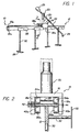
- a movable boom mounting device is shown in the FIG. 1 by the general reference number designation 10.
- the movable boom mounting device comprises two major portions, a track portion 12 and a truck portion 14.
- the track portion 12 is an elongated track which supports the truck portion 14.
- the truck portion 14 slides back and forth along the length of the track portion 12.
- the truck portion 14 is formed from a top portion 16 and side portions 18a, 18b.
- the truck portion also contains a boom mount 20 which is mounted on the top portion 16 of the truck portion 14.
- the boom mount 20 is constructed to accept a microphone boom 22 having a microphone 24 attached at the end thereto.
- a typical microphone boom 22 has a pivot 23 mounted above the boom mount to permit the microphone boom 22 to pivot up and down.
- the microphone boom 22 also has a counterweight portion 25 which balances the weight of the boom on the boom mount 20, to make the microphone boom 22 easier to pivot.
- the typical microphone boom 22 is telescoping, so that the microphone 24 can be extended further away from the boom mount 20.
- the movable boom mounting device 10 is constructed to be located in a catwalk above a television or motion picture production set.
- the catwalk is located above the front of the stage.
- the microphone boom 22 is telescoping so that it can be adjusted such that the microphone 24 extends out and away from the movable boom mounting device 10 and is located above the actors on the set below to permit a high quality recording of sound.
- the pivot 23 on the microphone boom 22 permits the microphone 24 to follow the actors as they walk toward the front of the stage, nearly directly under the catwalk.
- the track portion 12 is mounted to the catwalk by vertical support plates 26 and by lateral support plates 28.
- the vertical support plates 26 mount to the floor of the catwalk.
- the track portion 12 is supported above the vertical support plates 26 by vertical support members 30.
- the lateral support plates 28 are attached to the front railing of the catwalk (facing the stage) in order to provide lateral support to the track portion 12.
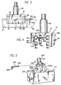
- FIG. 2 is a cross section view of the movable boom mounting device 10 of FIG. 1 taken along the line 2-2.
- the cross sectional view of FIG. 2 illustrates the construction of the track portion 12 and the truck portion 14 of the movable boom mounting device 10.
- the track portion 12 is preferably constructed from two elongated pieces of aluminum which are attached to form a "T" structure. Preferably, the top and lower portions of the track portion 12 are screwed together.
- the lateral support plate 28 (which is attached to the railing of a catwalk) is connected to the bottom portion of the track portion 12 by a lateral support member 32.
- the lateral support plate 28 may be attached to the front railing of a catwalk by any suitable means, such as by screws.
- the lateral support member 32 is attached to the bottom portion of the track portion 12 by any suitable means, but preferably by screws.
- the bottom portion of the track portion 12 extends out and beyond the top portion of the track portion 12, as illustrated at 12a.
- This extended bottom portion 12a contains at least one screw hole 12b, for receiving a screw that would connect an overlapping top portion of an identical, separate track 12 (shown in FIG. 3, discussed below), to the extended bottom portion 12a.
- multiple tracks can be connected together along the entire length of a stage, enabling a microphone boom 22 attached to the truck portion 14 to be located at any position on the entire stage.
- the truck portion 14 slides along the track portion 12 by the support of top wheels 34a, 34b and bottom wheels 36a, 36b.
- the top wheels 34a, 34b are mounted underneath the top portion 16 of the truck portion 14, and are attached by an axle 38 which is connected between the side portions 18a, 18b of the truck portion 14.
- the top wheels 34a, 34b are attached such that they ride along the top surface of the track portion 12, thereby supporting the truck portion 14 above the track portion 12 and allowing the truck portion 14 to slide along the top surface of the track portion 12.
- Wheel 36a is attached to the side portion 18a of the truck portion 14 by an axle 40a.
- Wheel 36b is attached to the side portion 18b of the truck portion 14 by an axle 40b.
- the wheels 36a, 36b are mounted to the truck portion 14 so that they roll along and engage the bottom surface of the top portion of the track portion 12.
- the use of both top wheels 34a, 34b and bottom wheels 36a, 36b allows the truck portion 14 to slide along the length of the track portion 12 while maintaining a high level of stability.
- the wheels 34a, 34b and 36a, 36b can be constructed out of any suitable material. In the preferred embodiment, the wheels are constructed out of polyurethane and are similar to or identical to wheels used on skateboards.
- a portion of the side portion 18b is shown cut away in FIG. 2 to illustrate the attachment of a screw brake 42.
- the screw brake 42 is a screw that is threaded through the side portion 18b such that it can be screwed in to engage the side surface of the top portion of the track portion 12. As the screw brake 42 is screwed in to engage the track portion 12, this causes the truck portion 14 to shift laterally across the track portion 12 such that the side portion 18a comes into a closer contact with the side surface of the top portion of the track portion 12.
- a spacer 44 which acts as a buffer between the side portion 18a and the track portion 12.
- the spacer 44 is preferably made of teflon.
- the spacer 44 has the dual purpose of separating the side portion 18a from the track 12 during movement of the truck portion 14 along the track 12, and of engaging the track 12 as the screw brake 42 is screwed in to attach to the track portion 12. As the screw brake 42 is screwed in to attach to the track portion 12, the screw brake 42 and the spacer 44 engage the track 12 with tighter force, thereby locking the truck portion 14 into a desired position along the track 12.
- the screw brake 42 may be utilized to lock the truck portion 14 into place and to prevent it from inadvertently sliding along the track portion 12.
- FIG. 3 is a side view of the truck portion 14 mounted on the track portion 12.
- the side portion 18b of the truck portion 14 is visible from this view.
- the screw brake 42 is shown located at the same level as the top portion of the track portion 12.
- FIG. 3 also illustrates that the front wheels 34, 36 are matched by identical set of identically-attached wheels 134, 136 at the back end of the truck portion 14.
- the top wheels 34, 134 ride along the top portion of the track portion 12, and the bottom wheels 36, 136 ride along and engage the bottom surface of the top portion of the track portion 12.
- FIG. 3 also illustrates the other end of the track portion 12, which has an overlapping top portion 12c.
- This extending top portion 12c is designed to engage an extending bottom portion 12a shown in FIG. 1 and shown in phantom in FIG. 3.
- the extending top portion 12c has at least one screw hole, preferably two, that lines up with the screw hole 12b located in the extending bottom portion 12a. In this way, a screw 12d will secure one track portion 12 to another track portion 12, so that a single track can be made to extend along the length of the entire stage. Two screws are used in the preferred embodiment because they provide more security in lining-up adjacent track portions.
- FIG. 4 is a perspective view of the truck portion 14.
- FIG. 4 illustrates the truck portion 14 as it is taken off of the track portion 12.
- FIG. 4 illustrates the location and mounting of the front wheels 34a, 34b and 36a, 36b, and rear wheels on one side 134a, 136a.
- FIG. 4 also illustrates the use of two spacers 44a, 44b, both of which are located between the top and bottom wheels to engage the side of the track portion 12. Spacers 44a, 44b ensure that the truck portion 14 is kept straight as it travels along the track portion 12.
- FIG. 5 illustrates an alternative embodiment of the truck portion 214.
- the truck portion 214 of the alternative embodiment of the present invention is similar to the construction of the truck portion 14, however it contains some additional features which will now be described.
- the major added feature of the truck portion 214 is that the boom mount is an adjustable boom mount 220 which pivots about an axle 222.
- the axle 222 is mounted between side plates 224a and 224b.
- Both side plates 224a, 224b contain holes 226 which line up with a hole in the boom mount 220. By lining up the hole in the boom mount 220 with one of the holes 226, a pin 228 may be inserted to lock the boom mount in to a specific position at an angle from the truck portion 214.
- This embodiment permits the boom mount 220 to be tilted more toward the stage below. This is particularly useful when the actors move toward the front of the stage, more directly underneath the catwalk and more directly below the microphone boom, requiring the microphone boom to be tilted more steeply downward. This is also useful in tilting the boom mount 220 back, as the actors move toward the back of the stage, farther away from the microphone boom.
- the pin 228 preferably contains flexible protruding portions 230 to lock the pin in to place once it has been inserted through the holes 226 and the hole through the boom mount 220.
- the pin also preferably includes a ring or handle 232 to facilitate pulling the pin 228 out of the holes 226 and out of the boom mount 220 when it is desired to release the movable boom mount 220 and lock it in to a new angle with respect to the truck portion 214.
- the alternative embodiment of the truck portion 214 also includes additional side panel covers 234 which cover the open sides of the truck portion 214 and enclose it around the "T" structure of the track portion 12.
- the side covers 234 keep out dust particles and other airborne particles from collecting and interfering with the transport mechanism of the wheels underneath the truck portion 214.
Landscapes
- Physics & Mathematics (AREA)
- Engineering & Computer Science (AREA)
- Acoustics & Sound (AREA)
- Signal Processing (AREA)
- Details Of Audible-Bandwidth Transducers (AREA)
- Jib Cranes (AREA)
- Forklifts And Lifting Vehicles (AREA)
Claims (8)
- Bewegliche Auslegerbefestigungsvorrichtung (10) mit einer Fahrschiene (12) und einem Mikrofonausleger (22), der mittels einer Auslegerhalterung (20; 220) an einem beweglichen Rollwagen (14; 214) drehbar befestigt ist, der längs der Fahrschiene (12) verfahrbar ist,
dadurch gekennzeichnet,dass die Fahrschiene (12) einen im Wesentlichen T-förmigen Querschnitt mit einen im Wesentlichen horizontalen, oberen Abschnitt und einem im Wesentlichen vertikalen, unteren Abschnitt aufweist und dass der Rollwagen (14; 214) an der Fahrschiene (12) durch Räder (34a, 34b, 36a, 36b; 134a, 134b, 136a, 136b) gesichert ist, die über und unter dem im Wesentlichen horizontalen, oberen Abschnitt der Fahrschiene (12) drehbar befestigt sind. - Bewegliche Auslegerbefestigungsvorrichtung nach Anspruch 1,
dadurch gekennzeichnet,dass die Räder aus Polyurethan gefertigt sind. - Bewegliche Auslegerbefestigungsvorrichtung nach Anspruch 1 oder 2,
dadurch gekennzeichnet,dass der Rollwagen (214) Abdeckungen (234) aufweist, die die Räder und den durch die Räder gesicherten Rollwagen (12) abdecken, um Schmutzstoffe abzuhalten und sich aus diesen ergebende Störungen zu vermindern. - Bewegliche Auslegerbefestigungsvorrichtung nach Anspruch 1, 2 oder 3,
dadurch gekennzeichnet,dass eine handbetätigte Schraubbremse (42) und Abstandshalter (44a, 44b) reibschlüssig am oberen Abschnitt der Fahrschiene (12) angreifen, um den Rollwagen (14) an einer beliebigen, ausgewählten Stelle längs der Fahrschiene (12) festzulegen, - Bewegliche Auslegerbefestigungsvorrichtung nach Anspruch 4,
dadurch gekennzeichnet,dass die Abstandshalter (44a) und 44(b) aus Polytetrafluorethylen gefertigt sind. - Bewegliche Auslegerbefestigungsvorrichtung nach Anspruch 1,
dadurch gekennzeichnet,dass ein Stift (228) die Drehung der Auslegerhalterung (220) um einen Achsbolzen (222) in Schritten dadurch festlegt, dass der Stift (228) durch zwei Seitenplatten (224a, 224b) durchgeführt wird, die den Achsbolzen (222) und die Auslegerhalterung (220) tragen. - Bewegliche Auslegerbefestigungsvorrichtung nach Anspruch 1,
dadurch gekennzeichnet,dass die Fahrschiene (12) eine Vielzahl von aneinander befestigten Teilen aufweist, wobei jedes Teil ein erstes Ende mit einem überlappenden Oberteil (12c) aufweist, das ein Unterteil (12a) überkragt, und wobei das erste Ende eines Fahrschienenteils in ein zweites Ende eines folgenden Fahrschienenteils greift, das mit seinem Unterteil unter dem genannten Oberteil liegt, und dass ein oder mehrere Befestigungslöcher im Oberteil mit einem oder mehreren entsprechenden Schraublöchern (12b) im Unterteil von ineinander greifenden Fahrschienenenden ausgerichtet sind. - Bewegliche Auslegerbefestigungsvorrichtung nach Anspruch 7,
dadurch gekennzeichnet,dass aufeinander folgende Fahrschienenteile miteinander mittels Schrauben (12d) befestigt sind, die durch aufeinander ausgerichtete Befestigungslöcher und Schraublöcher geführt sind.
Applications Claiming Priority (3)
| Application Number | Priority Date | Filing Date | Title |
|---|---|---|---|
| US27594494A | 1994-07-14 | 1994-07-14 | |
| US275944 | 1994-07-14 | ||
| PCT/US1995/008655 WO1996003011A1 (en) | 1994-07-14 | 1995-07-12 | Movable boom mounting device |
Publications (3)
| Publication Number | Publication Date |
|---|---|
| EP0786189A1 EP0786189A1 (de) | 1997-07-30 |
| EP0786189A4 EP0786189A4 (de) | 1997-07-30 |
| EP0786189B1 true EP0786189B1 (de) | 2000-10-11 |
Family
ID=23054465
Family Applications (1)
| Application Number | Title | Priority Date | Filing Date |
|---|---|---|---|
| EP95926652A Expired - Lifetime EP0786189B1 (de) | 1994-07-14 | 1995-07-12 | Bewegliche auslegerbefestigungsvorrichtung |
Country Status (4)
| Country | Link |
|---|---|
| US (1) | US5757943A (de) |
| EP (1) | EP0786189B1 (de) |
| AU (1) | AU705855B2 (de) |
| WO (1) | WO1996003011A1 (de) |
Families Citing this family (9)
| Publication number | Priority date | Publication date | Assignee | Title |
|---|---|---|---|---|
| US6459801B1 (en) * | 2000-09-27 | 2002-10-01 | Taky Electronics Co., Ltd. | Structure for adjusting position of microphone on microphone mount |
| AT6667U1 (de) * | 2003-03-05 | 2004-01-26 | Richard Dr Oberndorfer | Mikrofon-schlitten |
| US7207532B1 (en) | 2003-10-09 | 2007-04-24 | Roberts Jeffrey A | Boom stand |
| KR100872500B1 (ko) * | 2006-12-26 | 2008-12-05 | 한국항공우주연구원 | 마이크로폰의 안내장치 |
| US8609970B2 (en) | 2008-08-12 | 2013-12-17 | Randall May International Incorporated | Suspended drum microphone system |
| US8063297B2 (en) * | 2008-08-12 | 2011-11-22 | Randall L May | Marimba suspended microphone system |
| US10015571B2 (en) | 2013-12-10 | 2018-07-03 | Randall May International, Inc. | Motorized microphone rail |
| US11856347B1 (en) | 2020-01-16 | 2023-12-26 | David M. Roberts | Speaker stand |
| US11423873B2 (en) * | 2020-10-27 | 2022-08-23 | Toyota Motor Engineering & Manufacturing North America, Inc. | Active noise control for vehicle windshield noise |
Family Cites Families (11)
| Publication number | Priority date | Publication date | Assignee | Title |
|---|---|---|---|---|
| US1975283A (en) * | 1932-12-31 | 1934-10-02 | United Res Corp | Sound recording |
| US2053833A (en) * | 1934-05-12 | 1936-09-08 | Jones Dramin Daniel | Automatic microphone boom |
| US2122778A (en) * | 1936-10-17 | 1938-07-05 | United Res Corp | Microphone boom |
| US2421437A (en) * | 1944-11-10 | 1947-06-03 | Rca Corp | Microphone boom |
| US3431585A (en) * | 1967-02-27 | 1969-03-11 | Lawrence Brothers | Track supports |
| US4475226A (en) * | 1983-10-21 | 1984-10-02 | Donald Blechman | Stereo sound and light track system |
| WO1987003104A1 (en) * | 1985-11-15 | 1987-05-21 | Howell Mary E | Rail mounted camera system |
| JPH06100491B2 (ja) * | 1986-06-06 | 1994-12-12 | 松下電器産業株式会社 | マイクロホン移動装置 |
| US4791674A (en) * | 1987-10-14 | 1988-12-13 | Drever Leslie C | Microphone suspension assembly |
| WO1991015420A1 (en) * | 1990-04-10 | 1991-10-17 | Kamal Benjelloun | Moveable stereo sound system |
| DE69120602T2 (de) * | 1990-05-14 | 1996-11-21 | Gold Star Co | Kamera-Rekorder |
-
1995
- 1995-07-12 WO PCT/US1995/008655 patent/WO1996003011A1/en active IP Right Grant
- 1995-07-12 EP EP95926652A patent/EP0786189B1/de not_active Expired - Lifetime
- 1995-07-12 AU AU30956/95A patent/AU705855B2/en not_active Ceased
-
1996
- 1996-10-23 US US08/735,566 patent/US5757943A/en not_active Expired - Fee Related
Also Published As
| Publication number | Publication date |
|---|---|
| AU3095695A (en) | 1996-02-16 |
| EP0786189A1 (de) | 1997-07-30 |
| WO1996003011A1 (en) | 1996-02-01 |
| AU705855B2 (en) | 1999-06-03 |
| EP0786189A4 (de) | 1997-07-30 |
| US5757943A (en) | 1998-05-26 |
Similar Documents
| Publication | Publication Date | Title |
|---|---|---|
| EP0786189B1 (de) | Bewegliche auslegerbefestigungsvorrichtung | |
| US5974978A (en) | Stabilized lightweight equipment transport system | |
| US6315308B1 (en) | Mobile data/audio/video/interactive presentation cart | |
| CA2092099C (en) | Floor-supported movable wall panel | |
| EP0363417B1 (de) | Gleis und laufkatzensystem | |
| US5737657A (en) | Adjustable platform having a quick release mechanism for use with a camera | |
| US6056450A (en) | Camera support device with telescoping pole and monitor | |
| CA1075085A (en) | Double sash structure | |
| US20050248240A1 (en) | Furniture system enclosing entertainment electronics in range of widths | |
| GB2401784A (en) | A stand having a curved tapering column, a display screen and a floor mount with wheels | |
| US4941578A (en) | High density storage system | |
| CN115918281A (zh) | 显示器支架系统及其使用方法 | |
| US6435421B1 (en) | Dolly track | |
| CA2181896A1 (en) | Swimming pool cleaner discs | |
| US8474097B2 (en) | Roller assembly | |
| US6264001B1 (en) | Scaffolding hanger | |
| US20030210346A1 (en) | Surveillance camera housing | |
| US5806865A (en) | Camera riser | |
| DE69522264D1 (de) | Fernsehempfänger, der eine Videoaufnahme-/Wiedergabe-Einrichtung enthält | |
| JP3038302B2 (ja) | 移動棚装置 | |
| GB9904650D0 (en) | Screen assembly | |
| US20230050471A1 (en) | Rotatable Suspension Rail Background System with Multiple Panels | |
| US11745087B1 (en) | Kit for increasing the ground clearance of a motorized skateboard | |
| JPH0458904A (ja) | Av機器収納ラック | |
| CA2157222A1 (en) | Aerial support platform mechanism with five axes of motion |
Legal Events
| Date | Code | Title | Description |
|---|---|---|---|
| PUAI | Public reference made under article 153(3) epc to a published international application that has entered the european phase |
Free format text: ORIGINAL CODE: 0009012 |
|
| 17P | Request for examination filed |
Effective date: 19970212 |
|
| A4 | Supplementary search report drawn up and despatched |
Effective date: 19970425 |
|
| AK | Designated contracting states |
Kind code of ref document: A4 Designated state(s): FR GB Kind code of ref document: A1 Designated state(s): FR GB |
|
| 17Q | First examination report despatched |
Effective date: 19970901 |
|
| GRAG | Despatch of communication of intention to grant |
Free format text: ORIGINAL CODE: EPIDOS AGRA |
|
| RIC1 | Information provided on ipc code assigned before grant |
Free format text: 6H 04R 1/08 A |
|
| GRAG | Despatch of communication of intention to grant |
Free format text: ORIGINAL CODE: EPIDOS AGRA |
|
| GRAH | Despatch of communication of intention to grant a patent |
Free format text: ORIGINAL CODE: EPIDOS IGRA |
|
| GRAH | Despatch of communication of intention to grant a patent |
Free format text: ORIGINAL CODE: EPIDOS IGRA |
|
| GRAA | (expected) grant |
Free format text: ORIGINAL CODE: 0009210 |
|
| AK | Designated contracting states |
Kind code of ref document: B1 Designated state(s): FR GB |
|
| ET | Fr: translation filed | ||
| PLBE | No opposition filed within time limit |
Free format text: ORIGINAL CODE: 0009261 |
|
| STAA | Information on the status of an ep patent application or granted ep patent |
Free format text: STATUS: NO OPPOSITION FILED WITHIN TIME LIMIT |
|
| 26N | No opposition filed | ||
| REG | Reference to a national code |
Ref country code: GB Ref legal event code: IF02 |
|
| PGFP | Annual fee paid to national office [announced via postgrant information from national office to epo] |
Ref country code: GB Payment date: 20020716 Year of fee payment: 8 |
|
| PGFP | Annual fee paid to national office [announced via postgrant information from national office to epo] |
Ref country code: FR Payment date: 20020723 Year of fee payment: 8 |
|
| PG25 | Lapsed in a contracting state [announced via postgrant information from national office to epo] |
Ref country code: GB Free format text: LAPSE BECAUSE OF NON-PAYMENT OF DUE FEES Effective date: 20030712 |
|
| GBPC | Gb: european patent ceased through non-payment of renewal fee |
Effective date: 20030712 |
|
| PG25 | Lapsed in a contracting state [announced via postgrant information from national office to epo] |
Ref country code: FR Free format text: LAPSE BECAUSE OF NON-PAYMENT OF DUE FEES Effective date: 20040331 |
|
| REG | Reference to a national code |
Ref country code: FR Ref legal event code: ST |