EP0785634A2 - Mobile phone with SIM card - Google Patents
Mobile phone with SIM card Download PDFInfo
- Publication number
- EP0785634A2 EP0785634A2 EP96309177A EP96309177A EP0785634A2 EP 0785634 A2 EP0785634 A2 EP 0785634A2 EP 96309177 A EP96309177 A EP 96309177A EP 96309177 A EP96309177 A EP 96309177A EP 0785634 A2 EP0785634 A2 EP 0785634A2
- Authority
- EP
- European Patent Office
- Prior art keywords
- subscriber identification
- identification module
- phone
- external
- card
- Prior art date
- Legal status (The legal status is an assumption and is not a legal conclusion. Google has not performed a legal analysis and makes no representation as to the accuracy of the status listed.)
- Withdrawn
Links
Images


Classifications
-
- H—ELECTRICITY
- H04—ELECTRIC COMMUNICATION TECHNIQUE
- H04B—TRANSMISSION
- H04B1/00—Details of transmission systems, not covered by a single one of groups H04B3/00 - H04B13/00; Details of transmission systems not characterised by the medium used for transmission
- H04B1/38—Transceivers, i.e. devices in which transmitter and receiver form a structural unit and in which at least one part is used for functions of transmitting and receiving
- H04B1/3816—Mechanical arrangements for accommodating identification devices, e.g. cards or chips; with connectors for programming identification devices
- H04B1/3818—Arrangements for facilitating insertion or removal of identification devices
-
- H—ELECTRICITY
- H04—ELECTRIC COMMUNICATION TECHNIQUE
- H04B—TRANSMISSION
- H04B1/00—Details of transmission systems, not covered by a single one of groups H04B3/00 - H04B13/00; Details of transmission systems not characterised by the medium used for transmission
- H04B1/38—Transceivers, i.e. devices in which transmitter and receiver form a structural unit and in which at least one part is used for functions of transmitting and receiving
- H04B1/3816—Mechanical arrangements for accommodating identification devices, e.g. cards or chips; with connectors for programming identification devices
-
- H—ELECTRICITY
- H04—ELECTRIC COMMUNICATION TECHNIQUE
- H04M—TELEPHONIC COMMUNICATION
- H04M1/00—Substation equipment, e.g. for use by subscribers
- H04M1/02—Constructional features of telephone sets
- H04M1/0202—Portable telephone sets, e.g. cordless phones, mobile phones or bar type handsets
-
- H—ELECTRICITY
- H04—ELECTRIC COMMUNICATION TECHNIQUE
- H04M—TELEPHONIC COMMUNICATION
- H04M1/00—Substation equipment, e.g. for use by subscribers
- H04M1/02—Constructional features of telephone sets
- H04M1/0202—Portable telephone sets, e.g. cordless phones, mobile phones or bar type handsets
- H04M1/0254—Portable telephone sets, e.g. cordless phones, mobile phones or bar type handsets comprising one or a plurality of mechanically detachable modules
-
- H—ELECTRICITY
- H04—ELECTRIC COMMUNICATION TECHNIQUE
- H04W—WIRELESS COMMUNICATION NETWORKS
- H04W48/00—Access restriction; Network selection; Access point selection
- H04W48/18—Selecting a network or a communication service
-
- H—ELECTRICITY
- H04—ELECTRIC COMMUNICATION TECHNIQUE
- H04W—WIRELESS COMMUNICATION NETWORKS
- H04W88/00—Devices specially adapted for wireless communication networks, e.g. terminals, base stations or access point devices
- H04W88/02—Terminal devices
- H04W88/06—Terminal devices adapted for operation in multiple networks or having at least two operational modes, e.g. multi-mode terminals
-
- H—ELECTRICITY
- H04—ELECTRIC COMMUNICATION TECHNIQUE
- H04M—TELEPHONIC COMMUNICATION
- H04M2250/00—Details of telephonic subscriber devices
- H04M2250/14—Details of telephonic subscriber devices including a card reading device
Definitions
- This invention relates to digital mobile phones.
- Such a module which shall hereinafter be referred to as a "subscriber identification module card” is a user replacement module for use by a commercial entity providing a network to ensure that the digital phone is connected to the commercial entities network.
- the actions required mean that the phone has to be turned off so that if one wants to change networks, one then has to go through the additional procedures of closing the phone down, and then starting the phone up again.
- a mobile of the type having a subscriber identification module wherein there are provided at least two subscriber identification modules and switch means accessible to the user and adapted for the user to select one or other of the modules.
- an external holder attachable to an existing mobile digital phone and adapted to take at least two subscriber identification module cards, switch means to provide access to any one of the subscriber identification module cards held in the external holder and means connecting such connected external subscriber identification module card electrically to a subscriber identification module take-off adaptor adapted to be located within an existing internal subscriber identification module card holder of the digital mobile phone.
- the invention can be said to reside in a digital mobile phone of a type having a user removable subscriber identification module card within an internal holder, characterised in that there is within the internal subscriber identification module card holder a take-off card having electrical contacts replicating any subscriber identification module card that would otherwise be therein, and connecting to electrical connections for electrical connection in the phone and having a wire take-off for each subscriber identification module connection, the wire take-off in each case extending to an outside of the body of the mobile phone to an external subscriber identification module card holder, the external subscriber identification module card holder being adapted to hold at least two subscriber identification module cards each having its electrical connections connected to the corresponding wire take-offs connected to the take-off card, and having a switch therewith adapted to change effective active connection from one of the subscriber identification module cards in the external card holder to a second of the subscriber identification module cards in the external card holder.
- this can be said to reside in for a digital mobile phone of a type having a user removable subscriber identification module card within an internal subscriber identification module card holder, a take off card having a wire take-off for each subscriber identification module connection within the holder the wire take-off adapted to extend through to an outside of the body of the mobile phone to an external subscriber identification module card holder attached to the phone casing, the external subscriber identification module card holder being adapted to hold at least two subscriber identification module cards with each having its electrical connections connected to the corresponding wire take offs connected to the wire take-off, and having a switch therewith to change effective active connection of the wire take offs from a first of any subscriber identification module cards in the external card holder to a second or other of any subscriber identification module cards in the external card holder.
- the external subscriber identification module card holder will be adhered in an appropriate way to the body of an existing digital phone and the switch would in preference be a mechanical switch.
- the external card holder there can be additionally provided electronically accessible memory and programmed software in the memory to provide additional functions as far as the digital mobile phone is concerned.
- the wire take-offs are together an integrated flexible circuit board where there is a substrate, a laid conducting track for each circuit on the substrate and an overlay coating.
- the substrate is comprised of polyester plastics material.
- the conducting tracks are copper with gold contact surfaces.
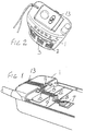
- the phone in this case 1 is a typical of a currently manufactured digital phone having control buttons on its front at 2, microphone at 3, sound output at 4 and a visual display at 5.
- a Subscriber Identification Module which uniquely identifies a subscriber to a provider of a digital communications service.
- a flexible track 6 is formed initially in a planar shape and is assembled so as to have a polyester substrate, a track deposited into an etched channel within the polyester substrate to provide for conduction along the track, and a coating over this again of a polyester plastics material.
- the track also diverts from one linear direction through a diagonal orientation to another lineal direction at 12.
- the switch 13 includes means to hold two Subscriber Identification Modules. By reason of a change in position of the switch 13 from in this case (1) to (2) the effective active electrical connections connected by reason of the take off card 7 will therefore be effectively changed. It will now be seen that by the attachment to the phone 1 of such an electrically conducting track this allows for the user to choose at least one of either of two Subscriber Identification Modules by the simplest of actions. Such an action will not of itself necessarily also require the phone to be switched off and the user can therefore quickly check whether there is service to be provided by one or other of the providers for which the SIM cards are in place.
- the electrical track is of a total thickness of approximately six thousandths of an inch, (this may be within the range of four thousands of an inch to eight thousandths of an inch,) this will not of itself in any cases so far established interfere with any of mechanically interlocking parts that will subsequently have to be reconnected such as a cover plate or a battery connection in an existing mobile phone.
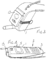
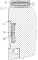
- the phone 14 is of a type which has a separate compartment for the SIM card which can only be opened subsequent to a battery being removed.
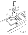
- the compartment shown at 15 is accessible by opening a sliding cover 16 which in Figure 5 for instance and in Figure 7 is shown in the open position.
- a Subscriber Identification Module is intended to be held in a holder at 17 which of itself is pivotally supported at 18.
- a take off card at 18 is inserted in the SIM holder 17 and such then that the electrical contacts at typically 19 will engage against the appropriate electrical connectors of the phone at 20.
- the thin track again of a thickness of approximately six thousandths of an inch, and comprised of two layers of polyester plastics material, is carefully shaped to then be positioned on the back of the holder 17 and then tracked out from the compartment across an edge at 21 to a switch at 22.
- the track in this case is also adhered to an external surface of a body of the phone to keep this in a protected position.
- the track 24 is adhered to the surface of the phone and by reason of its thinness and its material structure such that its substrate and cover is of polyester plastic materials, it is able to follow closely corners of the track with very small radius without fracture.
- the track is adhered to the surface of the phone casing to assist in long term stability and mechanical support.
- an over cover protective coating also adhered across the track and to the casing at both sides of the track.
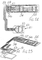
- FIG 9 shows somewhat schematically the way in which the electrical track is located to extend between take off card at 28 and switch at 29.
- the card 28 is held so that its conducting face will electrically connect with connectors such as 30 and then the track of the conducting layers will then follow as shown at 31 for instance until it reaches the switch means 29 where the track itself is folded into a circuitous shape so that respective Subscriber Identification Modules shown at 32 in the one case and 33 in the other will in each case have their oppositely directed electronic parts accessible for electrical connection to the track.
- FIG. 11 A further example of this is in Figure 11 where again track 39 is shown to very closely follow an external shape of the phone body at 40 noting that the general crass hatching is schematic only. In this case again, battery at 41 then can be shown to leave quite clear at 42 any contact or need to squeeze the track 39.
- the track in this case again is of six thousandth of an inch total thickness and the tolerance or clearance between the respective mating members such as the battery.
- the housing will allow for an even larger thickness there between before there is interference with any effective action of the battery being relocated or being placed in position.
- a cover shown at 47 which can be opened to reveal a keypad and also to provide a microphone position.
- a switch means at 48 can be located on the outer surface of the cover 47 and a flexible track at 49 can be allowed to stay clear of being adhered throughout to the cover 47 This allows for a hinging flexible action of the flexible track with a larger radius so that the track which is only six thousandth of an inch thickness can more readily allow for repeated hinging, without undo metal fatigue of the track materials.
- Figure 12 illustrates the fact that in this case, the Subscriber Identification Module is of a larger size such as the size of traditional credit card shown at 50 but here again it works in the same way as those applications previously described.
- Figures 14 and 15 show specifically a typical track comprised of the dual laminate of polyester plastics materials and the inlaid copper track.
- electrical contact points shown typically at 52 and 53 which are in turn, coated with an appropriate long lasting material such as gold or iridium and these are left open for electrical contact purposes.
- contact with respective Subscriber Identification Modules is achieved by folding over the track and accordingly the track itself has two sets of electrical contactors shown at 54 in the one case and 55 in the other. There are breaks in the circuit shown at 56 so that an electrical contactor can variously connect connections say to the take off connectors at 58 in the one case or the connecters at 59 for connection to the contactors at 58 in the other.
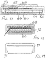
- a track at 60 is folded over generally into an "S" shape so that upper most there are switch connectors at 61, 62 and 63, and such that two Subscriber Identification Modules at 64 and 65 will each fit in a slot shown at 66 so that both an upper and lower face of the two SIM cards will therefore present their electrically open contact surfaces.
- An electrical contact plate at 67 is held under the pressure of a foam pad 68 within switch operative plate 69 and such that respective electrical connections will bridge either between the contacts of 61 and 62 in the one case or 62 and 63 in the other and thereby bring into active connection the module either 64 in the one case or 65 in the other.
- the switch When assembled, the switch has a cross sectional view as shown in Figures 17 and 18 from where it will be seen that the track 60 will be caused to bend tightly back on itself at 73 providing an uppermost surface by which the electrical connections at 67 can then effectively contact and bridge across the appropriate contact surfaces.
Abstract
Description
- This invention relates to digital mobile phones.
- It is conventional in a digital mobile phone that there is a removable subscriber identification module in the form of a card which is fitted into an internal holder.
- Such a module which shall hereinafter be referred to as a "subscriber identification module card" is a user replacement module for use by a commercial entity providing a network to ensure that the digital phone is connected to the commercial entities network.
- It is possible for a user to have the subscriber identification module card of one commercial network provider as well as the subscriber identification module card of its competitor.
- However, in phones currently available, the card is not readily accessible for removal and replacement with an alternate subscriber identification module card.
- It can be achieved but, taking at least one instance, for instance, the currently available Nokia 2110 digital phone, to replace the subscriber identification module card of one network and replace it with another, the battery has to be removed, a first external cover has to be pulled out, and an interlocking bracket must be operated to release the locking position of a pivotal support which is pushed into the release position. It is then still a matter of manipulation to be able to remove the subscriber identification module card from the holder.
- The actions required mean that the phone has to be turned off so that if one wants to change networks, one then has to go through the additional procedures of closing the phone down, and then starting the phone up again.
- At the present time, digital networks are not co-extensive and further, the costs of accessing or using one network as compared to another vary considerably so that there is considerable advantage to an end user to be able to choose the network,
- a) upon being within the range of a particular network or being in a position to better be able to receive a particular signal, and
- b) alternatively that the price of a call from one network may be quite different to the price of another.
- It is currently possible with the same phone to do this but with the effort involved in having to change over subscriber identification module cards, most people will either not consider doing so or will not be bothered in most cases.
- The disadvantage of this is that one network provider which wishes to actively compete with other network providers , might then be at a considerable disadvantage because despite providing best prices, their network might not be quite as extensive and they therefore cannot persuade a phone user to use their network because the decision is made on the basis of both access and cost.
- What I propose is a solution to this problem which will have particular value to a commercial network provider especially if they do not have such an extensive range and it will provide substantial advantages to users because it will enable them to make a better choice without as many of the current implicit difficulties.
- According to one form of this invention there is provided a mobile of the type having a subscriber identification module wherein there are provided at least two subscriber identification modules and switch means accessible to the user and adapted for the user to select one or other of the modules.
- In preference there is proposed that there is an external holder attachable to an existing mobile digital phone and adapted to take at least two subscriber identification module cards, switch means to provide access to any one of the subscriber identification module cards held in the external holder and means connecting such connected external subscriber identification module card electrically to a subscriber identification module take-off adaptor adapted to be located within an existing internal subscriber identification module card holder of the digital mobile phone.
- In a further form the invention can be said to reside in a digital mobile phone of a type having a user removable subscriber identification module card within an internal holder, characterised in that there is within the internal subscriber identification module card holder a take-off card having electrical contacts replicating any subscriber identification module card that would otherwise be therein, and connecting to electrical connections for electrical connection in the phone and having a wire take-off for each subscriber identification module connection, the wire take-off in each case extending to an outside of the body of the mobile phone to an external subscriber identification module card holder, the external subscriber identification module card holder being adapted to hold at least two subscriber identification module cards each having its electrical connections connected to the corresponding wire take-offs connected to the take-off card, and having a switch therewith adapted to change effective active connection from one of the subscriber identification module cards in the external card holder to a second of the subscriber identification module cards in the external card holder.
- In another form of this invention this can be said to reside in for a digital mobile phone of a type having a user removable subscriber identification module card within an internal subscriber identification module card holder, a take off card having a wire take-off for each subscriber identification module connection within the holder the wire take-off adapted to extend through to an outside of the body of the mobile phone to an external subscriber identification module card holder attached to the phone casing, the external subscriber identification module card holder being adapted to hold at least two subscriber identification module cards with each having its electrical connections connected to the corresponding wire take offs connected to the wire take-off, and having a switch therewith to change effective active connection of the wire take offs from a first of any subscriber identification module cards in the external card holder to a second or other of any subscriber identification module cards in the external card holder.
- One of the difficulties with such an arrangement, however, is the question of how one provides such electrical connections from the internal parts of the phone to an external subscriber identification module card holder.
- I have carefully examined each of the mobile digital phones currently on the market and I have found that in each case, it is possible to provide a connection using very thin wires in some cases of less than 0.3 mm thickness by having the thin wires follow a path beneath the covers and around corners to the external subscriber identification module cardholder.
- In preference the external subscriber identification module card holder will be adhered in an appropriate way to the body of an existing digital phone and the switch would in preference be a mechanical switch.
- Further, in preference, within the external card holder, there can be additionally provided electronically accessible memory and programmed software in the memory to provide additional functions as far as the digital mobile phone is concerned.
- For instance, it is proposed in preference that such logic would examine through its connections with the digital phone, the best accessible network connection to be used, and also the best from a point of view of cost.
- In such a case, there can be the additional feature of an electronics switch operated by the logic so that the user of the phone no longer has to make a decision as to which network to choose but this will be made on the basis of either cost or best signal as the case might be which can be previously selected for the logic to choose.
- Further, there can in fact be additional memory to have additional recording of audio signals and any number of additional features can then be incorporated within or connected to the external module to be joined with the functions of the digital phone.
- Further in preference there is provided that the wire take-offs are together an integrated flexible circuit board where there is a substrate, a laid conducting track for each circuit on the substrate and an overlay coating.
- In preference the substrate is comprised of polyester plastics material.
- In preference the conducting tracks are copper with gold contact surfaces.
- What now will be seen to be the case in preference is that there is a digital mobile phone of a type using a subscriber identification module, the improvement being that there is an externally attached holder for at least two subscriber identification modules so that either can be readily selected by a switch for use in the same phone.
- Further in preference there are flexible circuits that can be used to connect electrical contacts used conventionally for reading a subscriber identification module by the phone inside the phone that are able to slip through gaps that are naturally occurring between protective covers of the phone because of necessary manufacturing tolerances so that the external subscriber identification modules can be connected without prejudicing manufacturers warranties on any phone.
- For a better understanding of this invention it will now be described by reference to preferred embodiments which will be described with the assistance of drawings wherein:
- Figure 1 is a perspective view of a digital phone according to a first embodiment where the illustration shows a phone with battery and SIM card holder removed and showing a conducting track shaped to follow a path to a switch at the top of the phone,
- Figure 2 Is a perspective view of the top of the phone as shown in Figure 1,
- Figure 3 is a further perspective view as shown in Figures 1 and 2 from a top of the phone, however, with the switch changed in position from a first position to a second position, and with a battery in position,
- Figure 4 is the same phone as in Figures 1, 2 and 3 and illustrates a further view of this according to the first embodiment,
- Figure 5 is a view of a second phone according to a second embodiment where the illustration shows a perspective view with a Subscriber Identification Module (SIM card) cover in an open position and battery removed, and a track from a take off card replacing a Subscriber Identification Module,
- Figure 6 is a view of the same phone from the same position as shown in Figure 5 except a wire take off is shown in full with the shape of the phone in dotted outline,
- Figure 7 is a view of the same phone as in Figures 5 and 6 with however a SIM card holder in an opened position about to take a take off card replacing a SIM card preparatory to locating the wire take off in the path to an external switch attached to the phone,
- Figure 8 is a perspective view of a phone according to a third embodiment where in this case, the battery is removed to assist in seeing the features, and a switch is attached to the back of the phone connecting to the Subscriber Identification Module in this case,
- Figure 9 is a cross sectional view according to a fourth embodiment the internal parts of the phone being shown schematically as simply cross hatched where of course there are functional electronic components within the phone which are of not direct relevance to the invention, the illustration showing the path of a flexible track in this case,
- Figure 10 is a cross sectional view similar to Figure 9 of a further phone wherein this case the battery is also shown connected but wherein the internal details of the battery are shown simply as cross hatched for sake of simplicity.
- Figure 11 is a cross sectional view in schematic form of the embodiment generally shown in Figure 8,
- Figure 12 is a perspective view of a further embodiment where the switch in this case is shown being connected to a flip lid on a phone and the track in this case is connecting through a flexible connection,
- Figure 13 is a further view of the same phone as in Figure 12,
- Figure 14 is a plan view of a flexible track according to a typical layout,
- Figure 15 is a perspective view of the arrangement as shown in Figure 14 of the track,
- Figure 16 is an exploded view of the components of switch means connecting to a flexible wire take off track,
- Figure 17 is a cross sectional view of the assembled switch means as shown in Figure 16 in the exploded view,
- Figure 18 is an opposite cross sectional view of the same switch as shown in Figure 17 and
- Figure 19 is an end elevation of the switch as shown in Figures 17 and 18 and in the exploded view in 16.
- Now referring in detail to the drawings, and in particular to Figures 1, 2, 3 and 4, the phone in this case 1 is a typical of a currently manufactured digital phone having control buttons on its front at 2, microphone at 3, sound output at 4 and a visual display at 5.
- At the back of this phone, there are provided means to hold a Subscriber Identification Module which uniquely identifies a subscriber to a provider of a digital communications service.
- In this case, with battery removed as particularly shown in Figure 1, a flexible track 6 is formed initially in a planar shape and is assembled so as to have a polyester substrate, a track deposited into an etched channel within the polyester substrate to provide for conduction along the track, and a coating over this again of a polyester plastics material.
- This is chosen so that the material itself will firstly be sufficiently flexible to be able to be subsequently shaped so as to follow very closely a somewhat tortuous path that will be necessary to convey electrical wire connections from a take off
card 7 the connections of which then pass appropriately around corners such as at 8, 9, 10 and 11, firstly so that they can be firmly held in position by adhering to the surface of the material over which they pass and then secondly so that they are sufficiently thin so as not to interfere with interconnecting components that will otherwise have to be relocated in position. - The track also diverts from one linear direction through a diagonal orientation to another lineal direction at 12.
- Finally the track connects into
switch 13. - The
switch 13 includes means to hold two Subscriber Identification Modules. By reason of a change in position of theswitch 13 from in this case (1) to (2) the effective active electrical connections connected by reason of the take offcard 7 will therefore be effectively changed. It will now be seen that by the attachment to the phone 1 of such an electrically conducting track this allows for the user to choose at least one of either of two Subscriber Identification Modules by the simplest of actions. Such an action will not of itself necessarily also require the phone to be switched off and the user can therefore quickly check whether there is service to be provided by one or other of the providers for which the SIM cards are in place. - Further, by reason that the electrical track is of a total thickness of approximately six thousandths of an inch, (this may be within the range of four thousands of an inch to eight thousandths of an inch,) this will not of itself in any cases so far established interfere with any of mechanically interlocking parts that will subsequently have to be reconnected such as a cover plate or a battery connection in an existing mobile phone.
- I will now refer to a remainder of telephones and to examples of shapes of track which will be effective, but in general, it will now be seen that it appears that any commercially available digital phone using a Subscriber Identification Module can be appropriately modified to have this additional advantageous feature.
- For instance, let us look at the embodiment illustrated in Figures 5, 6 and 7. In this case the
phone 14 is of a type which has a separate compartment for the SIM card which can only be opened subsequent to a battery being removed. - Accordingly, the compartment shown at 15 is accessible by opening a sliding
cover 16 which in Figure 5 for instance and in Figure 7 is shown in the open position. - A Subscriber Identification Module is intended to be held in a holder at 17 which of itself is pivotally supported at 18.
- As shown then, according to this embodiment, a take off card at 18 is inserted in the
SIM holder 17 and such then that the electrical contacts at typically 19 will engage against the appropriate electrical connectors of the phone at 20. - The thin track, again of a thickness of approximately six thousandths of an inch, and comprised of two layers of polyester plastics material, is carefully shaped to then be positioned on the back of the
holder 17 and then tracked out from the compartment across an edge at 21 to a switch at 22. - Again in this case then there is able to be connected the SIM card take off electrical connections to separate and therefore easily accessible switch means at 22.
- The track in this case is also adhered to an external surface of a body of the phone to keep this in a protected position.
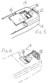
- Now referring to the drawing at Figure 8, this is a third embodiment and is the illustration of a most recent model of digital phone with in this case a battery being removed but as can be seen, there is an electrical take off card at 23 which is held in position by a slideable catch at 24 and in this case then electrical connections are run through a pathway as shown at 24 which then track around outer surfaces of the body until they meet the switch at 25 which has a visual window at 26 to indicate which one of two SIM cards has been chosen. There is an end switch member at 27 by which switching is achieved.
- In this case also, the
track 24 is adhered to the surface of the phone and by reason of its thinness and its material structure such that its substrate and cover is of polyester plastic materials, it is able to follow closely corners of the track with very small radius without fracture. The track is adhered to the surface of the phone casing to assist in long term stability and mechanical support. In this case, there is also provided an over cover protective coating also adhered across the track and to the casing at both sides of the track. - Figure 9 shows somewhat schematically the way in which the electrical track is located to extend between take off card at 28 and switch at 29.
- The
card 28 is held so that its conducting face will electrically connect with connectors such as 30 and then the track of the conducting layers will then follow as shown at 31 for instance until it reaches the switch means 29 where the track itself is folded into a circuitous shape so that respective Subscriber Identification Modules shown at 32 in the one case and 33 in the other will in each case have their oppositely directed electronic parts accessible for electrical connection to the track. - This is shown in a further instance in Figure 10 where the
track 34 passes from a take off at 35 to switch means at 36 with two Subscriber Identification Modules at 37 and 38 being adapted to be in electrical contact with their effective active connections. - A further example of this is in Figure 11 where again track 39 is shown to very closely follow an external shape of the phone body at 40 noting that the general crass hatching is schematic only. In this case again, battery at 41 then can be shown to leave quite clear at 42 any contact or need to squeeze the track 39.
- The track in this case again is of six thousandth of an inch total thickness and the tolerance or clearance between the respective mating members such as the battery. The housing will allow for an even larger thickness there between before there is interference with any effective action of the battery being relocated or being placed in position.
- There is a switch, in this case again at 43 with the Subscriber Identification Modules at 44 and 45. There is a, take off at 46.
- Referring now to Figures 12 and 13, the difference here is that this is an embodiment applying to a so called "flip phone".
- In this case, there is a cover shown at 47 which can be opened to reveal a keypad and also to provide a microphone position.
- In this case however, a switch means at 48 can be located on the outer surface of the
cover 47 and a flexible track at 49 can be allowed to stay clear of being adhered throughout to thecover 47 This allows for a hinging flexible action of the flexible track with a larger radius so that the track which is only six thousandth of an inch thickness can more readily allow for repeated hinging, without undo metal fatigue of the track materials. - Not shown is a connection of the track to an appropriate internal Subscriber Identification Module provided by the manufacturer.
- Figure 12 illustrates the fact that in this case, the Subscriber Identification Module is of a larger size such as the size of traditional credit card shown at 50 but here again it works in the same way as those applications previously described.
- We now refer to Figures 14 and 15. These Figures show specifically a typical track comprised of the dual laminate of polyester plastics materials and the inlaid copper track.
- There are at a take off location at 51 electrical contact points shown typically at 52 and 53 which are in turn, coated with an appropriate long lasting material such as gold or iridium and these are left open for electrical contact purposes.
- At the switch, contact with respective Subscriber Identification Modules is achieved by folding over the track and accordingly the track itself has two sets of electrical contactors shown at 54 in the one case and 55 in the other. There are breaks in the circuit shown at 56 so that an electrical contactor can variously connect connections say to the take off connectors at 58 in the one case or the connecters at 59 for connection to the contactors at 58 in the other.
- The way this works is shown more generally at Figure 16.
- Accordingly, referring to Figure 16, a track at 60 is folded over generally into an "S" shape so that upper most there are switch connectors at 61, 62 and 63, and such that two Subscriber Identification Modules at 64 and 65 will each fit in a slot shown at 66 so that both an upper and lower face of the two SIM cards will therefore present their electrically open contact surfaces.
- An electrical contact plate at 67 is held under the pressure of a
foam pad 68 within switchoperative plate 69 and such that respective electrical connections will bridge either between the contacts of 61 and 62 in the one case or 62 and 63 in the other and thereby bring into active connection the module either 64 in the one case or 65 in the other. - There is a housing at 71 and a cover at 72 to hold all of these pieces together. When assembled, the switch has a cross sectional view as shown in Figures 17 and 18 from where it will be seen that the
track 60 will be caused to bend tightly back on itself at 73 providing an uppermost surface by which the electrical connections at 67 can then effectively contact and bridge across the appropriate contact surfaces. - This then illustrates how the invention can be put into practice in various modes.
- From the description, it will be seen that there can be provided in a very effective way to substantially all of the mobile digital phones that are known to exist means to significantly improve these for access by the user in respect of providing alternate providers at the whim of the user. Such a modification can be economically prepared and provided, and can be installed very simply by appropriate people. It will not provide any interference to conventional enjoyment or the size or location of any digital mobile phone currently available.
- With conventionally engineered plastic covers there has been found to be ample gaps of sufficient size to slip electrical track there through and this enables connections to be made which do not rely in the slightest on any manufacturers approval because the inner electrical components are not prejudiced and warranties will therefor not be affected.
- At the same time this gives significant advantage to a consumer who can then simply and cheaply expand functions of a phone both by reason of easy alternative SIM card access and other logic connections.
Claims (9)
- A digital mobile phone of a type having a subscriber identification module wherein there are provided at least two subscriber identification modules and switch means accessible to the user and adapted for the user to select one or other of the modules.
- An external holder attachable to an existing mobile digital phone and adapted to take at least two subscriber identification module cards, switch means to provide access to any one of the subscriber identification module cards held in the external holder and means connecting such connected external subscriber identification module card electrically to a subscriber identification module take-off adaptor located within the existing internal subscriber identification module card holder of the digital mobile phone.
- A digital mobile phone of a type having a user removable subscriber identification module card within an internal holder characterised in that there is within the internal subscriber identification module card holder a take off card replacing any subscriber identification module therein and connecting to electrical connections for electrical connection of the subscriber identification module card to the phone and having a wire take-off for each subscriber identification module connection the wire take-off extending through to outside of the body of the mobile phone to an external subscriber identification module card holder, the external subscriber identification module card holder being adapted to hold at least two subscriber identification module cards with each having its electrical connections connected to the corresponding wire take offs connected to the wire take-off, and having a switch therewith to change effective active connection of the wire take offs from a first of any subscriber identification module cards in the external card holder to a second or other of any subscriber identification module cards in the external card holder.
- For a digital mobile phone of a type having a user removable subscriber identification module card within an internal subscriber identification module card holder, a take off card having a wire take-off for each subscriber identification module connection within the holder the wire take-off adapted to extend through to an outside of the body of the mobile phone to an external subscriber identification module card holder attached to the phone casing, the external subscriber identification module card holder being adapted to hold at least two subscriber identification module cards with each having its electrical connections connected to the corresponding wire take offs connected to the wire take-off, and having a switch therewith to change effective active connection of the wire take offs from a first of any subscriber identification module cards in the external card holder to a second or other of any subscriber identification module cards in the eternal card holder.
- A digital mobile phone of a type having a user removable subscriber identification module card within an internal holder, characterised in that there is within the internal subscriber identification module card holder a take-off card having electrical contacts replicating any subscriber identification module card that would otherwise be therein, and connecting to electrical connections for electrical connection in the phone and having a wire take-off for each subscriber identification module connection, the wire take-off in each case extending to an outside of the body of the mobile phone to an external subscriber identification module card holder, the external subscriber identification module card holder being adapted to hold at least two subscriber identification module cards each having its electrical connections connected to the corresponding wire take-offs connected to the take-off card, and having a switch therewith adapted to change effective active connection from one of the subscriber identification module cards in the external card holder to a second of the subscriber identification module cards in the external card holder.
- Any one of the preceding claims 2 through 5 further characterised in that the wire take offs are together an integrated flexible circuit board where there is a substrate, a laid conducting track for each circuit on the substrate and an overlay coating.
- Any one of the preceding claims 2 through 6 further characterised in that the wire take offs are together an integrated flexible circuit board where there is a substrate comprised of polyester plastics material, a laid conducting track for each circuit on the substrate and an overlay coating of polyester plastics material.
- A digital phone substantially as described in the specification with reference to and as illustrated by any one of the Figures of the accompanying drawings.
- A take off card having a wire take-off for each subscriber identification module connection within the holder the wire take-off adapted to extend through to an outside of the body of the mobile phone to an external subscriber identification module card holder attached to a casing of the phone being substantially as described in the specification with reference to and as illustrated by Figures of the accompanying drawings.
Priority Applications (2)
| Application Number | Priority Date | Filing Date | Title |
|---|---|---|---|
| DE29623956U DE29623956U1 (en) | 1996-01-15 | 1996-12-16 | External switch for subscriber identification modules for mobile phones |
| EP02255375A EP1263147A3 (en) | 1996-01-15 | 1996-12-16 | Improvements relating to mobile phones |
Applications Claiming Priority (3)
| Application Number | Priority Date | Filing Date | Title |
|---|---|---|---|
| AUPN755196 | 1996-01-15 | ||
| AUPN7551A AUPN755196A0 (en) | 1996-01-15 | 1996-01-15 | Improvements relating to mobile phones |
| AUPN7551/96 | 1996-01-15 |
Related Child Applications (1)
| Application Number | Title | Priority Date | Filing Date |
|---|---|---|---|
| EP02255375A Division EP1263147A3 (en) | 1996-01-15 | 1996-12-16 | Improvements relating to mobile phones |
Publications (2)
| Publication Number | Publication Date |
|---|---|
| EP0785634A2 true EP0785634A2 (en) | 1997-07-23 |
| EP0785634A3 EP0785634A3 (en) | 1999-11-24 |
Family
ID=3791869
Family Applications (2)
| Application Number | Title | Priority Date | Filing Date |
|---|---|---|---|
| EP96309177A Withdrawn EP0785634A3 (en) | 1996-01-15 | 1996-12-16 | Mobile phone with SIM card |
| EP02255375A Withdrawn EP1263147A3 (en) | 1996-01-15 | 1996-12-16 | Improvements relating to mobile phones |
Family Applications After (1)
| Application Number | Title | Priority Date | Filing Date |
|---|---|---|---|
| EP02255375A Withdrawn EP1263147A3 (en) | 1996-01-15 | 1996-12-16 | Improvements relating to mobile phones |
Country Status (8)
| Country | Link |
|---|---|
| US (2) | US6292561B1 (en) |
| EP (2) | EP0785634A3 (en) |
| CN (1) | CN1134125C (en) |
| AU (1) | AUPN755196A0 (en) |
| DE (1) | DE29623956U1 (en) |
| ES (1) | ES2147718T1 (en) |
| WO (1) | WO1997026719A1 (en) |
| ZA (1) | ZA9797B (en) |
Cited By (12)
| Publication number | Priority date | Publication date | Assignee | Title |
|---|---|---|---|---|
| GB2333926A (en) * | 1998-01-16 | 1999-08-04 | Motorola Inc | Communication device with removable user interface card |
| US6044263A (en) * | 1996-12-18 | 2000-03-28 | Ericsson Inc. | Method for providing a location independent dialing procedure within a mobile telecommunications network |
| AU722256B3 (en) * | 2000-05-17 | 2000-07-27 | Ping Chang Lu | Mobile phone battery set with replaceable SIM card mounting board |
| EP1054339A1 (en) * | 1999-05-21 | 2000-11-22 | Alcatel | Apparatus with a latch for an object insertable in its housing, a housing comprising a latch and a process for mounting a latch in a housing |
| EP1068753A1 (en) * | 1998-06-15 | 2001-01-17 | Newcom Holdings Pty. Ltd. | Communication method and apparatus improvements |
| EP1077578A1 (en) * | 1999-07-30 | 2001-02-21 | Simone Baldan | Mobile phone adapter for housing and switching two or more SIM cards |
| WO2001080437A1 (en) * | 2000-04-19 | 2001-10-25 | Polti S.P.A. | Mobile telephone accessory |
| WO2002051021A1 (en) * | 2000-12-20 | 2002-06-27 | Koninklijke Philips Electronics N.V. | Processing device for the contactless communication with a data carrier which is detachably connected to the processing device |
| EP1231800A1 (en) * | 2001-02-08 | 2002-08-14 | Christ Verwaltungsgesellschaft mbH | Mobile telephone with two SIM-Cards or two Identity-Microchips |
| WO2002065654A1 (en) * | 2001-02-13 | 2002-08-22 | Polti S.P.A. | Mobile telephone case |
| EP1058872B2 (en) † | 1998-02-25 | 2011-04-06 | TELEFONAKTIEBOLAGET LM ERICSSON (publ) | Method, arrangement and apparatus for authentication through a communications network |
| US7945243B2 (en) | 2003-10-07 | 2011-05-17 | Samsung Electronics Co., Ltd | Mobile communication terminal for protecting private contents and method for controlling the same |
Families Citing this family (31)
| Publication number | Priority date | Publication date | Assignee | Title |
|---|---|---|---|---|
| IT1305659B1 (en) * | 1998-02-16 | 2001-05-15 | Giorgio Liverotti | GSM MOBILE TERMINAL PERFECTED |
| ES2251072T3 (en) | 1998-03-06 | 2006-04-16 | Giovanni Ferrara | ELECTRONIC DEVICE FOR FUNCTIONAL FOLDING WITH MULTIPLE CELL PHONE CARDS. |
| GB2336507B (en) * | 1998-04-16 | 2003-02-12 | Motorola Ltd | Data carrier system |
| FI107973B (en) | 1999-03-11 | 2001-10-31 | Nokia Mobile Phones Ltd | Method and means for using option cards in a mobile station |
| FR2794264B1 (en) * | 1999-05-27 | 2001-11-02 | Gemplus Card Int | ADAPTER FOR PORTABLE ELECTRONIC DEVICE WITH INTEGRATED CIRCUIT, OF THE CHIP CARD TYPE, OF A REDUCED FORMAT IN RELATION TO THE STANDARD FORMAT OF A MINI-CARD |
| AU2000247404A1 (en) * | 2000-05-18 | 2001-12-03 | Junqin Huang | Multi-card mobile phone |
| CN1369179A (en) * | 2000-05-18 | 2002-09-11 | 黄俊钦 | Multi-card mobile phone and multi-card control method |
| CN1196361C (en) * | 2001-05-04 | 2005-04-06 | Lg电子株式会社 | Device and method of verifying subscriber identifying module card |
| US6766952B2 (en) * | 2001-11-06 | 2004-07-27 | Quadnovation, Inc. | SIM card carrier |
| US7403802B2 (en) * | 2002-04-11 | 2008-07-22 | Lg Electronics Inc. | Battery and battery locking unit of mobile terminal |
| TW592420U (en) * | 2002-04-19 | 2004-06-11 | Quanta Comp Inc | Mobile phone |
| US7090127B2 (en) * | 2002-07-08 | 2006-08-15 | The Boeing Company | Connector identification module for mobile platform |
| US20040230489A1 (en) * | 2002-07-26 | 2004-11-18 | Scott Goldthwaite | System and method for mobile payment and fulfillment of digital goods |
| US20040019564A1 (en) * | 2002-07-26 | 2004-01-29 | Scott Goldthwaite | System and method for payment transaction authentication |
| US7336973B2 (en) * | 2002-10-30 | 2008-02-26 | Way Systems, Inc | Mobile communication device equipped with a magnetic stripe reader |
| US20040127256A1 (en) * | 2002-07-30 | 2004-07-01 | Scott Goldthwaite | Mobile device equipped with a contactless smart card reader/writer |
| US7278584B1 (en) * | 2002-11-07 | 2007-10-09 | American Express Travel Related Services Company, Inc. | Portable electronic music devices with convenient or foldable transaction cards |
| US7540426B1 (en) | 2002-11-07 | 2009-06-02 | American Express Travel Related Services Company, Inc. | Foldable transaction cards and methods of making the same |
| CN1860730B (en) * | 2003-03-19 | 2010-06-16 | 路径系统公司 | System and method for mobile transactions using the bearer independent protocol |
| WO2004088641A2 (en) * | 2003-03-26 | 2004-10-14 | Way Systems, Inc. | System and method for securely storing, generating, transferring and printing electronic prepaid vouchers |
| JP4219756B2 (en) * | 2003-07-23 | 2009-02-04 | 京セラ株式会社 | Mobile terminal device |
| GB2405249B (en) * | 2003-08-22 | 2007-03-07 | Ipwireless Inc | Holder for module and method therefor |
| US7721956B2 (en) | 2003-12-10 | 2010-05-25 | American Express Travel Related Services Company, Inc. | Foldable transaction card systems |
| US20110071949A1 (en) * | 2004-09-20 | 2011-03-24 | Andrew Petrov | Secure pin entry device for mobile phones |
| US20060064391A1 (en) * | 2004-09-20 | 2006-03-23 | Andrew Petrov | System and method for a secure transaction module |
| US20060222170A1 (en) * | 2005-03-31 | 2006-10-05 | Payzant Nick L | External system to provide an electronic device with access to memory external to the electronic device |
| EP1788827A1 (en) * | 2005-11-18 | 2007-05-23 | Delphi Technologies, Inc. | Communication system with SIM-card reader |
| TWI351209B (en) * | 2007-07-25 | 2011-10-21 | High Tech Comp Corp | Electronic apparatus and flexible printed circuit board thereof |
| SK288757B6 (en) * | 2008-09-19 | 2020-05-04 | Smk Kk | System and method for contactless payment authorization |
| EP2462567A2 (en) | 2009-05-03 | 2012-06-13 | Logomotion, s.r.o. | A payment terminal using a mobile communication device, such as a mobile phone; a method of direct debit payment transaction |
| WO2011011901A1 (en) * | 2009-07-31 | 2011-02-03 | Gemalto Sa | Contactless adaptor device |
Citations (4)
| Publication number | Priority date | Publication date | Assignee | Title |
|---|---|---|---|---|
| US4677653A (en) | 1986-06-16 | 1987-06-30 | B/W Investments | Cellular mobile phone with a plurality of accessing telephone numbers for allowing access to the mobile phone by any one of the telephone numbers |
| GB2269152A (en) | 1992-07-30 | 1994-02-02 | Metal Box Plc | Container end wall |
| WO1995032590A2 (en) | 1994-05-13 | 1995-11-30 | Telecom Finland Oy | Method for calling by a terminal, like a card controlled mobile station, of a mobile communication system |
| EP0690645A1 (en) | 1994-06-30 | 1996-01-03 | Casio Computer Company Limited | Radio communication apparatus having a plurality of identification codes |
Family Cites Families (15)
| Publication number | Priority date | Publication date | Assignee | Title |
|---|---|---|---|---|
| DE3721889A1 (en) | 1987-07-02 | 1989-01-12 | Standard Elektrik Lorenz Ag | COMPUTER CONTROLLED SUBSCRIBER DEVICE FOR OPERATION IN TELECOMMUNICATION NETWORKS, IN PARTICULAR MOBILE RADIO NETWORKS, WITH DIFFERENT SYSTEM TECHNOLOGY |
| US5184282A (en) * | 1989-02-27 | 1993-02-02 | Mips Co., Ltd. | IC card adapter |
| CA2064646A1 (en) | 1991-04-02 | 1992-10-03 | Kipling W. Fyfe | Automatic number assignment module selection for mobile telephone |
| SE467559B (en) * | 1991-04-12 | 1992-08-03 | Comvik Gsm Ab | PHONE SYSTEM PROCEDURES |
| FI90298C (en) * | 1992-02-18 | 1994-01-10 | Nokia Mobile Phones Ltd | The card reader device |
| GB2269512B (en) * | 1992-08-03 | 1996-08-14 | Nokia Mobile Phones Uk | Radio arrangement |
| SE470041B (en) * | 1992-10-01 | 1993-10-25 | Nordictel Ab | Digital mobile telephone system in which each subscription is assigned a subscriber number and multiple subscriber cards (SIM) |
| DE4302820C2 (en) * | 1993-01-28 | 1997-03-20 | Mannesmann Ag | Installation radio telephone device or mobile handheld device |
| DE4307122A1 (en) | 1993-03-06 | 1994-09-08 | Sel Alcatel Ag | Smart card |
| JPH07123262B2 (en) * | 1993-03-19 | 1995-12-25 | 日本電気株式会社 | Mobile phone |
| FR2711866B1 (en) * | 1993-10-26 | 1996-05-24 | Alcatel Mobile Comm France | Installation of digital radio-telephone with mobile terminals. |
| JP3213872B2 (en) * | 1994-12-28 | 2001-10-02 | モレックス インコーポレーテッド | Telephone information card drive for mobile phone |
| US5815426A (en) | 1996-08-13 | 1998-09-29 | Nexcom Technology, Inc. | Adapter for interfacing an insertable/removable digital memory apparatus to a host data part |
| US5884168A (en) | 1996-08-30 | 1999-03-16 | Ericsson, Inc. | Multiple cellular systems with limited sim card information |
| US5894597A (en) | 1996-09-24 | 1999-04-13 | Motorola, Inc. | Communication device for different sized cards |
-
1996
- 1996-01-15 AU AUPN7551A patent/AUPN755196A0/en not_active Abandoned
- 1996-12-13 WO PCT/AU1996/000802 patent/WO1997026719A1/en active Application Filing
- 1996-12-13 CN CNB961801824A patent/CN1134125C/en not_active Expired - Fee Related
- 1996-12-16 DE DE29623956U patent/DE29623956U1/en not_active Expired - Lifetime
- 1996-12-16 EP EP96309177A patent/EP0785634A3/en not_active Withdrawn
- 1996-12-16 ES ES96309177T patent/ES2147718T1/en active Pending
- 1996-12-16 EP EP02255375A patent/EP1263147A3/en not_active Withdrawn
-
1997
- 1997-01-07 ZA ZA9797A patent/ZA9797B/en unknown
- 1997-01-14 US US08/782,244 patent/US6292561B1/en not_active Expired - Fee Related
-
2000
- 2000-08-15 US US09/638,394 patent/US20020198018A1/en not_active Abandoned
Patent Citations (4)
| Publication number | Priority date | Publication date | Assignee | Title |
|---|---|---|---|---|
| US4677653A (en) | 1986-06-16 | 1987-06-30 | B/W Investments | Cellular mobile phone with a plurality of accessing telephone numbers for allowing access to the mobile phone by any one of the telephone numbers |
| GB2269152A (en) | 1992-07-30 | 1994-02-02 | Metal Box Plc | Container end wall |
| WO1995032590A2 (en) | 1994-05-13 | 1995-11-30 | Telecom Finland Oy | Method for calling by a terminal, like a card controlled mobile station, of a mobile communication system |
| EP0690645A1 (en) | 1994-06-30 | 1996-01-03 | Casio Computer Company Limited | Radio communication apparatus having a plurality of identification codes |
Cited By (18)
| Publication number | Priority date | Publication date | Assignee | Title |
|---|---|---|---|---|
| US6044263A (en) * | 1996-12-18 | 2000-03-28 | Ericsson Inc. | Method for providing a location independent dialing procedure within a mobile telecommunications network |
| US6118986A (en) * | 1998-01-16 | 2000-09-12 | Motorola, Inc. | Device for use with a user interface card |
| GB2333926A (en) * | 1998-01-16 | 1999-08-04 | Motorola Inc | Communication device with removable user interface card |
| GB2333926B (en) * | 1998-01-16 | 2002-04-10 | Motorola Inc | Device for use with a user interface card |
| EP1058872B2 (en) † | 1998-02-25 | 2011-04-06 | TELEFONAKTIEBOLAGET LM ERICSSON (publ) | Method, arrangement and apparatus for authentication through a communications network |
| EP1068753A4 (en) * | 1998-06-15 | 2004-05-12 | Aussie L L C Pty Ltd | Communication method and apparatus improvements |
| EP1068753A1 (en) * | 1998-06-15 | 2001-01-17 | Newcom Holdings Pty. Ltd. | Communication method and apparatus improvements |
| EP1054339A1 (en) * | 1999-05-21 | 2000-11-22 | Alcatel | Apparatus with a latch for an object insertable in its housing, a housing comprising a latch and a process for mounting a latch in a housing |
| FR2793956A1 (en) * | 1999-05-21 | 2000-11-24 | Cit Alcatel | APPARATUS PROVIDED IN A LOCK HOUSING FOR AN INSERT, HOUSING HAVING A LOCK AND METHOD OF MOUNTING A LOCK IN A HOUSING |
| EP1077578A1 (en) * | 1999-07-30 | 2001-02-21 | Simone Baldan | Mobile phone adapter for housing and switching two or more SIM cards |
| WO2001080437A1 (en) * | 2000-04-19 | 2001-10-25 | Polti S.P.A. | Mobile telephone accessory |
| AU722256B3 (en) * | 2000-05-17 | 2000-07-27 | Ping Chang Lu | Mobile phone battery set with replaceable SIM card mounting board |
| WO2002051021A1 (en) * | 2000-12-20 | 2002-06-27 | Koninklijke Philips Electronics N.V. | Processing device for the contactless communication with a data carrier which is detachably connected to the processing device |
| US8160644B2 (en) | 2000-12-20 | 2012-04-17 | Nxp B.V. | Processing device for the contactless communication with a data carrier which is detachably connected to the processing device |
| US8538481B2 (en) | 2000-12-20 | 2013-09-17 | Nxp B.V. | Processing device for the contactless communication with a data carrier which is detachably connected to the processing device |
| EP1231800A1 (en) * | 2001-02-08 | 2002-08-14 | Christ Verwaltungsgesellschaft mbH | Mobile telephone with two SIM-Cards or two Identity-Microchips |
| WO2002065654A1 (en) * | 2001-02-13 | 2002-08-22 | Polti S.P.A. | Mobile telephone case |
| US7945243B2 (en) | 2003-10-07 | 2011-05-17 | Samsung Electronics Co., Ltd | Mobile communication terminal for protecting private contents and method for controlling the same |
Also Published As
| Publication number | Publication date |
|---|---|
| WO1997026719A1 (en) | 1997-07-24 |
| CN1214162A (en) | 1999-04-14 |
| ES2147718T1 (en) | 2000-10-01 |
| EP0785634A3 (en) | 1999-11-24 |
| EP1263147A2 (en) | 2002-12-04 |
| AUPN755196A0 (en) | 1996-02-08 |
| EP1263147A3 (en) | 2003-01-02 |
| US20020198018A1 (en) | 2002-12-26 |
| ZA9797B (en) | 1997-07-17 |
| DE29623956U1 (en) | 2000-11-16 |
| CN1134125C (en) | 2004-01-07 |
| US6292561B1 (en) | 2001-09-18 |
Similar Documents
| Publication | Publication Date | Title |
|---|---|---|
| US6292561B1 (en) | Digital mobile phone with a plurality of switchable subscriber identification modules (SIMS) | |
| US6973186B2 (en) | Slide type mobile phone using slide module | |
| US6151511A (en) | Adapter for integrated circuit cards for cellular telephones | |
| US7300314B2 (en) | Socket for trans-flash memory card | |
| US20050139683A1 (en) | Communication terminal equipped with a replaceable cover and method of changing themes of communication terminal using the same | |
| EP1881681B1 (en) | Mobile phone | |
| JP2002536916A (en) | Communication terminal | |
| CN102573364B (en) | Esd protection in a very small form factor consumer electronic product | |
| JPH09247252A (en) | Radio telephone set | |
| JP3423003B2 (en) | Microphone connection device for flip type mobile phone | |
| AU3720797A (en) | Radiotelephone having a combination fastener and electrical connector | |
| EP1128489A1 (en) | Connector for printed circuit and equipment which includes it | |
| KR100576008B1 (en) | Main board for portable terminal | |
| JP3439868B2 (en) | Mobile phone | |
| AU729999B3 (en) | Improvements relating to mobile phones | |
| AU709524B3 (en) | Improvements relating to mobile phones | |
| AU2810899A (en) | Improvements relating to mobile phones | |
| AU2081700A (en) | Improvements relating to an attachment for mobile phones | |
| KR100608832B1 (en) | Multi socket for mobile communication terminal | |
| US7773958B2 (en) | Key pad assembly and mobile communication terminal having the same | |
| RU2406223C2 (en) | Mobile telephone | |
| JP2002185587A (en) | Digital portable telephone | |
| KR100406243B1 (en) | Card with incorporated ic device | |
| ITRM20000393A1 (en) | IMPROVEMENTS REGARDING MOBILE PHONES. | |
| CN201319422Y (en) | Card connector |
Legal Events
| Date | Code | Title | Description |
|---|---|---|---|
| PUAI | Public reference made under article 153(3) epc to a published international application that has entered the european phase |
Free format text: ORIGINAL CODE: 0009012 |
|
| AK | Designated contracting states |
Kind code of ref document: A2 Designated state(s): AT BE CH DE DK ES FI FR GB GR IE IT LI LU MC NL PT SE |
|
| PUAL | Search report despatched |
Free format text: ORIGINAL CODE: 0009013 |
|
| AK | Designated contracting states |
Kind code of ref document: A3 Designated state(s): AT BE CH DE DK ES FI FR GB GR IE IT LI LU MC NL PT SE |
|
| 17P | Request for examination filed |
Effective date: 19991230 |
|
| 17Q | First examination report despatched |
Effective date: 20000222 |
|
| TPAD | Observations filed by third parties |
Free format text: ORIGINAL CODE: EPIDOS TIPA |
|
| EL | Fr: translation of claims filed | ||
| REG | Reference to a national code |
Ref country code: ES Ref legal event code: BA2A Ref document number: 2147718 Country of ref document: ES Kind code of ref document: T1 |
|
| GRAH | Despatch of communication of intention to grant a patent |
Free format text: ORIGINAL CODE: EPIDOS IGRA |
|
| STAA | Information on the status of an ep patent application or granted ep patent |
Free format text: STATUS: THE APPLICATION IS DEEMED TO BE WITHDRAWN |
|
| 18D | Application deemed to be withdrawn |
Effective date: 20030520 |