EP0785531A2 - Verfahren und Gerät zur Steifheitsüberprüfung mit einem vom Einfluss der Bildresolution befreiten Ergebnis - Google Patents
Verfahren und Gerät zur Steifheitsüberprüfung mit einem vom Einfluss der Bildresolution befreiten Ergebnis Download PDFInfo
- Publication number
- EP0785531A2 EP0785531A2 EP97100461A EP97100461A EP0785531A2 EP 0785531 A2 EP0785531 A2 EP 0785531A2 EP 97100461 A EP97100461 A EP 97100461A EP 97100461 A EP97100461 A EP 97100461A EP 0785531 A2 EP0785531 A2 EP 0785531A2
- Authority
- EP
- European Patent Office
- Prior art keywords
- det
- calculating
- rigidity
- target object
- covariance matrix
- Prior art date
- Legal status (The legal status is an assumption and is not a legal conclusion. Google has not performed a legal analysis and makes no representation as to the accuracy of the status listed.)
- Withdrawn
Links
Images
Classifications
-
- G—PHYSICS
- G06—COMPUTING OR CALCULATING; COUNTING
- G06T—IMAGE DATA PROCESSING OR GENERATION, IN GENERAL
- G06T7/00—Image analysis
- G06T7/30—Determination of transform parameters for the alignment of images, i.e. image registration
- G06T7/33—Determination of transform parameters for the alignment of images, i.e. image registration using feature-based methods
Definitions
- the present invention relates to a rigidity checking method and apparatus for effectively checking the rigidity of an object perceived by a automated robot or vehicle, or of an object indruding into the sensing field of monitor camera.
- the distance between two arbitrary points on a rigid body remains unchanged even when the rigid body takes a force or moves. This property of the rigid body permits a decision to be made from an image sequence including a target body as to whether the target body is a rigid body or not.
- a rigidity checking technique is described in detail by S. Ullman and R. Basri, Object Recognition by Liner Combination of the Model, IEEE Trans. PAMI (Pattern Analysis and Machine Intelligence).
- the optimum values are conventionally found for the coefficients of the constraint equations by means of least square error estimate by using a sufficient number of feature points. Then, the residue of each constraint equation is calculated as a satisfaction degree. It is determined that the smaller the residues or the satisfaction degrees are, the more rigidity the target object has.
- the values of the constraint equations changes with a change in the resolutions of the three pictures. Since the resolutions of the pictures which have essentially nothing to do with the rigidity of the target object have effects on a judgement of the rigidity of the target object, the conventional rigid checking technique is not suitable for a general purpose tool.
- the conventional rigid checking technique requires calculations of the coefficients of the constraint equations which have no direct relationship with the rigidity of the target object, and accordingly is not effective.
- a composite feature vector is first generated by combining three pairs of coordinates obtained for a feature point of a target object from three pictures of the target object; a covariance matrix of the compound feature vector is calculated by finding a product of a variance matrix comprising a variance of each element of the compound feature vector and the transposed matrix of the variance matrix; the rigidity of the target object is calculated by using the element of the covariance matrix; and the rigidity is compared with a predetermined threshold to determine whether the target object is a rigid body.
- a rigidity checking is directly achieved from the joint distribution of feature points in the three pictures without recovering the coefficients of a set of constraint equations for estimating the residue of each constraint equation as done in the prior art.
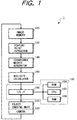
- Fig. 1 is a block diagram showing a first illustrative embodiment of an object chasing system incorporating a rigidity checking apparatus realized with dedicated hardware according to the present invention.
- the object chasing system 1 comprises a self-propelled object chasing unit 170, a camera 100 mounted on the object chasing unit 170, an image memory 120 for storing images supplied from the camera 100, a feature point extractor 130 for extracting a feature point of a target object from three images in the image memory 120 and complete a compound feature vector, a covariance matrix generator 140 for calculating a covariance matrix from the compound feature vector, a rigidity calculator 150 for calculating the rigidity of the target object by using a equation comprising a combination of elements of the covariance matrix, and a controller 160 for controlling the object chasing unit 170 in response to the result of the rigidity checking by a comparison of the calculated rigidity with a predetermined threshold.
- the comparison may be executed by either the rigidity calculator 150 or the controller 160.
- the controller 160 comprises a central processing unit (CPU) 162, a read only memory (ROM) 164 for storing a program and data, a random access memory (RAM) 166, and an input and output interface (I/O IF) 168 as well known in the art.
- CPU central processing unit
- ROM read only memory
- RAM random access memory
- I/O IF input and output interface
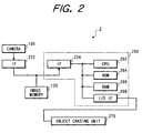
- FIG. 2 is a block diagram showing a second illustrative embodiment of an object chasing system incorporating a rigidity checking apparatus realized with a microcomputer according to the present invention.
- the object chasing system 2 comprising a camera 100, an image memory 120, an input interface (IF) 222 through which an image data is supplied from the camera 100 to the memory 120, a microcomputer 260 for performing a rigidity checking, and an object chasing unit 270 which includes a controller (not shown) for controlling the unit 270 itself.
- IF input interface
- the microcomputer 260 comprises a CPU 262, a ROM 262 for storing a program and data for rigidity checking, a RAM 266, an out put interface 224 through which the image data is read from the memory 120, and an input and output interface (I/O IF) 268 through which the CPU 262 communicates with the controller (not shown) of the unit 270.
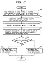
- Fig. 3 is a flow chart showing a flow of a rigidity checking operation executed by the elements 130, 140, 150 and 162 in case of the apparatus 1 of Fig. 1 and by CPU 266 under the control of the program stored in ROM 266 in case of the apparatus 2 of Fig. 2. Therefore, the rigidity checking operation will be described referring to Fig. 1 and 3 in the following, where a description corresponding to any of the steps of Fig. 3 is indicated by a step number in parentheses.
- An two-dimension (2-D) image of a target object is supplied to the memory 120 from the camera 100 mounted on the object chasing unit 170 (or 270).
- the feature point extractor 130 selects three frames in which the target object has moved sufficiently in distance, N+1 feature points on the target object are selected from a first one of the three selected frames, corresponding N+1 feature points are found from each of the two remaining frames, and N 2-D feature point vectors from one of the N+1 feature points to the N other feature points are found for each of the three frames (step 300) and expressed as:
- the rigidity calculator 150 compares the calculated rigidity R with a predetermined threshold to see if the rigidity R is equal to or larger than the threshold. If so, the calculator 150 sends a signal indicative of a rigid body to the CPU 162, and otherwise sends the opposite signal indicative of a unrigid body to the CPU 162.
- the rigidity calculator 150 sends the calculated rigidity R as it is to the CPU 162, which in turn compares the calculated rigidity R with a predetermined threshold to see if the rigidity R is equal to or larger than the threshold (step 340). If so, the CPU 162 determines that the target object is a rigid body (step 350), and otherwise determines that the target body is an unrigid body (step 360).
- Equations (1) and (2) concern the feature point [Xn 1 , Yn 1 ] , [Xn 2 , Yn 2 ] and [Xn 3 , Yn 3 ] will satisfy the above mentioned equations (1) through (6).
- Equations (1) and (2) concern the feature point [Xn 1 , Yn 1 ]
- equations (3) and (4) concern the feature point [Xn 2 , Yn 2 ]
- equations (3) and (4) concern the feature point [Xn 3 , Yn 3 ].
- det[C1] is a quantity indicating the volume defined by four dimensional extent of the vector field of the vector [X 1 , Y 1 , X 2 , X 3 ] and that det[C1] is suitable for a quantity for estimating the dimensional degeneracy (degeneracy from four-dimensional extent to three-dimensional extent).
- the rigidity of the target is defined on the basis of the constraint equation (1) by the following expression: 1 - ⁇ 1 ⁇ 2 ⁇ 3 ⁇ 4 /(( ⁇ 1 + ⁇ 2 + ⁇ 3 + ⁇ 4 )/4) 4 ⁇ , where ⁇ 1 , ⁇ 2 , ⁇ 3 and ⁇ 4 are eigenvalues of the covariance matrix for (X 1 ', Y 1 ', X 2 ', X 3 ') in equation (11).
- the estimated value of the rigidity can be obtained by taking a mean of the estimates based on the constraint equations.
- Equation (2) that takes the mean. Therefore, in calculating the rigidity, the degree of the feature points satisfying the constraint equation which characterizes the property of a rigid body is calculated by combining the components of the covariance matrix.
- a rigidity checking system judges the rigidity of a target directly from the joint distribution of the feature points instead of assuming the coefficients of the constraint equation and estimating the rigidity by using the residues of the constraint equation as in the prior art.
- the rigidity of the target object may be calculated by using the following equation: Q 1 1 + Q 1 2 + Q 2 1 + Q 2 2 + Q 3 1 + Q 3 2 ,
- the rigidity of the target object may be calculated by using the following equation into which the equation (14) has been modified: Q 1 + Q 2 + Q 3 ,
- the rigidity of the target object may be calculated by using the following equation into which the equation (15) has been modified: Q 0 ⁇ ⁇ (1-k) ⁇ det ⁇ C2 ⁇ (C 33 C 55 + C 44 C 66 ) + det ⁇ C5 ⁇ (C 11 C 55 + C 22 C 66 ) + det ⁇ C8 ⁇ (C 11 C 33 + C 22 C 44 ) ⁇ - (det ⁇ C1 ⁇ + det ⁇ C3 ⁇ + det ⁇ C4 ⁇ + det ⁇ C6 ⁇ + det ⁇ C7 ⁇ + det ⁇ C9 ⁇ ) ⁇ /(1-k) ⁇ det ⁇ C2 ⁇ (C 33 C 55 + C 44 C 66 ) + det ⁇ C5 ⁇ (C 11 C 55 + C 22 C 66 ) + det ⁇ C8 ⁇ (C 11 C 33 + C 22 C 44 ) ⁇ If equation (17) or (18) is used, the rigidity of the target object can be properly calculated by adjusting the value of k.
Landscapes
- Engineering & Computer Science (AREA)
- Computer Vision & Pattern Recognition (AREA)
- Physics & Mathematics (AREA)
- General Physics & Mathematics (AREA)
- Theoretical Computer Science (AREA)
- Image Analysis (AREA)
- Length Measuring Devices By Optical Means (AREA)
- Investigating Materials By The Use Of Optical Means Adapted For Particular Applications (AREA)
- Image Processing (AREA)
Applications Claiming Priority (3)
| Application Number | Priority Date | Filing Date | Title |
|---|---|---|---|
| JP8023010A JPH09198496A (ja) | 1996-01-17 | 1996-01-17 | 剛体/非剛体判別装置 |
| JP2301096 | 1996-01-17 | ||
| JP23010/96 | 1996-01-17 |
Publications (2)
| Publication Number | Publication Date |
|---|---|
| EP0785531A2 true EP0785531A2 (de) | 1997-07-23 |
| EP0785531A3 EP0785531A3 (de) | 2002-07-03 |
Family
ID=12098531
Family Applications (1)
| Application Number | Title | Priority Date | Filing Date |
|---|---|---|---|
| EP97100461A Withdrawn EP0785531A3 (de) | 1996-01-17 | 1997-01-14 | Verfahren und Gerät zur Steifheitsüberprüfung mit einem vom Einfluss der Bildresolution befreiten Ergebnis |
Country Status (3)
| Country | Link |
|---|---|
| US (1) | US5870507A (de) |
| EP (1) | EP0785531A3 (de) |
| JP (1) | JPH09198496A (de) |
Families Citing this family (1)
| Publication number | Priority date | Publication date | Assignee | Title |
|---|---|---|---|---|
| EP1754621B1 (de) * | 2005-08-18 | 2009-10-14 | Honda Research Institute Europe GmbH | Fahrerassistenzsystem |
Family Cites Families (1)
| Publication number | Priority date | Publication date | Assignee | Title |
|---|---|---|---|---|
| US4783744A (en) * | 1986-12-08 | 1988-11-08 | General Dynamics, Pomona Division | Self-adaptive IRU correction loop design interfacing with the target state estimator for multi-mode terminal handoff |
-
1996
- 1996-01-17 JP JP8023010A patent/JPH09198496A/ja not_active Withdrawn
-
1997
- 1997-01-09 US US08/780,908 patent/US5870507A/en not_active Expired - Fee Related
- 1997-01-14 EP EP97100461A patent/EP0785531A3/de not_active Withdrawn
Non-Patent Citations (1)
| Title |
|---|
| "Measurement and Automatic Control Society of Japan.", article "Matrix Theory for System Control", pages: 136 - 137 |
Also Published As
| Publication number | Publication date |
|---|---|
| EP0785531A3 (de) | 2002-07-03 |
| JPH09198496A (ja) | 1997-07-31 |
| US5870507A (en) | 1999-02-09 |
Similar Documents
| Publication | Publication Date | Title |
|---|---|---|
| EP1677250B1 (de) | Bildkollationierungssystem und bildkollationierungsverfahren | |
| US6185337B1 (en) | System and method for image recognition | |
| KR102011628B1 (ko) | 검사 장치 및 검사 방법 | |
| CN110378181B (zh) | 图像解析装置、图像解析方法及记录介质 | |
| EP1811456B1 (de) | Gesichtsmerkmal-punktdetektor und merkmalpunktdetektor | |
| Lanitis et al. | Automatic face identification system using flexible appearance models | |
| Craw et al. | Finding face features | |
| JP4546956B2 (ja) | 奥行き検出を用いた対象の向きの推定 | |
| US6526156B1 (en) | Apparatus and method for identifying and tracking objects with view-based representations | |
| EP0555380B1 (de) | Gesichterkennungssystem | |
| Micheli et al. | The accuracy of the computation of optical flow and of the recovery of motion parameters | |
| EP2637141A2 (de) | Verfahren und Vorrichtung zur Haltungserkennung | |
| US6345109B1 (en) | Face recognition-matching system effective to images obtained in different imaging conditions | |
| US7224823B2 (en) | Parameter estimation apparatus and data matching apparatus | |
| US6820137B2 (en) | Computer-readable recording medium storing resolution converting program, resolution converting device and resolution converting method | |
| US7697732B2 (en) | Data processing apparatus, data processing method and recording medium | |
| US20030059124A1 (en) | Real-time facial recognition and verification system | |
| US6628811B1 (en) | Method and apparatus for recognizing image pattern, method and apparatus for judging identity of image patterns, recording medium for recording the pattern recognizing method and recording medium for recording the pattern identity judging method | |
| CN110378182B (zh) | 图像解析装置、图像解析方法及记录介质 | |
| DE102009001921A1 (de) | Vorrichtung und Verfahren zur Feststellung einer Sichtlinie | |
| US5101337A (en) | Plant diagnostic apparatus | |
| JP2021503139A (ja) | 画像処理装置、画像処理方法および画像処理プログラム | |
| Viéville et al. | Using singular displacements for uncalibrated monocular visual systems | |
| Kruger et al. | Affine real-time face tracking using a wavelet network | |
| EP0785531A2 (de) | Verfahren und Gerät zur Steifheitsüberprüfung mit einem vom Einfluss der Bildresolution befreiten Ergebnis |
Legal Events
| Date | Code | Title | Description |
|---|---|---|---|
| PUAI | Public reference made under article 153(3) epc to a published international application that has entered the european phase |
Free format text: ORIGINAL CODE: 0009012 |
|
| 17P | Request for examination filed |
Effective date: 19970114 |
|
| AK | Designated contracting states |
Kind code of ref document: A2 Designated state(s): DE FR GB |
|
| PUAL | Search report despatched |
Free format text: ORIGINAL CODE: 0009013 |
|
| RIC1 | Information provided on ipc code assigned before grant |
Free format text: 7G 06T 7/00 A, 7G 06T 7/20 B |
|
| AK | Designated contracting states |
Kind code of ref document: A3 Designated state(s): DE FR GB |
|
| 17Q | First examination report despatched |
Effective date: 20040914 |
|
| STAA | Information on the status of an ep patent application or granted ep patent |
Free format text: STATUS: THE APPLICATION IS DEEMED TO BE WITHDRAWN |
|
| 18D | Application deemed to be withdrawn |
Effective date: 20050125 |