EP0785428B1 - Lagestabile Positionierung aktiv beweglicher Einzeller - Google Patents
Lagestabile Positionierung aktiv beweglicher Einzeller Download PDFInfo
- Publication number
- EP0785428B1 EP0785428B1 EP97100865A EP97100865A EP0785428B1 EP 0785428 B1 EP0785428 B1 EP 0785428B1 EP 97100865 A EP97100865 A EP 97100865A EP 97100865 A EP97100865 A EP 97100865A EP 0785428 B1 EP0785428 B1 EP 0785428B1
- Authority
- EP
- European Patent Office
- Prior art keywords
- electrodes
- process according
- monocellular
- organisms
- previous process
- Prior art date
- Legal status (The legal status is an assumption and is not a legal conclusion. Google has not performed a legal analysis and makes no representation as to the accuracy of the status listed.)
- Expired - Lifetime
Links
Images
Classifications
-
- C—CHEMISTRY; METALLURGY
- C12—BIOCHEMISTRY; BEER; SPIRITS; WINE; VINEGAR; MICROBIOLOGY; ENZYMOLOGY; MUTATION OR GENETIC ENGINEERING
- C12M—APPARATUS FOR ENZYMOLOGY OR MICROBIOLOGY; APPARATUS FOR CULTURING MICROORGANISMS FOR PRODUCING BIOMASS, FOR GROWING CELLS OR FOR OBTAINING FERMENTATION OR METABOLIC PRODUCTS, i.e. BIOREACTORS OR FERMENTERS
- C12M47/00—Means for after-treatment of the produced biomass or of the fermentation or metabolic products, e.g. storage of biomass
- C12M47/04—Cell isolation or sorting
-
- B—PERFORMING OPERATIONS; TRANSPORTING
- B03—SEPARATION OF SOLID MATERIALS USING LIQUIDS OR USING PNEUMATIC TABLES OR JIGS; MAGNETIC OR ELECTROSTATIC SEPARATION OF SOLID MATERIALS FROM SOLID MATERIALS OR FLUIDS; SEPARATION BY HIGH-VOLTAGE ELECTRIC FIELDS
- B03C—MAGNETIC OR ELECTROSTATIC SEPARATION OF SOLID MATERIALS FROM SOLID MATERIALS OR FLUIDS; SEPARATION BY HIGH-VOLTAGE ELECTRIC FIELDS
- B03C5/00—Separating dispersed particles from liquids by electrostatic effect
- B03C5/02—Separators
- B03C5/022—Non-uniform field separators
- B03C5/026—Non-uniform field separators using open-gradient differential dielectric separation, i.e. using electrodes of special shapes for non-uniform field creation, e.g. Fluid Integrated Circuit [FIC]
-
- B—PERFORMING OPERATIONS; TRANSPORTING
- B03—SEPARATION OF SOLID MATERIALS USING LIQUIDS OR USING PNEUMATIC TABLES OR JIGS; MAGNETIC OR ELECTROSTATIC SEPARATION OF SOLID MATERIALS FROM SOLID MATERIALS OR FLUIDS; SEPARATION BY HIGH-VOLTAGE ELECTRIC FIELDS
- B03C—MAGNETIC OR ELECTROSTATIC SEPARATION OF SOLID MATERIALS FROM SOLID MATERIALS OR FLUIDS; SEPARATION BY HIGH-VOLTAGE ELECTRIC FIELDS
- B03C5/00—Separating dispersed particles from liquids by electrostatic effect
- B03C5/02—Separators
- B03C5/022—Non-uniform field separators
- B03C5/028—Non-uniform field separators using travelling electric fields, i.e. travelling wave dielectrophoresis [TWD]
-
- C—CHEMISTRY; METALLURGY
- C12—BIOCHEMISTRY; BEER; SPIRITS; WINE; VINEGAR; MICROBIOLOGY; ENZYMOLOGY; MUTATION OR GENETIC ENGINEERING
- C12N—MICROORGANISMS OR ENZYMES; COMPOSITIONS THEREOF; PROPAGATING, PRESERVING, OR MAINTAINING MICROORGANISMS; MUTATION OR GENETIC ENGINEERING; CULTURE MEDIA
- C12N13/00—Treatment of microorganisms or enzymes with electrical or wave energy, e.g. magnetism, sonic waves
-
- C—CHEMISTRY; METALLURGY
- C12—BIOCHEMISTRY; BEER; SPIRITS; WINE; VINEGAR; MICROBIOLOGY; ENZYMOLOGY; MUTATION OR GENETIC ENGINEERING
- C12Q—MEASURING OR TESTING PROCESSES INVOLVING ENZYMES, NUCLEIC ACIDS OR MICROORGANISMS; COMPOSITIONS OR TEST PAPERS THEREFOR; PROCESSES OF PREPARING SUCH COMPOSITIONS; CONDITION-RESPONSIVE CONTROL IN MICROBIOLOGICAL OR ENZYMOLOGICAL PROCESSES
- C12Q1/00—Measuring or testing processes involving enzymes, nucleic acids or microorganisms; Compositions therefor; Processes of preparing such compositions
- C12Q1/02—Measuring or testing processes involving enzymes, nucleic acids or microorganisms; Compositions therefor; Processes of preparing such compositions involving viable microorganisms
- C12Q1/24—Methods of sampling, or inoculating or spreading a sample; Methods of physically isolating an intact microorganisms
Definitions
- the technical field of the invention is planar and three-dimensional Microelectrode arrangements in semiconductor chip size of a few microns in a process that suspended, actively mobile (floating) unicellular organisms, such as sperm or Bacteria, stably positioned in a suspension without contact. Your swimming and Metabolic activity can then be assessed and individual organisms sorted or be removed.
- suspended, actively mobile (floating) unicellular organisms such as sperm or Bacteria
- the first method means a not inconsiderable one and in particular for medical issues problematic intervention in cell physiology. Used are usually pharmacological substances, but also Temperature changes or viscosity increases. The second is costly and corresponds to a dynamic image evaluation with very high Object detection requirements.
- the targeted separation and removal plays an important role.
- An example of this prior art is the removal of a sperm with a micropipette and the in vitro fertilization of an egg cell after injection of the sperm into an oocyte (cf. van Steirteghem, A. et al., Baillieres. Clin. Obstet. Gynaecol. 8, 1994, pages 85-93). This removal process is also made more difficult by the objects' own movement or is not possible within an acceptable period ( ⁇ 1 hour). The immobilization of the objects has prevailed here, which, however, cannot be satisfied due to cell loading or contamination.
- the object of the invention is to position actively movable single-cell cells in microsystems with the aid of high-frequency electrical fields without restricting their natural mobility (to keep them stable in position or position) in order to be able to better assess, separate or remove them. This is achieved with the method according to claim 1.
- the proposed method can be used in the diagnosis and therapy of Fertilization problems, especially for the artificial fertilization of egg cells (in in vitro fertilization).
- Alignment electrodes and brake electrodes arranged become individual unicellular organisms - like sperm or bacteria - aligned and in their forward movement through the Applying high-frequency electrical fields is delayed until one opposite the Chip surface of the stable floating movement of the objects is reached. Before one or Several brake electrodes stop the object without touching it the substrate or the electrodes. The positioning can be done by one of the The swimming direction of the objects supports opposing weak currents be (claim 2).
- Deflection electrodes (claim 6) can be used in addition to to remove individual objects from the observation room in a predeterminable manner.
- the Surface between and around the electrodes can be in the micrometer and Be structured submicrometer range (microchannels, openings, depressions Etc.). This structuring is carried out in such a way that microcapillaries or others Micro tools can be introduced into the microsystem, which are suitable remove individual objects and use them for further use.
- micro-miniaturized electrode systems typically dimensions in ⁇ m range
- high-frequency electrical fields greater than 100 kHz and with an amplitude in the mV to V range
- Have conductivities some S / m
- the contactless positioning allows to characterize the protozoa (also with regard to the movement of active organelles such as hostages, flagella and cilia) and selectively remove them floating in a physiological solution.
- micro-electrodes are arranged so that the Objects are forced to swim in a specified direction.
- the field forces increase in a linear, aperiodic or discontinuous direction.
- This alignment path creates such a strong counterforce that the objects not move forward despite further active movement.
- the electric field will chosen so (in the MHz range) that the cell systems not or only slightly are physiologically influenced, i.e. not perceive the field.
- an opposing solution flow can be used as a support (claim 2).
- This flow is either generated by the electrical control, the geometry and the arrangement of the microelectrodes themselves, or induced from the outside in a known manner (pumps).
- umps Devices and methods for flows applied electrically via strip-shaped electrodes are described in J. Micromech. Microeng. 4 (1994), pages 217-226.
- WO-A 92/07657 also describes possibilities for handling dielectric particles.
- the floating object By switching off the brake electrode, the floating object can Leave the electrode area.
- additional microelectrodes deflection electrodes
- Electrode control By means of these electrodes or in Combination with the other electrodes can also be done with a high frequency Field or short electrical impulses move the object in a direction through which Electrode control is determined and controlled e.g. through microprocessor.
- the whole system can be used as a planar structured substrate surface (glass, silicon, Ceramic, plastic) or as a closed microchannel system with inflows and outflows, and openings for introducing a removal device.
- the substrate structuring and processing of the Electrodes can be produced using semiconductor manufacturing techniques. They are mostly flat using micromechanical joining techniques (e.g. gluing or anodic Bonding) put together to form hybrid systems.
- the retarding line is cheap elongated (compared to the channel width) and ends on the front wall ending the channel, near which the brake electrode (s) are placed.
- Observation is possible from one or two sides meaningful. Certain areas of the silicon chips can also be made so thin (a few ⁇ m) that they become optically transparent.
- the microchannel systems can have branches, crossings and junctions over which the objects are washed in or removed.
- the object catchund Positioning elements can be side by side, one behind the other or cascade-shaped with returns to be run multiple times to increase the efficiency of the process improve.
- the electrodes and channel dimensions can also be used for special tasks be chosen to have two or more of the floating objects side by side can be held or combined into groups (claim 3).
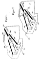
- Figure 1 illustrates a section of a microstructured surface of a Substrate 17.
- a channel 16 with a closed end (Wall) 16a formed groove (e.g. etched), the side walls 16s of which closed end 16a.
- the blunt end of the channel is in the Cross-section the smallest, with a view of all other channel cross-sections.
- the channel 16 can be designed conically onto the blunt with flat side walls 16s Run towards the end of 16a.
- a flow of liquid 12 is generated in the channel 16.
- the liquid flow can be generated via electrodes arranged in strips, with which high-frequency hiking fields are formed (see Publication from Journal of Micromechanics and Microengineering, Issue 4, 1994, Pages 217ff). Above a certain amplitude, local heating occurs Liquid over the strip-shaped electrodes, which electrodes in FIG. 1 are not shown, but can easily be supplemented mentally.
- the local Heating leads to a conductivity gradient above the electrodes, for example in the channel 16 shown, at the bottom of which the strip-shaped Electrodes are attached.
- electric fields - which are additionally induced - generate space charges which can be moved around in the mentioned electric traveling field To generate liquid flow in the channel 16.
- the conductivity gradient mentioned can also be formed over a differently induced temperature gradient namely by non-electrical means, e.g. by cooling on the bottom of the Channel 16 and heating at a distance from it on the top.
- a sperm 15 becomes high frequency electric field between alignment electrodes 11a and 11b and one Brake electrode 13 is generated, aligned and by the conical arrangement of the Electrodes 11 a, 11 b guided to the brake electrode 13 in a controlled manner.
- a detector e.g. optical, electrical
- the brake electrode 13 is switched off, it leaves Sperm the area in one direction, opposite to flow 12.
- the object 15 can be moved over the Chip surface OF are steered.
- the arrangement shown can be in different sizes and Arrangement modifications can be adapted to special cells.
- the substrate 17 can be glass, a semiconductor material, plastic or ceramic. Also other smooth, structurable surfaces are conceivable.
- the location-stable, contactless fixation works even when there is no counterflow 12 is generated, solely via an application of high-frequency electrical fields (Frequencies between 100 kHz and 1 GHz and amplitudes from a few 100 mV up to a few volts). With the high frequencies, the induced membrane potentials kept low. They are at the field strengths necessary for fixing the position in the Range of a few mV.
- the planar design of the electrodes 11 a, 11 b, 13 improved the heat dissipation in the liquid and in the substrate, while increasing the field gradient.
- Parts of the chip surface 17 can be structured or structured with a further substrate unstructured) are covered, so that closed microsystems are formed.
- the simplest case is a glass plate.
- Figure 2 shows a structure similar to Figure 1, with the difference that here there is a 3-dimensional structure in that two electrode levels (first level: 21a, 21b, 23a, 24a, 24b; second level: 21c, 21d, 23b ) were processed, which are spaced and isolated via structured spacers S to form a channel 26. These spacers S simultaneously produce a microchannel system 26. Again, a counterflow 22 can be used.
- the front end of the channel 26 is 26a, at which the spacers S end.
- the free sides of the spacers to the channel 26 form its side walls 26s.
- the sperm 25 is held in a quadrupole field trap 21a, 21b, 21c and 21d positioned in front of two spaced brake electrodes 23a and 23b.
- deflection electrodes 24a and 24b can be used.
- the chip can be open or covered and sealed with a plate (glass, semiconductors, etc.). about inserted openings or in the channel 26, a microcapillary can be inserted become. This would take the sperm with the hostage first and his Allow removal from the holder position.
- the electrical control of the guide electrodes 21, which taper conically, and the brake electrodes 23 in FIGS. 1 and 2 will be described together.
- the electrodes on the channels 16 and 26, which bring about the alignment and controlled supply of the sperm 15 to the brake electrode, are operated with AC voltage.
- the alignment electrodes 11a, 11b rest on the same phase and the brake electrode 13 on the other phase, the two phases being shifted by 180 ° with respect to one another.
- Rectangular, sinusoidal or triangular voltages are suitable as the voltage form, and other forms, in particular those composed of the aforementioned, can also be used.
- Periodic signals should be used for reliable operation.
- the arrangement according to FIG. 2 can be operated if the Electrodes 21a and 21b (in the first level) and the brake electrode 23b (in the second level) the voltage is applied with the first phase position and to the Electrodes 21d and 21c (in the second level) and the brake electrode 23a (in the first level) the voltage is applied with the phase position shifted by 180 °. Then the alternating field of Fig. 1 results, only stronger.
- Fig. 2 also opens the mode of operation to create a rotation field, the four Electrodes 21a-21d are operated with individual voltages, each at 90 ° are moved. If more than four electrodes are used, the result is necessary phase position from 360 ° divided by the number of electrodes.
- the Brake electrode is applied to the phase that one of the Alignment electrodes correspond to the same level, e.g. to the voltage according to the alignment electrode 21a with respect to the brake electrode 23a in the case of the four Alignment electrodes of Fig. 2.
- the one in the other plane Brake electrode 23b would be applied to the voltage, which is also the electrode 21c feeds.
- each Level adjacent electrode (21 b or 21 d) can be used.
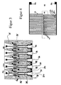
- Figure 3 is an example of a multiple implementation of the device shown in Figures 1 and 2.
- the alignment electrodes 31, the brake electrodes 33 and the deflection electrodes 34 are processed planar with the methods of semiconductor technology.
- the region 35 shown with dots can be a spacer, an insulator or another material that delimits the microchannels 36.
- the black squares 34b on the electrodes 34a are bonding areas.
- the microorganisms or unicellular organisms are guided into the channel system in a floating manner and guided by the converging electrodes 31, finally held by the front end section of the converging electrodes 31 and the adjacent front section of the brake electrode 33.
- the counterflow 32 can also be added.
- the single-celled organisms are released from the positioning, controlled by the upper electrodes 34a with bond pads 34b.
- the electrical connection via the bonding surfaces 34a to all electrodes 31, 34a, 33 takes place as in electronic circuits. Appropriate systems can be sterilized.
- FIG. 4 is a design of a positioning device for 15 individual objects 45.
- the substrate is designated by 42.
- the alignment electrodes 41 mounted thereon simultaneously form the single-channel boundary (for example, processing the electrodes with a thickness of a few micrometers).
- the brake electrodes 43, each ending between the front ends of the alignment electrodes, result in the cells 45 being lined up in the manner shown.
- Below or above the central area in which the ends of the electrodes are closely adjacent there is a detector 44 with which the swimming movement of individual or all objects 45 can be detected.
- a partial or complete closure / closure of the surface can be carried out.
Landscapes
- Life Sciences & Earth Sciences (AREA)
- Chemical & Material Sciences (AREA)
- Health & Medical Sciences (AREA)
- Engineering & Computer Science (AREA)
- Organic Chemistry (AREA)
- Wood Science & Technology (AREA)
- Zoology (AREA)
- Bioinformatics & Cheminformatics (AREA)
- Genetics & Genomics (AREA)
- General Health & Medical Sciences (AREA)
- Biotechnology (AREA)
- Microbiology (AREA)
- Molecular Biology (AREA)
- Biochemistry (AREA)
- General Engineering & Computer Science (AREA)
- Biomedical Technology (AREA)
- Proteomics, Peptides & Aminoacids (AREA)
- Sustainable Development (AREA)
- Cell Biology (AREA)
- Microelectronics & Electronic Packaging (AREA)
- Chemical Kinetics & Catalysis (AREA)
- Electrochemistry (AREA)
- Pathology (AREA)
- Physics & Mathematics (AREA)
- Analytical Chemistry (AREA)
- Biophysics (AREA)
- Immunology (AREA)
- Apparatus Associated With Microorganisms And Enzymes (AREA)
Description
- Figur 1
- ist eine ebene Gestaltung von Elektroden 11a,11b auf einem Substrat zur ortsstabilen Fixierung eines Einzellers 15.
- Figur 2
- ist eine mehrdimensionale Gestaltung von Elektroden 21 a,21 b,21 c,21 d.
- Figur 3
- ist eine Parallelschaltung der Brems- und Halteeinrichtung gemäß Figur 1 oder Figur 2.
- Figur 4
- ist eine Ausführung von Figur 1 ohne mechanische Nut 16, nur begrenzt durch jeweilige Ausrichtungselektroden 41a,41b.
Claims (12)
- Verfahren zur stabilen Positionierung oder zur Separation aktiv beweglicher Einzeller, in flüssigen Medien, wobei die Einzeller (15,25,45)(a) über eine oder mehrere im Mikrometerbereich langgestreckte Elektroden (11,21,31,41) mittels wechselnder oder wandernder hochfrequenter Felder ausgerichtet und abgebremst werden;(b) mit einer oder mehreren - in ihren typischen Abmessungen den Abmessungen der Ausrichtungs-Elektroden (11,21,31,41) entsprechenden - Bremselektroden (13,23,33,43) in ihrer Vorwärtsbewegung retardiert bis ganz aufgehalten werden, um in diesem Positionier-Zustand Organellenbewegung(en) registrieren und bewerten zu können oder selektiv einzelne Einzeller mittels einzubringender Mikroelemente entnehmen zu können.
- Verfahren nach Anspruch 1, dadurch gekennzeichnet, daß eine den Einzellern (15,25,45) entgegengerichtete Strömung (12,22,32) von außen oder über eine elektrische Ansteuerung der Mikroelektroden (11,21,31,41) erzeugt wird.
- Verfahren nach einem der vorigen Verfahrensansprüche, dadurch gekennzeichnet, daß zwei oder mehr Einzeller gleichzeitig positioniert oder zu Gruppen formiert werden.
- Verfahren nach einem der vorigen Verfahrensansprüche, bei dem die einzelnen Einzeller selektiv mittels Kapillaren entnommen werden.
- Verfahren nach einem der vorigen Verfahrensansprüche bei dem die Organellenbewegung die Bewegung von Geiseln, Cilien oder Flagellen (15a) ist.
- Verfahren nach einem der vorigen Verfahrensansprüche, dadurch gekennzeichnet, daß über miniaturisierte Ablenkelektroden (14,25,34) die Einzeller (15,24,45) nach ihrer Positionierung separiert oder aus ihrer Schwimmrichtung nach Entlassen aus der stabil gehaltenen Lage abgelenkt werden.
- Verfahren nach einem der vorigen Verfahrensansprüche, dadurch gekennzeichnet, daß in dem Bereich, in dem die antreibende Kraft der Einzellerbewegung gerade kompensiert wird, Detektoren (44) oder optische Fenster vorgesehen werden, mit denen die die Einzeller charakterisierenden Parameter, insbesondere die Quantifizierung ihrer Schwimmbewegung, erfaßt werden.
- Verfahren nach einem der vorigen Verfahrensansprüche, dadurch gekennzeichnet, daß einige der bewerieten Einzeller separiert und in ein abgetrenntes Mikrokompartiment überführt werden.
- Verfahren nach einem der vorigen Verfahrensansprüche, dadurch gekennzeichnet, daß die Bremselektroden (13,23,33,43) und Ablenkelektroden (14,24,34) über einen Computer oder Mikroprozessor angesteuert oder gesteuert werden.
- Verfahren nach einem der vorigen Verfahrensansprüche, dadurch gekennzeichnet, daß die elektrischen Wechselfelder oder wandernden Felder an den Elektroden (11a, 11b; 13) über Signale einer Frequenz groesser 0.1 MHz mit Amplituden zwischen 0,1 V und 40V erzeugt werden.
- Verfahren nach einem der vorigen Verfahrensansprüche, dadurch gekennzeichnet, daß als bewegliche Einzeller Bakterien oder Spermien der verschiedensten Tierarten oder menschliche Spermien eingesetzt werden.
- Verfahren nach einem der vorigen Verfahrensansprüche, dadurch gekennzeichnet, daß zusätzlich zu der elektrisch-hydrodynamischen Halterung der beweglichen Einzeller chemische oder optische Signale ausgesendet werden, um die Einzeller zu einer Richtungsänderung zu veranlassen.
Applications Claiming Priority (4)
| Application Number | Priority Date | Filing Date | Title |
|---|---|---|---|
| DE19602164 | 1996-01-22 | ||
| DE19602164 | 1996-01-22 | ||
| DE19605830 | 1996-02-16 | ||
| DE19605830A DE19605830C1 (de) | 1996-01-22 | 1996-02-16 | Lagestabile Positionierung aktiv beweglicher Einzeller |
Publications (2)
| Publication Number | Publication Date |
|---|---|
| EP0785428A1 EP0785428A1 (de) | 1997-07-23 |
| EP0785428B1 true EP0785428B1 (de) | 2004-04-07 |
Family
ID=26022246
Family Applications (1)
| Application Number | Title | Priority Date | Filing Date |
|---|---|---|---|
| EP97100865A Expired - Lifetime EP0785428B1 (de) | 1996-01-22 | 1997-01-21 | Lagestabile Positionierung aktiv beweglicher Einzeller |
Country Status (2)
| Country | Link |
|---|---|
| EP (1) | EP0785428B1 (de) |
| AT (1) | ATE263970T1 (de) |
Family Cites Families (3)
| Publication number | Priority date | Publication date | Assignee | Title |
|---|---|---|---|---|
| GB8926781D0 (en) * | 1989-11-27 | 1990-01-17 | Nat Res Dev | Identification of micro-organisms |
| DE4034697A1 (de) * | 1990-10-31 | 1992-05-14 | Fraunhofer Ges Forschung | Verfahren zur handhabung mikroskopisch kleiner, dielektrischer teilchen und vorrichtung zur durchfuehrung des verfahrens |
| DE4400955C2 (de) * | 1993-12-23 | 1999-04-01 | Fraunhofer Ges Forschung | Adhäsionssteuerbare Oberflächenstruktur |
-
1997
- 1997-01-21 AT AT97100865T patent/ATE263970T1/de not_active IP Right Cessation
- 1997-01-21 EP EP97100865A patent/EP0785428B1/de not_active Expired - Lifetime
Also Published As
| Publication number | Publication date |
|---|---|
| EP0785428A1 (de) | 1997-07-23 |
| ATE263970T1 (de) | 2004-04-15 |
Similar Documents
| Publication | Publication Date | Title |
|---|---|---|
| DE60010666T2 (de) | Verfahren und vorrichtung zur programmierbaren behandlung von fluiden | |
| EP1141264B1 (de) | Mikrosysteme zur zellpermeation und zellfusion | |
| DE69737552T2 (de) | Fraktionierung mittels dielektrophoresis und fraktionierung unter anwendung eines flussfeldes | |
| DE19928410C2 (de) | Gerätegehäuse mit einer Einrichtung zum Betrieb eines Labor-Mikrochips | |
| EP1603678B1 (de) | Verfahren und vorrichtung zur trennung von partikeln in einer flüssigkeitsströmung | |
| US6727451B1 (en) | Method and device for manipulating microparticles in fluid flows | |
| DE19928412C2 (de) | Versorgungselement für einen Labor-Mikrochip | |
| EP0555252B1 (de) | Verfahren zur handhabung mikroskopisch kleiner, dielektrischer teilchen und vorrichtung zur durchführung des verfahrens | |
| DE4400955C2 (de) | Adhäsionssteuerbare Oberflächenstruktur | |
| EP1042944B1 (de) | Verfahren und vorrichtung zur vermessung, kalibrierung und verwendung von laser-pinzetten | |
| EP1979738B1 (de) | Anordnung zur erzeugung von flüssigkeitsströmungen und/oder teilchenströmen, verfahren zu ihrer herstellung und zu ihrem betrieb sowie ihre verwendung | |
| EP0946709B1 (de) | Elektrodenanordnung für feldkäfige | |
| EP1720978B1 (de) | Magnetische manipulation von biologischen proben | |
| DE19605830C1 (de) | Lagestabile Positionierung aktiv beweglicher Einzeller | |
| WO2010076337A1 (de) | Elektromagnetisches mikrosystem zur manipulation magnetischer mikro- oder nanoperlen | |
| DE102011050254A1 (de) | Verfahren zur Separation polarisierbarer Biopartikel | |
| DE19500683B4 (de) | Trapping von Molekülen und Mikropartikeln in Feldkäfigen | |
| EP3831483A1 (de) | Verfahren zur konzentrierung von partikeln in einem tröpfchen unter verwendung eines ewod-geräts mit sensorgerät | |
| EP4188607B1 (de) | Verfahren und fluidisches mikrosystem zur dielektrophoretischen manipulierung von suspendierten partikeln | |
| EP0785428A1 (de) | Lagestabile Positionierung aktiv beweglicher Einzeller | |
| DE102006023238A1 (de) | Vorrichtung und Verfahren zur kontaktlosen Fixierung, Positionierung, Freigabe und Entnahme von Partikeln | |
| DE10127247B4 (de) | Vorrichtung und Verfahren zur elektrischen Behandlung suspendierter biologischer Partikel | |
| EP2185680B1 (de) | Vorrichtung und verfahren zur konditionierung biologischer zellen | |
| DE102004053596A1 (de) | Verfahren und Vorrichtungen zur Bearbeitung einzelner biologischer Zellen | |
| DE10117771A1 (de) | Verfahren und Vorrichtung zur Manipulation kleiner Flüssigkeitsmengen und/oder darin enthaltener Teilchen |
Legal Events
| Date | Code | Title | Description |
|---|---|---|---|
| PUAI | Public reference made under article 153(3) epc to a published international application that has entered the european phase |
Free format text: ORIGINAL CODE: 0009012 |
|
| AK | Designated contracting states |
Kind code of ref document: A1 Designated state(s): AT BE CH DE FR GB IE IT LI NL SE |
|
| RBV | Designated contracting states (corrected) |
Designated state(s): AT BE CH DE FR GB IE IT LI NL SE |
|
| 17P | Request for examination filed |
Effective date: 19980115 |
|
| 17Q | First examination report despatched |
Effective date: 20030310 |
|
| GRAP | Despatch of communication of intention to grant a patent |
Free format text: ORIGINAL CODE: EPIDOSNIGR1 |
|
| RAP1 | Party data changed (applicant data changed or rights of an application transferred) |
Owner name: EPPENDORF-NETHELER-HINZ GMBH Owner name: FRAUNHOFER-GESELLSCHAFT ZUR FOERDERUNG DERANGEWAND |
|
| GRAS | Grant fee paid |
Free format text: ORIGINAL CODE: EPIDOSNIGR3 |
|
| GRAA | (expected) grant |
Free format text: ORIGINAL CODE: 0009210 |
|
| AK | Designated contracting states |
Kind code of ref document: B1 Designated state(s): AT BE CH DE FR GB IE IT LI NL SE |
|
| REG | Reference to a national code |
Ref country code: GB Ref legal event code: FG4D Free format text: NOT ENGLISH |
|
| REG | Reference to a national code |
Ref country code: CH Ref legal event code: EP |
|
| REF | Corresponds to: |
Ref document number: 59711484 Country of ref document: DE Date of ref document: 20040513 Kind code of ref document: P |
|
| REG | Reference to a national code |
Ref country code: IE Ref legal event code: FG4D Free format text: GERMAN |
|
| REG | Reference to a national code |
Ref country code: SE Ref legal event code: TRGR |
|
| GBT | Gb: translation of ep patent filed (gb section 77(6)(a)/1977) |
Effective date: 20040714 |
|
| RAP2 | Party data changed (patent owner data changed or rights of a patent transferred) |
Owner name: FRAUNHOFER-GESELLSCHAFT ZUR FOERDERUNG DERANGEWAND Owner name: EPPENDORF AG |
|
| DX | Miscellaneous (deleted) | ||
| REG | Reference to a national code |
Ref country code: CH Ref legal event code: PFA Owner name: EPPENDORF AG Free format text: EPPENDORF-NETHELER-HINZ GMBH#BARKHAUSENWEG 1#D-22339 HAMBURG (DE) $ FRAUNHOFER-GESELLSCHAFT ZUR FOERDERUNG DER ANGEWANDTEN FORSCHUNG E.V.#HANSASTRASSE 27 C#80686 MUENCHEN (DE) -TRANSFER TO- EPPENDORF AG#BARKHAUSENWEG 1#22339 HAMBURG (DE) $ FRAUNHOFER-GESELLSCHAFT ZUR FOERDERUNG DER ANGEWANDTEN FORSCHUNG E.V.#HANSASTRASSE 27 C#80686 MUENCHEN (DE) Ref country code: CH Ref legal event code: NV Representative=s name: KELLER & PARTNER PATENTANWAELTE AG |
|
| NLT2 | Nl: modifications (of names), taken from the european patent patent bulletin |
Owner name: FRAUNHOFER-GESELLSCHAFT ZUR FOERDERUNG DER EN EPPE |
|
| NLT1 | Nl: modifications of names registered in virtue of documents presented to the patent office pursuant to art. 16 a, paragraph 1 |
Owner name: FRAUNHOFER-GESELLSCHAFT ZUR FOERDERUNG DER ANGEWAN Owner name: EPPENDORF AG |
|
| ET | Fr: translation filed | ||
| REG | Reference to a national code |
Ref country code: FR Ref legal event code: CD |
|
| PLBE | No opposition filed within time limit |
Free format text: ORIGINAL CODE: 0009261 |
|
| STAA | Information on the status of an ep patent application or granted ep patent |
Free format text: STATUS: NO OPPOSITION FILED WITHIN TIME LIMIT |
|
| 26N | No opposition filed |
Effective date: 20050110 |
|
| PGFP | Annual fee paid to national office [announced via postgrant information from national office to epo] |
Ref country code: IE Payment date: 20060105 Year of fee payment: 10 |
|
| PGFP | Annual fee paid to national office [announced via postgrant information from national office to epo] |
Ref country code: SE Payment date: 20060110 Year of fee payment: 10 |
|
| PGFP | Annual fee paid to national office [announced via postgrant information from national office to epo] |
Ref country code: NL Payment date: 20060116 Year of fee payment: 10 |
|
| PGFP | Annual fee paid to national office [announced via postgrant information from national office to epo] |
Ref country code: CH Payment date: 20060117 Year of fee payment: 10 |
|
| PGFP | Annual fee paid to national office [announced via postgrant information from national office to epo] |
Ref country code: BE Payment date: 20060123 Year of fee payment: 10 |
|
| PGFP | Annual fee paid to national office [announced via postgrant information from national office to epo] |
Ref country code: AT Payment date: 20060130 Year of fee payment: 10 |
|
| PG25 | Lapsed in a contracting state [announced via postgrant information from national office to epo] |
Ref country code: SE Free format text: LAPSE BECAUSE OF NON-PAYMENT OF DUE FEES Effective date: 20070122 Ref country code: IE Free format text: LAPSE BECAUSE OF NON-PAYMENT OF DUE FEES Effective date: 20070122 |
|
| PG25 | Lapsed in a contracting state [announced via postgrant information from national office to epo] |
Ref country code: LI Free format text: LAPSE BECAUSE OF NON-PAYMENT OF DUE FEES Effective date: 20070131 Ref country code: CH Free format text: LAPSE BECAUSE OF NON-PAYMENT OF DUE FEES Effective date: 20070131 |
|
| REG | Reference to a national code |
Ref country code: CH Ref legal event code: PL |
|
| EUG | Se: european patent has lapsed | ||
| NLV4 | Nl: lapsed or anulled due to non-payment of the annual fee |
Effective date: 20070801 |
|
| REG | Reference to a national code |
Ref country code: IE Ref legal event code: MM4A |
|
| PG25 | Lapsed in a contracting state [announced via postgrant information from national office to epo] |
Ref country code: AT Free format text: LAPSE BECAUSE OF NON-PAYMENT OF DUE FEES Effective date: 20070121 |
|
| BERE | Be: lapsed |
Owner name: *EPPENDORF A.G. Effective date: 20070131 Owner name: *FRAUNHOFER-GESELLSCHAFT ZUR FORDERUNG DER ANGEWAN Effective date: 20070131 |
|
| PG25 | Lapsed in a contracting state [announced via postgrant information from national office to epo] |
Ref country code: BE Free format text: LAPSE BECAUSE OF NON-PAYMENT OF DUE FEES Effective date: 20070131 |
|
| PG25 | Lapsed in a contracting state [announced via postgrant information from national office to epo] |
Ref country code: NL Free format text: LAPSE BECAUSE OF NON-PAYMENT OF DUE FEES Effective date: 20070801 |
|
| PGFP | Annual fee paid to national office [announced via postgrant information from national office to epo] |
Ref country code: GB Payment date: 20090130 Year of fee payment: 13 |
|
| PG25 | Lapsed in a contracting state [announced via postgrant information from national office to epo] |
Ref country code: IT Free format text: LAPSE BECAUSE OF NON-PAYMENT OF DUE FEES Effective date: 20080121 |
|
| PGFP | Annual fee paid to national office [announced via postgrant information from national office to epo] |
Ref country code: IT Payment date: 20090130 Year of fee payment: 13 Ref country code: DE Payment date: 20090331 Year of fee payment: 13 |
|
| PGFP | Annual fee paid to national office [announced via postgrant information from national office to epo] |
Ref country code: FR Payment date: 20090130 Year of fee payment: 13 |
|
| GBPC | Gb: european patent ceased through non-payment of renewal fee |
Effective date: 20100121 |
|
| REG | Reference to a national code |
Ref country code: FR Ref legal event code: ST Effective date: 20100930 |
|
| PG25 | Lapsed in a contracting state [announced via postgrant information from national office to epo] |
Ref country code: FR Free format text: LAPSE BECAUSE OF NON-PAYMENT OF DUE FEES Effective date: 20100201 |
|
| PG25 | Lapsed in a contracting state [announced via postgrant information from national office to epo] |
Ref country code: DE Free format text: LAPSE BECAUSE OF NON-PAYMENT OF DUE FEES Effective date: 20100803 |
|
| PG25 | Lapsed in a contracting state [announced via postgrant information from national office to epo] |
Ref country code: GB Free format text: LAPSE BECAUSE OF NON-PAYMENT OF DUE FEES Effective date: 20100121 |
|
| PG25 | Lapsed in a contracting state [announced via postgrant information from national office to epo] |
Ref country code: IT Free format text: LAPSE BECAUSE OF NON-PAYMENT OF DUE FEES Effective date: 20100121 |