EP0784006B1 - Winch assemblies with torque limiters - Google Patents
Winch assemblies with torque limiters Download PDFInfo
- Publication number
- EP0784006B1 EP0784006B1 EP97104501A EP97104501A EP0784006B1 EP 0784006 B1 EP0784006 B1 EP 0784006B1 EP 97104501 A EP97104501 A EP 97104501A EP 97104501 A EP97104501 A EP 97104501A EP 0784006 B1 EP0784006 B1 EP 0784006B1
- Authority
- EP
- European Patent Office
- Prior art keywords
- winch
- housing
- torque
- winch assembly
- torque limiter
- Prior art date
- Legal status (The legal status is an assumption and is not a legal conclusion. Google has not performed a legal analysis and makes no representation as to the accuracy of the status listed.)
- Expired - Lifetime
Links
- 230000000712 assembly Effects 0.000 title description 3
- 238000000429 assembly Methods 0.000 title description 3
- 230000007246 mechanism Effects 0.000 claims description 10
- 230000009471 action Effects 0.000 claims description 3
- 230000009467 reduction Effects 0.000 description 9
- 230000000717 retained effect Effects 0.000 description 4
- 238000000034 method Methods 0.000 description 3
- 239000004677 Nylon Substances 0.000 description 2
- 230000008859 change Effects 0.000 description 2
- 230000000694 effects Effects 0.000 description 2
- 239000002184 metal Substances 0.000 description 2
- 229920001778 nylon Polymers 0.000 description 2
- 239000013589 supplement Substances 0.000 description 2
- 230000003213 activating effect Effects 0.000 description 1
- WYTGDNHDOZPMIW-RCBQFDQVSA-N alstonine Natural products C1=CC2=C3C=CC=CC3=NC2=C2N1C[C@H]1[C@H](C)OC=C(C(=O)OC)[C@H]1C2 WYTGDNHDOZPMIW-RCBQFDQVSA-N 0.000 description 1
- 230000004888 barrier function Effects 0.000 description 1
- 238000003780 insertion Methods 0.000 description 1
- 230000037431 insertion Effects 0.000 description 1
- 238000004519 manufacturing process Methods 0.000 description 1
- 239000004033 plastic Substances 0.000 description 1
- 230000008569 process Effects 0.000 description 1
- 239000012858 resilient material Substances 0.000 description 1
- 230000004044 response Effects 0.000 description 1
- 238000000926 separation method Methods 0.000 description 1
- 239000012815 thermoplastic material Substances 0.000 description 1
- 239000013585 weight reducing agent Substances 0.000 description 1
- 238000003466 welding Methods 0.000 description 1
Images





Classifications
-
- B—PERFORMING OPERATIONS; TRANSPORTING
- B62—LAND VEHICLES FOR TRAVELLING OTHERWISE THAN ON RAILS
- B62D—MOTOR VEHICLES; TRAILERS
- B62D43/00—Spare wheel stowing, holding, or mounting arrangements
- B62D43/02—Spare wheel stowing, holding, or mounting arrangements external to the vehicle body
- B62D43/04—Spare wheel stowing, holding, or mounting arrangements external to the vehicle body attached beneath the vehicle body
- B62D43/045—Spare wheel stowing, holding, or mounting arrangements external to the vehicle body attached beneath the vehicle body the wheel or its cradle being attached to one or more chains or cables for handling
Definitions
- This invention relates to a winch assembly which can be used in releasing a tire carrier from a stored position in a vehicle, the carrier having been raised to that position by the winch.
- This is a division of 93922475.4 (EP-A-0662903) to which reference is made for other details.
- the invention can be used to store a load, such as a tire under a boat on a trailer, in a raised or stored position and finds particular application to a spare tire, the invention can be used generally, where it is desirable to secure a load in a raised or stored position.
- US-A-4325470 discloses a ratchet lever hoist which includes an overload clutch enclosed within the hoist handwheel.
- the handwheel is driven through a spline connection with the input drive hub of the hoist, and carries a plurality of first clutch disks.
- Second clutch disks are carried by a load brake member and frictionally engage the clutch disks through friction disks bonded to the second clutch disks.
- the clutch is preloaded to a torque capacity corresponding to the rated load of the hoist or a predetermined value over the rated load, such that the clutch will slip, preventing rotation of the load brake drive member when the torque capacity of the clutch is exceeded.
- a winch assembly comprises a winch housing and a torque limiter, the torque limiter being contained within a separate housing which is attachable to the winch housing.
- the torque limiter housing includes a flange and the winch housing includes a face on which are formed a plurality of clips. The torque housing can be pressed against this face so that the clips can be used to clip over the flange to hold the torque limiter against the winch housing.
- the torque limiter comprises a pair of plates and spring means for urging the plates into engagement with each other, such that rotation of one plate causes the other plate to rotate, provided that the torque between the two plates does not exceed a certain limit.
- the housing of the torque limiter is open on the side facing the winch assembly, whereby the attachment of the torque assembly to the winch housing tensions the spring means.
- the plates have engaging means disposed contacting surfaces and the spring means ensures engagement of the engaging means.
- One of the plates includes a nut portion for engagement with a handle, the other plate including means for engaging a drive mechanism of a winch in the winch housing.
- the spring means enables the engagement means to slip, at a predetermine torque, to provide overload protection for the winch.
- a safety device for securing a load carrier.
- the load carrier is moveable by operation of the winch assembly between a stored position and an accessible position remote from the stored position.
- the safety device comprises detent means, latching means moveable between a safety position, in which it is positioned with respect to the detent means when the load carrier is in the safety position, and a release position, where the load carrier is free to move to the accessible position.
- Operating means operate the latching means between the safety position and the accessible position.
- Activating means can be included which rotates to control the action of the operating means, such that the latching means is in the release position when the winch assembly is being operated to move the load from the stored position, and is in the safety position when the winch assembly is not being operated and the load carrier is in the stored position.
- FIG. 1 there is illustrated a vehicle V having a winch assembly 20 mounted therewith. Separate from the winch assembly is a torque limiter 30.
- the tire T is conveniently stored under the vehicle V until such time as a user may access the tire by lowering the tire using the crank handle 5 at the end 6 and inserting it to access the torque limiting device 30 attached to the winch 20. The tire T may then be moved in a direction D2 to lower the tire to the ground.
- Handle 5 is inserted in a direction D1 in the sleeve 40A wherein a latching mechanism generally referred to as 40 is disposed.
- the end of the handle 6 engages the cam surface 42a of the lever 40 which is connected to the rod 43 at the end 41.
- the rod 43 is connected to a latching mechanism 45 at the end 44 thereof. Therefore the latching mechanism 45 rotates in response to the movement of the lever 40 to disengage the shoulder 51 of the head of the shank portion 50 so that the tire carrier portion and the tire may be lowered to the ground.
- the assembly includes a mounted plate 29 to which a hollow cylinder 40a is attached, by attaching portions 40b to the bracket 29.
- winch 20 including a reel 25, and a housing 21 mounted to the mounting bracket 15 which winch 20 includes gear reduction portion 70 and 60 as best seen in Figures 5 and 6 which are used for speed reduction purposes.
- gear reduction portion 70 and 60 as best seen in Figures 5 and 6 which are used for speed reduction purposes.
- a resilient cable 28 is wound on to and off of the reel 25 by the rotation of the crank 5 in the required direction. Any winch structure would suffice and the details of the winch are not provided for this reason.
- the important portions of the invention are the lever portion 40 and the related latching portion 45 which are actuated by the insertion of the end 6 of the crank arm 5 through the cylinder 40a.
- a extension portion 17 Disposed below the mounting plate 29 is a extension portion 17.
- the shank portion 50a and the head 50 having shoulders 51 adjacent the shank portion 50a are contained within this frame portion 17 when the tire is retained in its stored position.
- the latching portion 45 therefore engages the shoulder portions 51 of the tire carrier 50 which retains the tire in the stored position should the cable 28 break. Further the latch mechanism assists carrying the load of the tire in the normal stored position.
- the tire T is attached to a rim T1 at flanges T2 as is typically known in the art.
- the tire is retained in the stored position by the latch 45 being secured to the shoulder 51 of the head affixed to the shank 50a and having a flange 53 extending underneath the rim T1.
- This flange 53 raises and lowers the tire T from the stored position to the accessible position as the cable 28 is wound out or wound in.
- a spring biased device 54 which abuts the flange 54a is provided to retain the correct tension in the unit. This is well known in the art.
- the rotation of the latch in direction D3 allows the release or latching of the shoulder portion 51 of the tire carrier 52.
- the tire is shown in the accessible position about to be cranked up to its stored position and latched when handle 5 is removed from the cylindrical portion 40a to release the detent portion 42a and thereby allow the latch portion to return to its locked position under the shoulder 51 of the carrier 52 wherein the fingers 49 lock under the shoulder 51 on the abutting arcuate surface 44 thereof wherein the tire is therefore in the latched position.
- the torque limiting device 30 is contained separately from the winch assembly 20. Therefore the torque limiting device 30 includes two halves 36a and 35a which contain the torque limiting plates 30a and 30B which engage at all times and are held in constant engagement by the belleville spring 31. Therefore the spring 31 and the plates 30a and 30b are contained between the two portion 36a and 35a
- the shaft 35 is affixed for example by welding to portion 35a.
- the portion 35a and the torque plates 30a and 30b are also pressed against the other halve of the housing 36a.
- the portions 37 are used for connecting the two plates 35a and 36a loosely together.
- the torque limiting plates 30a and 30b include a multiplicity of teeth, which at a predetermined torque, the plates slip with respect to one another and thus provide overload protection for the winch 20.
- the torque limiting device 30 is a supplement to any winch and it may provide an add on package for a winch which has no torque overload protection by merely inserting this package 30 on a convenient shaft in between the housing 20 and the handle.
- ring gear portions 60 stamped from a metal disk wherein the recess 65 including the teeth 65a are produced by stamping the ring gear 60 so as to raise a portion thereof out of the plane P1 of the ring gear 60.
- the planetary gear portion 70 includes teeth 75 which are formed by raising the teeth 75 out of the plane P2 of the planetary gear 70. In doing so a pocket is provided behind the section having the teeth 75 thereon. This therefore provides a simple method of forming a ring gear and a planetary gear which is easy to manufacture.
- taumel gear reductions portions including a ring gear 60 and an planetary gear 70 which are manufactured by a stamping process from flat circular plates and have teeth on the ring gear and teeth on the planetary gear which inter engage having been formed by metal stamping techniques. Generally there is one less tooth formed with the planetary gear than the ring gear to effect the taumel principle.
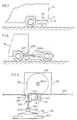
- Figures 7 and 8 illustrate winches 120 and 220, installed adjacent the bottom V1 and V2 of vehicles VA and VB, for moving a tire TA and TB from a stored position to an accessible position.
- Figure 8 illustrates a winch 220 installed at a distance from the tire TB separated therefrom by an cable access tube 228A. Further the winch 220 is disposed horizontally whereas winch 120 is disposed vertically.
- Handle 206 is provided in Figure 8 to rotate the winch 220.
- the winch 120 of Figure 7 the winch components being contained between the housing 121 and the backing plate 115 similar to the unit described in relation to Figures 2 and 3.
- Nut 135a is provided for access by the handle H at end 106a thereof.
- the winch 120 is attached to the bottom V1 of vehicle VA at 129 by exemplary mounting holes 115b so that the portions illustrated extend through the bottom 129 toward the tire TA.
- the flange 115a may be welded to the bottom 129 of the vehicle. In this manner the cable 128 may be lowered and raised securely to and from the stored and accessible positions.
- the tire carrier 150 is provided at one end of the cable and operates in a similar manner to the assembly of Figures 2 and 3 with the exceptions as will be described as follows.
- the backing plate 115 is formed from a single stamping which includes mounting portions 115b and 115a and flanges 115c and 115d.
- the portion 115c has a passage similar to that illustrated in Figure 2 to provide for the passage of cable 128.
- the winch 120 and the components thereof are housed within the cover 121 and the backing plate 115.
- the actuator 300 fixed in position by hexagonal threaded fastener 300a.
- the handle H2 is operated and is connected by arm H1 to end H3 wherein is disposed at opening 106a to engage end 135a of of spindle 135a.
- the actuator 300 will rotate in a counter clockwise direction (when viewed in relation to Figure 10)moving the rod end 181 towards the perimeter of the actuator which causes the lever arm 141a of lever 140 near the other end 182 of rod 180 to move about pivot 140a fixed to flange 115d of bracket 115.
- the leg 141 of lever 140 is fixed at 143b to rod 143 which in turn engages with openings 148a to locking member 148 which works substantially the same as item 48 of Figure 2 with the exception that item 148 moves in a more linear fashion than item 48 of Figure 2.
- a torsion spring 148b is provided to bias member 148 within windows 115f of flange 115c to the locked position. Therefore when the carrier is in the position shown in Figure 13 as the winch 120 is rotated the actuator is also rotated to move end 181 of rod 180 in the manner described above so as to remove the forks 149 sufficiently away from the carrier shoulder 151 to allow the cable 128 to be payed out and the tire to be moved to the accessible position.
- 15 and 16 cable 128 is anchored in slot 160a of circular plate 160 which plate forms one half of the winch reel R defined with the other reelplate 161.As shown the cable will therefore wind on the reel R in a clockwise direction (when observed from the housing end 121of Figure 14) in this embodiment only, and accumulates one layer above another on surface 160b when the winch is operated.
- a housing 121 is provided at one end of the winch components which is mounted via opening 121e (via fasteners not shown)to the bracket 115 also providing the other closing end of the winch 120.
- a spindle 135 therefore extends through the opening 121b of housing 121 and an opening 117 in the mounting plate 115 as best seen in Figure 15.
- a nut end 135a is therefore provided for access by the handle H or for engagement with a separate clip on torque limiter as best seen in Figures 14 and 15.
- the spindle 135 therefore passes through an opening 173 of gearplate 170 which has gears 175 provided therewith, having nine teeth.
- a tail portion 170a is provided with gearplate 170 to prevent the free rotation thereof in operation as best seen in Figure 16A.
- the spindle 135 therefore engages gearplate 170 proximate opening 173 at eccentric portion 135b of spindle 135, the opening 173 being slightly larger than the eccentric portion 135b. The eccentric portion therefore wobbles within the opening 173 or gearplate 170 in use.
- the spindle portion 135d therefore passes thereafter through, the opening 160d of reelplate 160,the opening 161b of reelplate 161, the opening 117 of bracket 115,and finally through the opening 300x of the disk shaped actuator 300 whereat a hexagonal threaded fastener 300a engages opening 135e, as best seen in Figure 15, thereby fastening and retaining all of the winch components.
- the reelplate 160 is constructed similarly to the structure illustrated in Figure 5 and has a ring gear 165 formed on the side thereof nearest the gearplate 170, as best seen in relation to Figure 16A, which has ten engaging teeth to engage the nine teeth 175 of gearplate 170.
- This difference of one tooth in the number of teeth between the gears 165 and 175 causes a speed reduction but increased torque in the operation of the winch which speed reduction principle is known and described in many winch assemblies in the prior art.
- the spindle 135 will also rotate in a clockwise direction; the eccentric portion 135b operating within the opening 173 of gearplate 170 with the nine teeth 175 engaging the ring gear teeth 165, numbered ten, of reelplate 160 thereby driving the reel R in a direction so as to takeup cable.
- the cable 128 is anchored in opening 160a of reelplate 160 via fastener 128a in a conventional manner. Therefore as the winch is operated the cable will be taken up in the clockwise direction and payed out in the counterclockwise direction. Of course this may be reversed in design.
- a resiliently biased arm 162 provided as a anti-backdriving feature for the winch 120.
- the arm 162 includes an arcuate side 162a which abuts in use the first coil of cable 128 and is retained in position by the first coil at position X,until the cable is payed out to the position Y in Figure 16B, whereat the arm 162 bei.
- the arm 162 includes a torsion spring 162d having two ends.
- the first end 162f extends along the arm in a long groove cut in the arm to ensure the proper biasing and motion of the arm, and the second end 162e extend towards the reelplate 160 and is anchored in an opening in reelplate 160(not shown).
- a pin extends through opening 162h to anchor the arm 162 to reelplate 161 at opening 161d.
- an arm such as arm 162 is taught in the art in United States Patent 2,053,976 issued September of 1936.
- a torque limiting unit 130 which fastens to the side of housing 121 by annular ring 121a which includes portions 121x which act as clips to fasten over flange 137a of torque limiter housing 137.
- the housing and the contents thereof when aligned so as to engages the end 135a of spindle 135 as shown therefore clips in position when the flange 137a is pressed over clips 121x causing the clips to flex downwardly until they pass the flange and clip thereover to retain the housing 137 in position.
- the clips are formed with the annular ring 121a of housing 121 with separations defined between the portions 121x and the ring 121a to allow the independent flexing of the clips.
- the torque limiter 130 is similar in design to that illustrated in Figures 1 through 6 with the exception that it is joined to the winch housing as a supplementary member utilizing one side of the winch housing 121 to act as a backing plate for housing 137 to retain the torque limiter components.A spring therefore is provided to ensure the engagement of the teeth 132, 133 disposed upon adjacent surfaces of of gears 130a and 130b as best seen in Figure 15.
- Member 130a also includes a nut portion 130e for engagement with the handle H in use.
- Member 130b includes a spindle engaging portion 133a to engage portion 135a of the spindle 135 and hence drive the winch 120 in the manner described previously.Therefore if the handle H accesses the nut 130 formed with the gear 130 via portion H3 thereof, H3 engages the seal H5 of the assembly (which is recommended as a barrier to dirt and moisture but is optional) and nut portion 130e of the torque limiter extending through opening 137b of the housing 137.
- the torque limiting plates 130a and 130b include the multiplicity of teeth 132 and 133, and at a predetermined torque, the plates slip with respect to one another and thus provide overload protection for the winch 120.
- the torque limiting device 130 is a supplement to any winch and it may provide an add on package for a winch which has no torque overload protection by merely inserting this package 130 on the winch housing thereof as illustrated in Figure 15 and described above.
- the balance of the winch assembly 120 and the operation thereof remains as described above.
- FIG. 16 there is illustrated a winch assembly as previously described with the exception that the actuator 300 replaces the reel plate 161 in defining reel R2 with reelplate 160. Otherwise the operation thereof is identical to previous descriptions of the assembly. However the embodiment of Figure 16 presents a more compact package.Further the torque limiting features illustrated and described in relation to Figure 15 may be incorporated therewith.
- FIG. 17 there is illustrated the winch assembly 220 as illustrated in relation to Figure 8 which separates the components previously described in order to provide a package which may be oriented horizontally. Therefore two mounting plates 215 and 216 are provided.
- the winch 220 being fastened in use to plate 215 at the bottom of the vehicle and including all of the features previously described including the actuator 300 for engagement with rod end 281 of rod 280.
- a tube 228a is provided to smoothly carry the cable 228 from the winch 220 to the tire carrier in a manner consistent with the previous descriptions.
- the rod 280 operates in a manner consistent with the operation of rod 180 described and illustrated above.
- the latch bracket 216 is mounted under the vehicle via opening 216e, and carries a latch 248 engageable in openings 216d disposed with downwardly extending bracket 216c in a manner as previously described.
- the rod end 282 rides in slots 248a in latch 248 which as previously described is resiliently biased to the latched position of the carrier by the torsion spring 248b.
- the rod 280 is guided by portion 215f and an equivalent portion on member 216(not shown) to ensure rod 280 travels in a substantially linear path to provide linear motion of latch 248 when engaging and disengaging the carrier head 150. Otherwise the operation of the winch 220 and rod 280 in relation to actuator 300 are consistent with the description in relation to Figures 9 through 15 above.
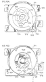
- FIG 16A there is illustrate the wobbling effect of plate 170 and the gears 175 thereof with respect to the ring gear 165 of reel plate 160 as driven by eccentric 135b of spindle 135.
- the plate 170 includes a tail portion 170a which is retained in area 121g of the space defined in housing 121 so as to prevent movement of the plate 170 beyond the bounds set by 121g. The motion of the eccentric will cause the gear 175 to drive the reelplate 160 at a speed reduction as is known and described above.
- the actuator 300 being molded from nylon or plastic with the opening 300x provided therewith for the fastening of the actuator in position as described previously.
- Substantially arcuate paths 301 and 302 are provided therewith to control the motion of rod end 181 (or 281) when the winch 120 (or 220) is operated.
- the paths 301 and 302 are defined between two substantially spiral shaped raised portions 305 which include a centre broad portion 315 and flexible flange portions 310 and 320 at the ends of the raised portions 305.Also provide to retain the rod end in use is a raised ring 308.
- the raised portions 305 therefore control the rod end 181 therebetween as the actuator 300 is rotated.
- the rod end therefore begins at the position as shown in Figure 18 proximate the centre of the actuator 300. If the actuator were rotated in a direction D1 the rod will remain in its position of Figure 18 and the flexible flanges 320 will flex outwardly away from the rod end 181 to allow it to pass in one direction only. However when the actuator 300 is rotated in the direction D2 it will be forced to move along the substantially spiral path 301 for one quarter of a turn, not being able to pass the flexible flange ends 320 of the actuator, until the rod end reaches a position near the perimeter of actuator 300.
- the rod end then travels in paths 303 and 304 bounded by the raised portions 305 and the raised collar 308, passing the flexible flanges 310 in one direction only.
- the continued rotation of the actuator retains the rod end 181 in the control paths 303 and 304.
- the rod 180 In moving the rod end 181 from near the centre of the actuator 300 to near the perimeter of the actuator 300, the rod 180 therefore has been moved an equivalent linear amount to the radius of the actuator so as to disengage the latch 148 form the carrier head shoulder 151 as previously described and to allow the lowering of the carrier and the tire to the accessible position.
- All of the components of the winch assemblies previously described may be manufactured from resilient materials such as nylon or other thermoplastic materials in order to reduce the weight of the assembly. However this is not essential. In doing so weight savings may be realized. Further the embodiments of the invention considerably reduce the number of components of the assembly and hence reduce the weight and increase the reliability thereof. For example a winch assembly of Figure 8 may be reduced from previously known structures from 43 parts in total to 28 parts,a 34% savings, at a weight reduction from 4.75 pounds to 3.5 pounds, a 26% savings in weight.
Landscapes
- Engineering & Computer Science (AREA)
- Chemical & Material Sciences (AREA)
- Combustion & Propulsion (AREA)
- Transportation (AREA)
- Mechanical Engineering (AREA)
- Transmission Devices (AREA)
- Fittings On The Vehicle Exterior For Carrying Loads, And Devices For Holding Or Mounting Articles (AREA)
- One-Way And Automatic Clutches, And Combinations Of Different Clutches (AREA)
- Mechanical Control Devices (AREA)
- Lock And Its Accessories (AREA)
- Tires In General (AREA)
- Portable Nailing Machines And Staplers (AREA)
- Mechanical Pencils And Projecting And Retracting Systems Therefor, And Multi-System Writing Instruments (AREA)
Abstract
Description
- This invention relates to a winch assembly which can be used in releasing a tire carrier from a stored position in a vehicle, the carrier having been raised to that position by the winch. This is a division of 93922475.4 (EP-A-0662903) to which reference is made for other details.
- Whilst the invention can be used to store a load, such as a tire under a boat on a trailer, in a raised or stored position and finds particular application to a spare tire, the invention can be used generally, where it is desirable to secure a load in a raised or stored position.
- US-A-4325470 discloses a ratchet lever hoist which includes an overload clutch enclosed within the hoist handwheel. The handwheel is driven through a spline connection with the input drive hub of the hoist, and carries a plurality of first clutch disks. Second clutch disks are carried by a load brake member and frictionally engage the clutch disks through friction disks bonded to the second clutch disks. The clutch is preloaded to a torque capacity corresponding to the rated load of the hoist or a predetermined value over the rated load, such that the clutch will slip, preventing rotation of the load brake drive member when the torque capacity of the clutch is exceeded.
- The invention is defined by the appended claims.
- In the invention, a winch assembly comprises a winch housing and a torque limiter, the torque limiter being contained within a separate housing which is attachable to the winch housing. According to an embodiment of the invention, the torque limiter housing includes a flange and the winch housing includes a face on which are formed a plurality of clips. The torque housing can be pressed against this face so that the clips can be used to clip over the flange to hold the torque limiter against the winch housing.
- In another embodiment of the invention, the torque limiter comprises a pair of plates and spring means for urging the plates into engagement with each other, such that rotation of one plate causes the other plate to rotate, provided that the torque between the two plates does not exceed a certain limit. The housing of the torque limiter is open on the side facing the winch assembly, whereby the attachment of the torque assembly to the winch housing tensions the spring means. The plates have engaging means disposed contacting surfaces and the spring means ensures engagement of the engaging means. One of the plates includes a nut portion for engagement with a handle, the other plate including means for engaging a drive mechanism of a winch in the winch housing. The spring means enables the engagement means to slip, at a predetermine torque, to provide overload protection for the winch.
- Preferably, a safety device is included for securing a load carrier. In this case, the load carrier is moveable by operation of the winch assembly between a stored position and an accessible position remote from the stored position. The safety device comprises detent means, latching means moveable between a safety position, in which it is positioned with respect to the detent means when the load carrier is in the safety position, and a release position, where the load carrier is free to move to the accessible position. Operating means operate the latching means between the safety position and the accessible position. Activating means can be included which rotates to control the action of the operating means, such that the latching means is in the release position when the winch assembly is being operated to move the load from the stored position, and is in the safety position when the winch assembly is not being operated and the load carrier is in the stored position.
- An embodiment of the invention will now be described with reference to Fig. 15 of the following drawings, in which drawings:
- Figure 1 is a side plan view of a vehicle upon which a winch assembly is installed;
- Figure 2 is a side plan view of a winch assembly of Figure 1 illustrating a latching mechanism thereof for securing a tire in a stored position under a vehicle;
- Figure 3 is a view similar to that of Figure 2 illustrating the action for unlatching the securing mechanism of the winch assembly of Figure 2 when a crank is inserted for operation of the winch;
- Figure 4 is a close up view of the latching portion illustrated in perspective and top plan view of the winch of Figure 1;
- Figures 5 and 6 are perspective and side views respectively of the reduction gears of the winch;
- Figures 7 and 8 are schematic illustrations of alternative arrangements;
- Figure 9 is a close-up side plan view of the arrangement illustrated in Fig. 7;
- Figure 10 is a perspective view of the arrangement illustrated in Figure 9;
- Figure 11 is an exploded perspective view of the arrangement illustrated in Figures 9 and 10;
- Figures 12 and 13 are schematic views of the latching of the carrier;
- Figure 14 is an exploded perspective view of an improved torque limiter of the assembly;
- Figure 15 is a cut-away view of the integrated assembly of an embodiment of the invention including the torque limiter of Figure 14;
- Figure 16 is a partially cut-away side plan view of a winch including an actuator contained within the housing of the winch;
- Figures 16A and 16B illustrate the operation of the winch of Figure 16;
- Figure 17 is a schematic perspective view of the assembly of Figure 8; and
- Figures 18 through 20 illustrate schematically the
actuator 300 of the previous illustrations and the operation thereof. -
- Referring now to Figure 1, there is illustrated a vehicle V having a
winch assembly 20 mounted therewith. Separate from the winch assembly is atorque limiter 30. The tire T is conveniently stored under the vehicle V until such time as a user may access the tire by lowering the tire using thecrank handle 5 at theend 6 and inserting it to access thetorque limiting device 30 attached to thewinch 20. The tire T may then be moved in a direction D2 to lower the tire to the ground.Handle 5 is inserted in a direction D1 in the sleeve 40A wherein a latching mechanism generally referred to as 40 is disposed. The end of thehandle 6 engages thecam surface 42a of thelever 40 which is connected to therod 43 at theend 41. Therod 43 is connected to alatching mechanism 45 at theend 44 thereof. Therefore thelatching mechanism 45 rotates in response to the movement of thelever 40 to disengage theshoulder 51 of the head of theshank portion 50 so that the tire carrier portion and the tire may be lowered to the ground. - The assembly includes a mounted
plate 29 to which ahollow cylinder 40a is attached, by attachingportions 40b to thebracket 29. When theend 6 of thecrank 5 therefore is inserted in thecylinder 40a endlever cam portion 42a whichlever 40 is pivoted atpivot 42, the use of which will be described hereinafter. Therefore theend 6 of thecrank 5 is inserted through to thehollow shaft portion 35 which receives theend 6 of thecrank handle 5. Thetorque limiter 30 therefore includes twoouter housing portions 35a and 36a. The half 35a includes thehollow shaft portion 35 whichhalf 35a connects to the half 36a which connects to theshaft 36 which continues on to thewinch portion 20. - The
shaft 36 then continues on to winch 20 including areel 25, and ahousing 21 mounted to the mounting bracket 15 whichwinch 20 includesgear reduction portion resilient cable 28 is wound on to and off of thereel 25 by the rotation of thecrank 5 in the required direction. Any winch structure would suffice and the details of the winch are not provided for this reason. The important portions of the invention are thelever portion 40 and therelated latching portion 45 which are actuated by the insertion of theend 6 of thecrank arm 5 through thecylinder 40a. - Disposed below the
mounting plate 29 is aextension portion 17. Theshank portion 50a and thehead 50 havingshoulders 51 adjacent theshank portion 50a are contained within thisframe portion 17 when the tire is retained in its stored position. Thelatching portion 45 therefore engages theshoulder portions 51 of thetire carrier 50 which retains the tire in the stored position should thecable 28 break. Further the latch mechanism assists carrying the load of the tire in the normal stored position. - The tire T is attached to a rim T1 at flanges T2 as is typically known in the art. The tire is retained in the stored position by the
latch 45 being secured to theshoulder 51 of the head affixed to theshank 50a and having aflange 53 extending underneath the rim T1. Thisflange 53 raises and lowers the tire T from the stored position to the accessible position as thecable 28 is wound out or wound in. A springbiased device 54 which abuts theflange 54a is provided to retain the correct tension in the unit. This is well known in the art. - When the
crank 5 is inserted toward thewinch 20 theend 6 of the crank arm passes through thesleeve 40a and abuts thelever 40 at thecam surface 42a thereof to causesuch lever 40 to rotate at itspivot 42 and causes therod 43 attached to the crank orlever 40 at theend 41 to move in a direction compatible to D1 and link with thelatch mechanism 45 atpoint 44. Therefore as therod 43 moves in the direction D1 it causes thelatch mechanism 45 pivoted at 46 viacam portion 47 to pivot in a direction D3 as best seen Figure 3. Therefore the lockingfingers 49 are removed from recess 17A of theframe portion 17 disengaging thefinger portions 49 from underneath theshoulder 51 of thehead portion 50 of thetire carrier 52. - The rotation of the latch in direction D3 allows the release or latching of the
shoulder portion 51 of thetire carrier 52. The tire is shown in the accessible position about to be cranked up to its stored position and latched whenhandle 5 is removed from thecylindrical portion 40a to release thedetent portion 42a and thereby allow the latch portion to return to its locked position under theshoulder 51 of thecarrier 52 wherein thefingers 49 lock under theshoulder 51 on the abuttingarcuate surface 44 thereof wherein the tire is therefore in the latched position. - Referring now to Figures 2 and 3 it can be readily seen that the
torque limiting device 30 is contained separately from thewinch assembly 20. Therefore thetorque limiting device 30 includes twohalves 36a and 35a which contain thetorque limiting plates 30a and 30B which engage at all times and are held in constant engagement by thebelleville spring 31. Therefore thespring 31 and theplates 30a and 30b are contained between the twoportion 36a and 35a Theshaft 35 is affixed for example by welding toportion 35a. Theportion 35a and thetorque plates 30a and 30b are also pressed against the other halve of the housing 36a. The portions 37 are used for connecting the twoplates 35a and 36a loosely together. Therefore when theshaft 5 atend 6 is inserted within the hollow of theshaft 35 and turned the housing portion 36a and theshaft 36 which engages thewinch 20 are also rotated. Thetorque limiting plates 30a and 30b include a multiplicity of teeth, which at a predetermined torque, the plates slip with respect to one another and thus provide overload protection for thewinch 20. Thetorque limiting device 30 is a supplement to any winch and it may provide an add on package for a winch which has no torque overload protection by merely inserting thispackage 30 on a convenient shaft in between thehousing 20 and the handle. - Referring now to figures 5 and 6 there are illustrated
ring gear portions 60 stamped from a metal disk wherein therecess 65 including theteeth 65a are produced by stamping thering gear 60 so as to raise a portion thereof out of the plane P1 of thering gear 60. Similarly theplanetary gear portion 70 includesteeth 75 which are formed by raising theteeth 75 out of the plane P2 of theplanetary gear 70. In doing so a pocket is provided behind the section having theteeth 75 thereon. This therefore provides a simple method of forming a ring gear and a planetary gear which is easy to manufacture. The ring and planetary gear inter fit as best shown in Figure 6 wherein theteeth 75 which extends laterally away from the plain P2 of thering gear 70 are inserted within theopening 65b of thering gear 60 so that theteeth 65 of the ring gear engage theteeth 75 of the planetary gear. Within thewinch 20 there is an offset which is inserted within the opening 63 of thering gear 60 so that the planetary gear may wobble about theopening 73 therein and thus provide gear reduction which is known as taumel gear reduction. Therefore within thewinch 20 there is provided taumel gear reductions portions including aring gear 60 and anplanetary gear 70 which are manufactured by a stamping process from flat circular plates and have teeth on the ring gear and teeth on the planetary gear which inter engage having been formed by metal stamping techniques.Generally there is one less tooth formed with the planetary gear than the ring gear to effect the taumel principle. - Figures 7 and 8 illustrate
winches winch 220 installed at a distance from the tire TB separated therefrom by ancable access tube 228A. Further thewinch 220 is disposed horizontally whereaswinch 120 is disposed vertically. Handle 206 is provided in Figure 8 to rotate thewinch 220. - Referring now to Figures 9, 10 and 11 there is illustrated the
winch 120 of Figure 7, the winch components being contained between thehousing 121 and thebacking plate 115 similar to the unit described in relation to Figures 2 and 3.Nut 135a is provided for access by the handle H atend 106a thereof.Thewinch 120 is attached to the bottom V1 of vehicle VA at 129 by exemplary mountingholes 115b so that the portions illustrated extend through the bottom 129 toward the tire TA. Alternatively theflange 115a may be welded to thebottom 129 of the vehicle. In this manner thecable 128 may be lowered and raised securely to and from the stored and accessible positions. Thetire carrier 150 is provided at one end of the cable and operates in a similar manner to the assembly of Figures 2 and 3 with the exceptions as will be described as follows. - The
backing plate 115 is formed from a single stamping which includes mountingportions flanges portion 115c has a passage similar to that illustrated in Figure 2 to provide for the passage ofcable 128. Thewinch 120 and the components thereof are housed within thecover 121 and thebacking plate 115. On the other side of the backing plate is provided theactuator 300 fixed in position by hexagonal threadedfastener 300a. As best seen in Figures 18 through 20 there is provided on the side of the actuatornearest bracket 115 substantially spiral shapedcontrol paths serpentine rod 180 is disposed. When thewinch 120 is operated by the handle H, theactuator 300 is also rotated. The handle H2 is operated and is connected by arm H1 to end H3 wherein is disposed at opening 106a to engageend 135a of of spindle 135a. When thewinch 120 is operated in a clockwise direction thereby paying out thecable 128, theactuator 300 will rotate in a counter clockwise direction (when viewed in relation to Figure 10)moving therod end 181 towards the perimeter of the actuator which causes thelever arm 141a oflever 140 near theother end 182 ofrod 180 to move aboutpivot 140a fixed toflange 115d ofbracket 115. Theleg 141 oflever 140 is fixed at 143b torod 143 which in turn engages withopenings 148a to lockingmember 148 which works substantially the same asitem 48 of Figure 2 with the exception thatitem 148 moves in a more linear fashion thanitem 48 of Figure 2. Atorsion spring 148b is provided tobias member 148 withinwindows 115f offlange 115c to the locked position. Therefore when the carrier is in the position shown in Figure 13 as thewinch 120 is rotated the actuator is also rotated to moveend 181 ofrod 180 in the manner described above so as to remove theforks 149 sufficiently away from thecarrier shoulder 151 to allow thecable 128 to be payed out and the tire to be moved to the accessible position. When thewinch 120 is rotated back to the stored position, after a tire change and presumably with a repaired tire thereon, therod end 181 will be moved alongpaths centre nut 300a returning the forkedportions 149 to the latched position. As thecarrier 155 returns to the latched position thehead 150 abuts the taperedsurface 149a offorks 149 atcam surface 150a thereby forcing theforks 149 away from thehead 150 as best seen in Figure 12 until the forks are free to return under theshoulders 151 ofhead 150 as best seen in Figure 13,being biased to do so bytorsion spring 148b. - As best seen in Figures 14, 15 and 16
cable 128 is anchored inslot 160a ofcircular plate 160 which plate forms one half of the winch reel R defined with the other reelplate 161.As shown the cable will therefore wind on the reel R in a clockwise direction (when observed from the housing end 121of Figure 14) in this embodiment only, and accumulates one layer above another onsurface 160b when the winch is operated. Ahousing 121 is provided at one end of the winch components which is mounted viaopening 121e (via fasteners not shown)to thebracket 115 also providing the other closing end of thewinch 120. Aspindle 135 therefore extends through theopening 121b ofhousing 121 and anopening 117 in the mountingplate 115 as best seen in Figure 15. Anut end 135a is therefore provided for access by the handle H or for engagement with a separate clip on torque limiter as best seen in Figures 14 and 15. Thespindle 135 therefore passes through anopening 173 ofgearplate 170 which hasgears 175 provided therewith, having nine teeth. Atail portion 170a is provided withgearplate 170 to prevent the free rotation thereof in operation as best seen in Figure 16A. Thespindle 135 therefore engagesgearplate 170proximate opening 173 ateccentric portion 135b ofspindle 135, theopening 173 being slightly larger than theeccentric portion 135b. The eccentric portion therefore wobbles within theopening 173 orgearplate 170 in use. - As best seen in Figure 15 the
spindle portion 135d therefore passes thereafter through, theopening 160d ofreelplate 160,theopening 161b ofreelplate 161, theopening 117 ofbracket 115,and finally through theopening 300x of the disk shapedactuator 300 whereat a hexagonal threadedfastener 300a engages opening 135e, as best seen in Figure 15, thereby fastening and retaining all of the winch components. - The
reelplate 160 is constructed similarly to the structure illustrated in Figure 5 and has aring gear 165 formed on the side thereof nearest thegearplate 170, as best seen in relation to Figure 16A, which has ten engaging teeth to engage the nineteeth 175 ofgearplate 170. This difference of one tooth in the number of teeth between thegears spindle 135 will also rotate in a clockwise direction; theeccentric portion 135b operating within theopening 173 ofgearplate 170 with the nineteeth 175 engaging thering gear teeth 165, numbered ten, ofreelplate 160 thereby driving the reel R in a direction so as to takeup cable. - The
cable 128 is anchored in opening 160a ofreelplate 160 via fastener 128a in a conventional manner. Therefore as the winch is operated the cable will be taken up in the clockwise direction and payed out in the counterclockwise direction. Of course this may be reversed in design. As best seen in relation to Figures 11 and 16B there is provided as a part of the bottom 160b of reel R, a resilientlybiased arm 162 provided as a anti-backdriving feature for thewinch 120. Thearm 162 includes anarcuate side 162a which abuts in use the first coil ofcable 128 and is retained in position by the first coil at position X,until the cable is payed out to the position Y in Figure 16B, whereat thearm 162 bei. resiliently biased outward bytorsion spring 162d upon further rotation of the winch engages thedetent 121h of thehousing 121 at 162b thereby preventing the further rotation of the reel R and the risk of the- winch backdriving and taking up cable with the further rotation of thewinch 120 thereby damaging the cable. Thearm 162 includes atorsion spring 162d having two ends. Thefirst end 162f extends along the arm in a long groove cut in the arm to ensure the proper biasing and motion of the arm, and the second end 162e extend towards thereelplate 160 and is anchored in an opening in reelplate 160(not shown). A pin extends through opening 162h to anchor thearm 162 to reelplate 161 at opening 161d.Generally an arm such asarm 162 is taught in the art in United States Patent 2,053,976 issued September of 1936. - Referring now to Figures 14 and 15 there is illustrated the same winch structure of Figures 9 through 13 with the addition that a
torque limiting unit 130 is provided which fastens to the side ofhousing 121 byannular ring 121a which includesportions 121x which act as clips to fasten overflange 137a oftorque limiter housing 137. The housing and the contents thereof when aligned so as to engages theend 135a ofspindle 135 as shown therefore clips in position when theflange 137a is pressed overclips 121x causing the clips to flex downwardly until they pass the flange and clip thereover to retain thehousing 137 in position. The clips are formed with theannular ring 121a ofhousing 121 with separations defined between theportions 121x and thering 121a to allow the independent flexing of the clips. - The
torque limiter 130 is similar in design to that illustrated in Figures 1 through 6 with the exception that it is joined to the winch housing as a supplementary member utilizing one side of thewinch housing 121 to act as a backing plate forhousing 137 to retain the torque limiter components.A spring therefore is provided to ensure the engagement of theteeth gears Member 130a also includes anut portion 130e for engagement with the handle H inuse.Member 130b includes aspindle engaging portion 133a to engageportion 135a of thespindle 135 and hence drive thewinch 120 in the manner described previously.Therefore if the handle H accesses thenut 130 formed with thegear 130 via portion H3 thereof, H3 engages the seal H5 of the assembly (which is recommended as a barrier to dirt and moisture but is optional) andnut portion 130e of the torque limiter extending throughopening 137b of thehousing 137. As the handle H is rotated thenut 130e will cause thegear 130a to rotate which because of the engagement ofteeth gear 130b to rotate which will in turn causespindle end 135a to rotate as engaged byportion 133a ofgear 130b. Theteeth belleville spring 131 which under normal operating conditions ensure the engagement ofteeth torque limiting plates teeth winch 120. Thetorque limiting device 130 is a supplement to any winch and it may provide an add on package for a winch which has no torque overload protection by merely inserting thispackage 130 on the winch housing thereof as illustrated in Figure 15 and described above. The balance of thewinch assembly 120 and the operation thereof remains as described above. - Referring now to Figure 16 there is illustrated a winch assembly as previously described with the exception that the
actuator 300 replaces thereel plate 161 in defining reel R2 withreelplate 160. Otherwise the operation thereof is identical to previous descriptions of the assembly. However the embodiment of Figure 16 presents a more compact package.Further the torque limiting features illustrated and described in relation to Figure 15 may be incorporated therewith. - Referring now to Figure 17 there is illustrated the
winch assembly 220 as illustrated in relation to Figure 8 which separates the components previously described in order to provide a package which may be oriented horizontally. Therefore two mountingplates winch 220 being fastened in use to plate 215 at the bottom of the vehicle and including all of the features previously described including theactuator 300 for engagement withrod end 281 of rod 280. Atube 228a is provided to smoothly carry thecable 228 from thewinch 220 to the tire carrier in a manner consistent with the previous descriptions. The rod 280 operates in a manner consistent with the operation ofrod 180 described and illustrated above. Thelatch bracket 216 is mounted under the vehicle viaopening 216e, and carries alatch 248 engageable inopenings 216d disposed with downwardly extendingbracket 216c in a manner as previously described. Therod end 282 rides in slots 248a inlatch 248 which as previously described is resiliently biased to the latched position of the carrier by thetorsion spring 248b. The rod 280 is guided byportion 215f and an equivalent portion on member 216(not shown) to ensure rod 280 travels in a substantially linear path to provide linear motion oflatch 248 when engaging and disengaging thecarrier head 150. Otherwise the operation of thewinch 220 and rod 280 in relation toactuator 300 are consistent with the description in relation to Figures 9 through 15 above. - Referring now to Figure 16A there is illustrate the wobbling effect of
plate 170 and thegears 175 thereof with respect to thering gear 165 ofreel plate 160 as driven by eccentric 135b ofspindle 135. Theplate 170 includes atail portion 170a which is retained in area 121g of the space defined inhousing 121 so as to prevent movement of theplate 170 beyond the bounds set by 121g.The motion of the eccentric will cause thegear 175 to drive thereelplate 160 at a speed reduction as is known and described above. - Referring now to Figure 18 through 20 and Figures 14, 15 and 16 there is illustrated the
actuator 300 being molded from nylon or plastic with theopening 300x provided therewith for the fastening of the actuator in position as described previously.Substantiallyarcuate paths paths portions 305 which include a centrebroad portion 315 andflexible flange portions ring 308. The raisedportions 305 therefore control therod end 181 therebetween as theactuator 300 is rotated. For example when the tire is in the stored position and thelatch 148 latches thecarrier head 150, it may be desired to to lower the tire for access. The rod end therefore begins at the position as shown in Figure 18 proximate the centre of theactuator 300. If the actuator were rotated in a direction D1 the rod will remain in its position of Figure 18 and theflexible flanges 320 will flex outwardly away from therod end 181 to allow it to pass in one direction only. However when theactuator 300 is rotated in the direction D2 it will be forced to move along the substantiallyspiral path 301 for one quarter of a turn, not being able to pass the flexible flange ends 320 of the actuator, until the rod end reaches a position near the perimeter ofactuator 300. The rod end then travels inpaths portions 305 and the raisedcollar 308, passing theflexible flanges 310 in one direction only. The continued rotation of the actuator retains therod end 181 in thecontrol paths rod end 181 from near the centre of theactuator 300 to near the perimeter of theactuator 300, therod 180 therefore has been moved an equivalent linear amount to the radius of the actuator so as to disengage thelatch 148 form thecarrier head shoulder 151 as previously described and to allow the lowering of the carrier and the tire to the accessible position. Therefore continued rotation of the winch will not change the position of therod end 181 until such time as the tire is returned to the stored position and the actuator is rotated in direction D1 whereat therod end 181 will not be able to pass theflexible flange 310 and will be forced to return alongarcuate path actuator 300 whereat therod end 181 will pass theflexible flanges 320 continually until the tire is raised and latched as described previously in relation to Figures 12 and 13. - All of the components of the winch assemblies previously described may be manufactured from resilient materials such as nylon or other thermoplastic materials in order to reduce the weight of the assembly. However this is not essential. In doing so weight savings may be realized. Further the embodiments of the invention considerably reduce the number of components of the assembly and hence reduce the weight and increase the reliability thereof. For example a winch assembly of Figure 8 may be reduced from previously known structures from 43 parts in total to 28 parts,a 34% savings, at a weight reduction from 4.75 pounds to 3.5 pounds, a 26% savings in weight.
Claims (7)
- A winch assembly comprising a winch housing (120) and a torque limiter (130) characterized in that the torque limiter (130) is contained within a separate housing (137) and is attached to the winch housing (121).
- A winch assembly according to Claim 1, wherein the torque limiter housing (137) includes a flange (137a) and the winch housing (121) includes a face having a plurality of clips (121x) formed thereon which, when the torque housing (137) is pressed there against, clip over the flange (137a) to hold the torque limiter (131) against the winch housing (121).
- A winch assembly according to Claim 1 or 2, wherein the torque limiter (130) comprises a pair of plates (130a, 130b) and spring means (131) for urging the plates into engagement with each other such that rotation of one plate (130b) causes the other plate (130a) to rotate, provided that the torque between the two plates does not exceed a certain limit; the housing of the torque limiter (130) being open on the side facing the winch assembly, whereby the attachment of the torque assembly to the winch housing tensions the spring means.
- A winch assembly according to Claim 3 wherein said plates have engaging means (132, 133) disposed upon contacting surfaces thereof, said spring means (131) ensuring engagement of said engaging means (132, 133); one of the plates (130a) also including a nut portion (130e) for engagement with a handle (H3), the other plate (130b) including means (133b) for engaging a drive mechanism (135) of a winch in the winch housing (121); said spring means (131) enabling the engagement means to slip, at a predetermined torque, to provide overload protection for said winch.
- A winch assembly according to any previous claim including a safety device (148) for securing a load carrier (155).
- A winch assembly according to Claim 5 wherein the load carrier (155) is moveable by operation of the winch assembly between a stored position and an accessible position remote from the stored position, and the safety device comprises:detent means (151);latching means (148) moveable between (a) a safety position, in which it is positioned with respect to said detent means (151) when the load carrier (155) is in the safety position, and (b) a release position, where the load carrier is free to move to the accessible position; andoperating means (180) for operating the latching means (148) between the safety position and the accessible position.
- A winch assembly according to Claim 6 further comprising actuating means (300) which rotates to control the action of the operating means (180), such that the latching means (148) is in the release position when the winch assembly is being operated to move the load from the stored position, and is in the safety position when the winch assembly is not being operated and the load carrier (155) is in the stored position.
Applications Claiming Priority (3)
| Application Number | Priority Date | Filing Date | Title |
|---|---|---|---|
| CA2079948 | 1992-10-06 | ||
| CA002079948A CA2079948C (en) | 1992-10-06 | 1992-10-06 | Safety latch for a tire carrier and improvements therefor |
| EP93922475A EP0662903B1 (en) | 1992-10-06 | 1993-10-06 | Safety latch for a tire carrier |
Related Parent Applications (2)
| Application Number | Title | Priority Date | Filing Date |
|---|---|---|---|
| EP93922475A Division EP0662903B1 (en) | 1992-10-06 | 1993-10-06 | Safety latch for a tire carrier |
| EP93922475.4 Division | 1994-04-14 |
Publications (2)
| Publication Number | Publication Date |
|---|---|
| EP0784006A1 EP0784006A1 (en) | 1997-07-16 |
| EP0784006B1 true EP0784006B1 (en) | 2001-08-22 |
Family
ID=4150501
Family Applications (2)
| Application Number | Title | Priority Date | Filing Date |
|---|---|---|---|
| EP93922475A Expired - Lifetime EP0662903B1 (en) | 1992-10-06 | 1993-10-06 | Safety latch for a tire carrier |
| EP97104501A Expired - Lifetime EP0784006B1 (en) | 1992-10-06 | 1993-10-06 | Winch assemblies with torque limiters |
Family Applications Before (1)
| Application Number | Title | Priority Date | Filing Date |
|---|---|---|---|
| EP93922475A Expired - Lifetime EP0662903B1 (en) | 1992-10-06 | 1993-10-06 | Safety latch for a tire carrier |
Country Status (6)
| Country | Link |
|---|---|
| EP (2) | EP0662903B1 (en) |
| AT (2) | ATE164357T1 (en) |
| AU (1) | AU5146893A (en) |
| CA (2) | CA2079948C (en) |
| DE (2) | DE69317666T2 (en) |
| WO (1) | WO1994007735A2 (en) |
Cited By (2)
| Publication number | Priority date | Publication date | Assignee | Title |
|---|---|---|---|---|
| US9315224B2 (en) | 2013-09-11 | 2016-04-19 | Batz, S. Coop. | Spare wheel pickup assembly |
| US9764783B2 (en) | 2013-09-11 | 2017-09-19 | Batz, S.Coop. | Spare wheel pickup assembly |
Families Citing this family (8)
| Publication number | Priority date | Publication date | Assignee | Title |
|---|---|---|---|---|
| CA2365408C (en) * | 1994-07-18 | 2002-10-29 | Tka Fabco Corp. | Safety latch for a tire carrier and improvements therefor |
| GB9523143D0 (en) * | 1995-11-11 | 1996-01-10 | Metallifacture Ltd | Vehicle wheel suspension assembly and winch |
| IL130974A0 (en) * | 1999-07-15 | 2001-01-28 | Mag Eh Ltd | Load securing device |
| ES2216685B1 (en) * | 2002-07-29 | 2006-02-16 | Batz S.Coop. | HITCH SYSTEM OF AN ANSWER WHEEL. |
| FR2867744B1 (en) * | 2004-03-16 | 2006-06-23 | Renault Sas | MOTOR VEHICLE HAVING A WHEEL EMERGENCY MOUNTED BY A WINCH |
| ES2527897B2 (en) * | 2013-07-29 | 2016-06-29 | Batz, S.Coop. | Gear assembly for a spare wheel collection unit, and spare wheel collection unit comprising said gear set |
| ES1172158Y (en) * | 2016-11-24 | 2017-03-07 | Fantek Ind S L | WINCH SAFETY DEVICE |
| DE102023121040A1 (en) * | 2023-08-08 | 2025-02-13 | Oechsler Ag | Gear component, planetary gear, actuator, use and method for producing an actuator |
Family Cites Families (11)
| Publication number | Priority date | Publication date | Assignee | Title |
|---|---|---|---|---|
| CH313223A (en) * | 1951-10-08 | 1956-03-31 | Puetzer Hans | Slipping clutch designed as overload protection on conveyors |
| DE1020539B (en) * | 1955-12-02 | 1957-12-05 | Ford Werke Ag | Spare wheel carrier on motor vehicles |
| JPS5123171Y2 (en) * | 1971-12-30 | 1976-06-15 | ||
| DE2557077C3 (en) * | 1975-12-18 | 1978-06-29 | Bayerische Motoren Werke Ag, 8000 Muenchen | Operating device for a transmission element in motor vehicles |
| US4325470A (en) * | 1980-02-15 | 1982-04-20 | Eaton Corporation | Hoist overload clutch |
| US4625947A (en) * | 1984-07-02 | 1986-12-02 | Deuer Manufacturing, Inc. | Tire lift/carrier |
| JPS6487960A (en) * | 1987-09-30 | 1989-04-03 | Toshiba Corp | Cam mechanism |
| US4884785A (en) * | 1988-08-26 | 1989-12-05 | Deuer Manufacturing Inc. | Apparatus for securing a spare tire on a vehicle |
| GB9027002D0 (en) * | 1990-12-12 | 1991-01-30 | Metallifacture Ltd | Winching device |
| EP0501644B1 (en) * | 1991-02-28 | 1997-08-06 | Ford Motor Company Limited | Winches |
| US5111715A (en) * | 1991-07-03 | 1992-05-12 | General Motors Corporation | Window motor attachment to vehicle door |
-
1992
- 1992-10-06 CA CA002079948A patent/CA2079948C/en not_active Expired - Fee Related
- 1992-10-06 CA CA002191258A patent/CA2191258C/en not_active Expired - Fee Related
-
1993
- 1993-10-06 DE DE69317666T patent/DE69317666T2/en not_active Expired - Fee Related
- 1993-10-06 DE DE69330648T patent/DE69330648T2/en not_active Expired - Fee Related
- 1993-10-06 EP EP93922475A patent/EP0662903B1/en not_active Expired - Lifetime
- 1993-10-06 AU AU51468/93A patent/AU5146893A/en not_active Abandoned
- 1993-10-06 AT AT93922475T patent/ATE164357T1/en not_active IP Right Cessation
- 1993-10-06 EP EP97104501A patent/EP0784006B1/en not_active Expired - Lifetime
- 1993-10-06 AT AT97104501T patent/ATE204545T1/en not_active IP Right Cessation
- 1993-10-06 WO PCT/CA1993/000421 patent/WO1994007735A2/en not_active Ceased
Cited By (2)
| Publication number | Priority date | Publication date | Assignee | Title |
|---|---|---|---|---|
| US9315224B2 (en) | 2013-09-11 | 2016-04-19 | Batz, S. Coop. | Spare wheel pickup assembly |
| US9764783B2 (en) | 2013-09-11 | 2017-09-19 | Batz, S.Coop. | Spare wheel pickup assembly |
Also Published As
| Publication number | Publication date |
|---|---|
| WO1994007735A2 (en) | 1994-04-14 |
| WO1994007735A3 (en) | 1994-06-09 |
| EP0662903A1 (en) | 1995-07-19 |
| CA2079948C (en) | 1998-07-14 |
| DE69330648D1 (en) | 2001-09-27 |
| ATE204545T1 (en) | 2001-09-15 |
| EP0784006A1 (en) | 1997-07-16 |
| DE69330648T2 (en) | 2002-06-27 |
| CA2191258A1 (en) | 1994-04-07 |
| ATE164357T1 (en) | 1998-04-15 |
| DE69317666D1 (en) | 1998-04-30 |
| EP0662903B1 (en) | 1998-03-25 |
| DE69317666T2 (en) | 1998-10-15 |
| CA2079948A1 (en) | 1994-04-07 |
| AU5146893A (en) | 1994-04-26 |
| CA2191258C (en) | 1998-07-21 |
Similar Documents
| Publication | Publication Date | Title |
|---|---|---|
| CA2365408C (en) | Safety latch for a tire carrier and improvements therefor | |
| US5188341A (en) | Safety latch for a tire carrier | |
| US5669116A (en) | Shoe closure | |
| US6925757B2 (en) | Cable drive assembly | |
| US6293522B2 (en) | Safety latch for a tire carrier and improvements therefor | |
| US4422522A (en) | Inertial lock for vehicle door latch | |
| EP0662903B1 (en) | Safety latch for a tire carrier | |
| US4155233A (en) | Deck lid lock safety release | |
| US5027931A (en) | Brake/shift interlock for an automatic transmission shift control mechanism | |
| GB2282408A (en) | Dual throat latch assembly | |
| US6390452B1 (en) | Safety latch for a tire carrier and improvements therefor | |
| US5415377A (en) | Sheave assembly for a tire lift/carrier winch | |
| US6282980B1 (en) | Self-adjusting parking brake actuator | |
| US20100171326A1 (en) | Lockable handle assembly | |
| JPS62173352A (en) | Tension removing device for car safety belt container | |
| US6547219B2 (en) | Safety latch for a tire carrier and improvements therefor | |
| EP0501644B1 (en) | Winches | |
| CA2154087C (en) | Safety latch for a tire carrier and improvements therefor | |
| GB2253198A (en) | Winches | |
| JPS645670Y2 (en) | ||
| JPH041260Y2 (en) | ||
| JP2001287741A (en) | Loading device | |
| JPH0680917U (en) | Tilt hinge | |
| JPH0742882Y2 (en) | Suspension structure of spiral spring | |
| JPH1061292A (en) | Horseshoe lock |
Legal Events
| Date | Code | Title | Description |
|---|---|---|---|
| PUAI | Public reference made under article 153(3) epc to a published international application that has entered the european phase |
Free format text: ORIGINAL CODE: 0009012 |
|
| AC | Divisional application: reference to earlier application |
Ref document number: 662903 Country of ref document: EP |
|
| AK | Designated contracting states |
Kind code of ref document: A1 Designated state(s): AT DE FR GB IT |
|
| 17P | Request for examination filed |
Effective date: 19970922 |
|
| 17Q | First examination report despatched |
Effective date: 19990105 |
|
| GRAG | Despatch of communication of intention to grant |
Free format text: ORIGINAL CODE: EPIDOS AGRA |
|
| GRAG | Despatch of communication of intention to grant |
Free format text: ORIGINAL CODE: EPIDOS AGRA |
|
| GRAH | Despatch of communication of intention to grant a patent |
Free format text: ORIGINAL CODE: EPIDOS IGRA |
|
| GRAG | Despatch of communication of intention to grant |
Free format text: ORIGINAL CODE: EPIDOS AGRA |
|
| GRAH | Despatch of communication of intention to grant a patent |
Free format text: ORIGINAL CODE: EPIDOS IGRA |
|
| RIN1 | Information on inventor provided before grant (corrected) |
Inventor name: GREAVES, JEFFREY Inventor name: DOBMEIER, LUDWIG P. |
|
| GRAG | Despatch of communication of intention to grant |
Free format text: ORIGINAL CODE: EPIDOS AGRA |
|
| GRAH | Despatch of communication of intention to grant a patent |
Free format text: ORIGINAL CODE: EPIDOS IGRA |
|
| GRAH | Despatch of communication of intention to grant a patent |
Free format text: ORIGINAL CODE: EPIDOS IGRA |
|
| RAP1 | Party data changed (applicant data changed or rights of an application transferred) |
Owner name: TKA FABCO CORP. |
|
| GRAA | (expected) grant |
Free format text: ORIGINAL CODE: 0009210 |
|
| AC | Divisional application: reference to earlier application |
Ref document number: 662903 Country of ref document: EP |
|
| AK | Designated contracting states |
Kind code of ref document: B1 Designated state(s): AT DE FR GB IT |
|
| PG25 | Lapsed in a contracting state [announced via postgrant information from national office to epo] |
Ref country code: FR Free format text: LAPSE BECAUSE OF FAILURE TO SUBMIT A TRANSLATION OF THE DESCRIPTION OR TO PAY THE FEE WITHIN THE PRESCRIBED TIME-LIMIT Effective date: 20010822 Ref country code: AT Free format text: LAPSE BECAUSE OF FAILURE TO SUBMIT A TRANSLATION OF THE DESCRIPTION OR TO PAY THE FEE WITHIN THE PRESCRIBED TIME-LIMIT Effective date: 20010822 |
|
| REF | Corresponds to: |
Ref document number: 204545 Country of ref document: AT Date of ref document: 20010915 Kind code of ref document: T |
|
| ITF | It: translation for a ep patent filed | ||
| REF | Corresponds to: |
Ref document number: 69330648 Country of ref document: DE Date of ref document: 20010927 |
|
| PG25 | Lapsed in a contracting state [announced via postgrant information from national office to epo] |
Ref country code: GB Free format text: LAPSE BECAUSE OF NON-PAYMENT OF DUE FEES Effective date: 20011122 |
|
| REG | Reference to a national code |
Ref country code: GB Ref legal event code: IF02 |
|
| EN | Fr: translation not filed | ||
| PLBE | No opposition filed within time limit |
Free format text: ORIGINAL CODE: 0009261 |
|
| STAA | Information on the status of an ep patent application or granted ep patent |
Free format text: STATUS: NO OPPOSITION FILED WITHIN TIME LIMIT |
|
| GBPC | Gb: european patent ceased through non-payment of renewal fee |
Effective date: 20011122 |
|
| 26N | No opposition filed | ||
| PG25 | Lapsed in a contracting state [announced via postgrant information from national office to epo] |
Ref country code: IT Free format text: LAPSE BECAUSE OF NON-PAYMENT OF DUE FEES;WARNING: LAPSES OF ITALIAN PATENTS WITH EFFECTIVE DATE BEFORE 2007 MAY HAVE OCCURRED AT ANY TIME BEFORE 2007. THE CORRECT EFFECTIVE DATE MAY BE DIFFERENT FROM THE ONE RECORDED. Effective date: 20051006 |
|
| PGFP | Annual fee paid to national office [announced via postgrant information from national office to epo] |
Ref country code: DE Payment date: 20081014 Year of fee payment: 16 |
|
| PG25 | Lapsed in a contracting state [announced via postgrant information from national office to epo] |
Ref country code: DE Free format text: LAPSE BECAUSE OF NON-PAYMENT OF DUE FEES Effective date: 20100501 |