EP0783642B9 - Vanne pour systeme a milieu caloporteur - Google Patents
Vanne pour systeme a milieu caloporteur Download PDFInfo
- Publication number
- EP0783642B9 EP0783642B9 EP95930415A EP95930415A EP0783642B9 EP 0783642 B9 EP0783642 B9 EP 0783642B9 EP 95930415 A EP95930415 A EP 95930415A EP 95930415 A EP95930415 A EP 95930415A EP 0783642 B9 EP0783642 B9 EP 0783642B9
- Authority
- EP
- European Patent Office
- Prior art keywords
- piston
- valve
- cup
- inlet
- valve assembly
- Prior art date
- Legal status (The legal status is an assumption and is not a legal conclusion. Google has not performed a legal analysis and makes no representation as to the accuracy of the status listed.)
- Expired - Lifetime
Links
- 230000008602 contraction Effects 0.000 claims abstract description 3
- 238000004804 winding Methods 0.000 claims description 5
- 230000004323 axial length Effects 0.000 claims 1
- 238000010438 heat treatment Methods 0.000 description 7
- 230000001419 dependent effect Effects 0.000 description 2
- 239000007788 liquid Substances 0.000 description 2
- XLYOFNOQVPJJNP-UHFFFAOYSA-N water Substances O XLYOFNOQVPJJNP-UHFFFAOYSA-N 0.000 description 2
- 230000005540 biological transmission Effects 0.000 description 1
- 238000010276 construction Methods 0.000 description 1
- 238000006073 displacement reaction Methods 0.000 description 1
- 239000012530 fluid Substances 0.000 description 1
- 230000001105 regulatory effect Effects 0.000 description 1
- 230000007704 transition Effects 0.000 description 1
Images

Classifications
-
- F—MECHANICAL ENGINEERING; LIGHTING; HEATING; WEAPONS; BLASTING
- F24—HEATING; RANGES; VENTILATING
- F24D—DOMESTIC- OR SPACE-HEATING SYSTEMS, e.g. CENTRAL HEATING SYSTEMS; DOMESTIC HOT-WATER SUPPLY SYSTEMS; ELEMENTS OR COMPONENTS THEREFOR
- F24D19/00—Details
- F24D19/10—Arrangement or mounting of control or safety devices
- F24D19/1006—Arrangement or mounting of control or safety devices for water heating systems
- F24D19/1009—Arrangement or mounting of control or safety devices for water heating systems for central heating
- F24D19/1015—Arrangement or mounting of control or safety devices for water heating systems for central heating using a valve or valves
- F24D19/1018—Radiator valves
-
- G—PHYSICS
- G05—CONTROLLING; REGULATING
- G05D—SYSTEMS FOR CONTROLLING OR REGULATING NON-ELECTRIC VARIABLES
- G05D23/00—Control of temperature
- G05D23/01—Control of temperature without auxiliary power
- G05D23/12—Control of temperature without auxiliary power with sensing element responsive to pressure or volume changes in a confined fluid
- G05D23/125—Control of temperature without auxiliary power with sensing element responsive to pressure or volume changes in a confined fluid the sensing element being placed outside a regulating fluid flow
-
- G—PHYSICS
- G05—CONTROLLING; REGULATING
- G05D—SYSTEMS FOR CONTROLLING OR REGULATING NON-ELECTRIC VARIABLES
- G05D7/00—Control of flow
- G05D7/01—Control of flow without auxiliary power
- G05D7/0126—Control of flow without auxiliary power the sensing element being a piston or plunger associated with one or more springs
Definitions
- This invention concerns a valve assembly for a system having a heat-carrying medium which flows through a number of heat exchangers in the system, said valve assembly having a thermostat valve with a housing comprising an inlet and an outlet, a spindle with a seal which can be displaced by a thermostat bellows and which, depending on the expansion/contraction of the thermostat bellows and against the force of a spring which surrounds the spindle, can respectively close and open an opening with a seating in a transverse wall in the housing between the inlet and the outlet.
- a central heating plant with thermostat valves and a differential pressure valve is known from U.S. Patent No. 5,178,324, said plant being configured in such a manner that it is possible to control the flow in the entire plant, a single part of the plant or in several zone-divided sections of the plant.
- This plant comprises several heat exchangers each provided with its own thermostat valve, said heat exchangers being intended to be placed in a number of at least one in each room in a building, and where the valves are disposed in the piping of the plant.
- the heat-carrying liquid remains in the heat exchangers for a period of time which is long enough to allow a reasonable amount of heat to be dissipated in the rooms of the building which are to be heated by the heat exchangers, which can be ensured by means of a differential pressure valve placed in the individual branches of the plant, in that this valve can regulate the flow of the heat-carrying fluid.
- the flow of heat-carrying liquid through the heat exchanger or each of the heat exchangers can be controlled by means of thermostatic valves which, depending on the temperature in the room, can open more or less to allow flow through the heat exchanger(s) so that the emission of heat to the rooms can be held within those limits which are determined by the accuracy of the thermostatic valves, and by the temperature which the user of the room desires to maintain by the adjustment of the thermostatic valve or valves.
- thermostatic valves When ordinary thermostatic valves are mounted in a length of piping which leads the heat-carrying medium from a heat exchanger to the subsequent heat exchangers, each of these thermostatic valves will be dependent on the others. Thus if ten thermostatic valves are mounted in a length of piping, and nine of these are closed, the differential pressure across the open valve will be increased. This results in an increase in the flow through the associated heat exchanger, and the increased flow can also give rise to disturbing noise.
- a thermostat controlled regulating valve is described in DE-C3-2615895, which valve comprises a pre-setting for the setting of the flow through the valve.
- the object of the present invention is therefore to improve a valve of the kind described so that the above-mentioned drawbacks of a heating plant can be avoided.
- valve assembly of the above-mentioned kind, said valve assembly according to the invention being characteristic in that the valve assembly is further provided with a piston which is controlled by a differential pressure for the regulation of the differential pressure of the heat-carrying medium across the adjustable pre-setting, and the thermostatic valve consisting of the seating and the seal between the inlet and the piston, and that the thermostatic valve is arranged to be able to cut off the flow between the inlet and the outlet independently of the adjustable pre-setting.
- the piston in the valve assembly according to the invention thus maintains a constant differential pressure across the adjustable pre-setting and across the seating and the seal together.
- valve assembly according to the invention can be adjusted to allow only a predetermined maximum amount of the heat-carrying medium to flow through the valve independently of the remaining heat exchangers and pressure conditions in the plant. If the differential pressure is increased, for example because one or more of the remaining valves on a length of piping are closed, this will not result in an increase in the flow through the individual heat exchanger.
- Fig.1 a double-pipe heating plant, one pipe of which is the main pipe 1 which leads the heat-carrying medium, Such as water, from a source of heat, which is not illustrated, in the heating plant, and the second pipe is a return pipe 2 which leads the medium back to the boiler.
- the heat-carrying medium such as water
- a branch point 3 there extends a first side pipe 4 which leads the medium forward to a number of heat exchangers 5, each of which is connected to the first side pipe 4 at connection points 6 and to the second side pipe 7 which leads the medium back to the return pipe 2.
- Each heat exchanger 5 is provided with a valve 8 according to the invention, which is arranged to control the flow of the heat-carrying medium through the respective heat exchangers 5.
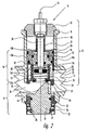
- FIG. 2 In fig. 2 is shown an embodiment of the valve according to the invention, said embodiment comprising a housing 9 which contains a combination of a differential pressure valve 10, an adjustable pre-setting 11 and a thermostat valve 12.
- the differential pressure valve 10 comprises a first, cup-shaped bush 14 which is placed in a bore 16 which is coaxial with the axis 15 of the housing 9.
- the first cup-shaped bush is connected with a second cup-shaped bush 14a which is arranged in such a manner that the bottoms in the two bushes face away from each other.
- the bottom in the second cup-shaped bush 14a forms a transverse wall 24 in the valve 8.
- a piston 13 which is stepped in diameter, of which the part with the smallest diameter lies inside the first cup-shaped bush 14, and the part with the largest diameter is inside the second cup-shaped bush 14a.
- the step between the two diameters hereby forms a first area 13a on the piston 13 in an annular space at the transition between the two cup-shaped bushes 14, 14a. That part of the piston 13 which is enclosed within the first cup-shaped bush 14 demarcates a space 26, where the area of the end surface of the piston 13 is indicated with the reference figure 13b in the drawing.
- a helical spring 25 is inserted between the bottom or the transverse wall 24 in the second cup-shaped bush 14a and the front of the piston 13.
- the spring 25 is secured in a centred manner on the front of the piston 13 by means of an annular recess or stepping-down, whereby radially outside the spring 25 said spring 25 demarcates a circular area indicated by the reference figure 13c, and also a circle with the area 13d inside the spring. From the front radially outside the spring 25, i.e. from the area 13c to the above-mentioned end surface 13b, the piston 13 also has a through-going bore 22.
- the housing 9 Transversely to the bore 16, the housing 9 has an inlet 20 and an outlet 21 for the medium, and along the circumference the second cup-shaped bush 14a is provided with a longitudinal channel 28 which extends from the inlet 20 to the above-mentioned circular space with the area 13a on the piston 13.
- the medium can also flow from the inlet 20 through an opening 27 with a seating 27a, which is configured in the bottom or the transverse wall 24 of the second cup-shaped bush 14a, and flow further into the space 29 enclosed within the windings of the spring 25.
- the area of the space 19 between the windings of the spring 25 changes in size depending on the length of the spring 25, in that the area is increased when the spring is extended and reduced when the spring 25 is compressed by the piston 13. If the spring is compressed completely together, so that the windings lie up against one another, the area can even be completely closed so that through-flow is prevented.
- the medium can flow out of the second cup-shaped bush 14a through an opening 23 which opens out in the outlet 21.
- the adjustable pre-setting 11 can be set to a desired through-flow opening by being turned around the axis 15, and can thereafter be locked in its setting. It can, for example, be configured as follows:
- a threaded bush 33 in which a cylindrical plug 34 is secured in a manner in which it cannot be displaced in the direction of the axis 15 of the housing 9, but can be turned around said axis.
- a bush-shaped setting element 35 At the free end of the threaded bush 33, there is also provided a bush-shaped setting element 35.
- the threaded bush 33 and the setting element 35 In a radial plane, the threaded bush 33 and the setting element 35 have cooperating teeth 36 which extend for a short distance axially. In a locking position for the setting element 35, the teeth 36 prevent a relative turning of the parts 33, 35, whereby the plug 34 is also prevented from turning.
- the plug 34 is configured with an inclined surface 39 which extends from the said end, in that the intersection between the end and the inclined surface 39 extends along a chord 40 on one side of the axis 15 of the plug, extends at an angle through the axis 15 of the plug and ends in a surface 41 which is at right angles to the axis 15.
- the inlet 20 has a predetermined area, and in the position of the plug 34 shown in fig. 2 there is unhindered flow through the inlet 20 and the opening 27 in the bottom or the transverse wall 24 of the second cup-shaped bush 14a.
- the plug 34 By turning the plug 34 at an angle of 180° around its axis in the threaded bush 33, and herewith in relation to the housing 9 and the inlet 20, the inlet 20 will be blocked. It will be clear that the turning of the plug 34 at angles of less than 180° from the shown position will block smaller or greater parts of the inlet 20, hereby making it possible to select a desired area of flow through the inlet 20 and to the opening 27.
- the thermostat valve 12 is of commonly known construction. Its arrangement comprises a spindle 30 which is surrounded by a helical spring 31 which with its one end abuts against a locking element 32 in the housing 9, and with its other end against the bottom of the first cup-shaped bush 14 in the housing. Outside the housing 9, the spindle 30 is connected to a not-shown thermostat bellows which can displace the spindle 30 in its longitudinal direction depending on the surrounding temperature and against the pressure from the spring 31.
- the spindle 30 also has the above-mentioned seal 42 which can close the opening 27 with the seating 27a in the bottom or the transverse wall 24 of the second cup-shaped bush 14a, regardless of the setting of the differential pressure valve 10 and the adjustable pre-setting 11.
Landscapes
- Engineering & Computer Science (AREA)
- Physics & Mathematics (AREA)
- General Engineering & Computer Science (AREA)
- Chemical & Material Sciences (AREA)
- Combustion & Propulsion (AREA)
- Mechanical Engineering (AREA)
- Thermal Sciences (AREA)
- General Physics & Mathematics (AREA)
- Automation & Control Theory (AREA)
- Fluid Mechanics (AREA)
- Temperature-Responsive Valves (AREA)
- Details Of Valves (AREA)
- Central Heating Systems (AREA)
- Steam Or Hot-Water Central Heating Systems (AREA)
- Lift Valve (AREA)
Claims (8)
- Vanne pour un système ayant un milieu caloporteur- qui circule à travers une pluralité d'échangeurs de chaleur (5) dans le système, incluant une soupape thermostatique (12) avec un boîtier (9) comportant une entrée (20) et une sortie (21), une tige (30) qui peut être déplacée par un soufflet thermostatique et porte un obturateur (42) et qui peut, en fonction de la dilatation / contraction du soufflet thermostatique et contre la pression d'un ressort (31) entourant la tige (30), respectivement fermer et ouvrir un orifice (27) pourvu d'un siège (27a) dans une paroi transversale (24) du boîtier (9) entre l'entrée (20) et la sortie (21), la dite vanne incluant en outre un dispositif de préréglage ajustable, la soupape thermostatique (12) étant agencée de manière à pouvoir interrompre l'écoulement entre l'entrée (20) et la sortie (21) indépendamment du dispositif de préréglage ajustable (11), caractérisée en ce que la vanne (8) comprend également un piston commandé par pression différentielle (13) pour la régulation de la pression différentielle du milieu caloporteur à travers le dispositif de préréglage ajustable (11) et la soupape thermostatique (12), la dite soupape thermostatique étant constituée par le siège (27a) et l'obturateur (42) et étant située entre l'entrée (20) et le piston (13).
- Vanne selon la revendication 1, caractérisée en ce que le piston (13) de la soupape à pression différentielle (10) est entouré par un premier manchon en forme de tasse (14) et est relié par l'intermédiaire de celui-ci à un deuxième manchon en forme de tasse (14a), les fonds des dits manchons étant tournés dans des directions opposées et étant disposés dans un alésage (16), qui est coaxial à l'axe (15) du boîtier (9), en ce que le piston (13) est épaulé en diamètre, de sorte que la partie de plus petit diamètre se trouve dans le premier manchon en forme de tasse (14), et en ce qu'un canal (22) conduit de l'avant du piston (13) à l'arrière du dit piston (13).
- Vanne selon la revendication 2, caractérisée en ce qu'un ressort (25) est prévu entre le piston (13) et le fond ou la paroi transversale (24) du deuxième manchon en forme de tasse (14a) d'une manière telle que la grandeur de l'espace (19) entre les spires du ressort (25) peut varier en fonction du mouvement du piston (13), le dit fond ou la paroi transversale (24) présentant le dit orifice (27) qui est délimité par le siège (27a).
- Vanne selon la revendication 3, caractérisée en ce que le deuxième manchon en forme de tasse (14a) présente, sur son côté extérieur, au moins un canal longitudinal (28) qui conduit de l'entrée (20) à un espace annulaire entre les deux manchons (14, 14a), une surface (13a) étant définie dans cet espace à l'endroit de l'épaulement du piston (13), en ce que, à l'intérieur du premier manchon en forme de tasse (14), l'arrière du piston présente une surface (13b), et en ce que le ressort (25), à l'endroit de sa butée contre le piston (13) à l'intérieur du deuxième manchon en forme de tasse (14a), délimite une surface (13c) sur son côté extérieur et une surface (13d) sur son côté intérieur.
- Vanne selon la revendication 1, caractérisée en ce que le dispositif de préréglage ajustable (11) comprend un bouchon cylindrique (34) qui est fixé par un manchon taraudé (33) d'une manière tournante mais verrouillable dans le boîtier (9), en ce que le bouchon (34) s'applique par l'extrémité située à l'intérieur du boîtier (9) contre le fond ou la paroi transversale (24) du deuxième manchon en forme de tasse (14a) et il est configuré de manière à présenter une surface inclinée qui part d'une corde (40) sur un côté de l'axe (15) du bouchon (34), s'étend de façon inclinée au-delà de l'axe (15) et au-delà de l'entrée (20), et se termine dans une surface (41) qui est perpendiculaire à l'axe (15).
- Vanne selon la revendication 5, caractérisée en ce que le manchon taraudé (33) est entouré par un élément de réglage (35), en ce que, dans un plan radial sur le manchon taraudé (33) et l'élément de réglage (35), il est prévu des dents coopérantes (36) de petite longueur axiale qui empêchent, dans une position de verrouillage de l'élément de réglage (35), une rotation relative entre le manchon taraudé (33) et l'élément de réglage (35), et en ce que le bouchon (34) et l'élément de réglage (35) dans un deuxième plan radial comportent des dents coopérantes (38), les dents (38) sur le bouchon (33) ayant une longueur axiale prédéterminée, de sorte que l'élément de réglage (35) dans une deuxième position reculée de la position de verrouillage peut faire tourner le bouchon (33) dans le corps (9).
- Vanne selon la revendication 6, caractérisée en ce que l'élément de réglage est maintenu dans la position verrouillée par un ressort (37) qui est inséré entre une collerette du bouchon (33) et une surface de contact sur l'élément de réglage (35).
- Vanne selon la revendication 1, caractérisée en ce que la soupape thermostatique (12) comprend une tige (30) qui s'étend à travers le premier manchon en forme de tasse (14) et le piston (13), en ce que la tige est entourée par un ressort (31) qui est comprimé entre un élément de blocage (32) et le fond du premier manchon en forme de tasse (14), et en ce que la tige (30), à l'extrémité qui fait saillie dans l'espace entouré par le ressort (25), porte le dit obturateur (42) qui est agencé de manière à s'appliquer contre le siège (27a) et à fermer l'orifice (27).
Applications Claiming Priority (4)
| Application Number | Priority Date | Filing Date | Title |
|---|---|---|---|
| DK109894 | 1994-09-23 | ||
| DK109894A DK171356B1 (da) | 1994-09-23 | 1994-09-23 | Ventil til et anlæg med et varmebærende medie |
| DK1098/94 | 1994-09-23 | ||
| PCT/DK1995/000373 WO1996009484A1 (fr) | 1994-09-23 | 1995-09-19 | Vanne pour systeme a milieu caloporteur |
Publications (4)
| Publication Number | Publication Date |
|---|---|
| EP0783642A1 EP0783642A1 (fr) | 1997-07-16 |
| EP0783642B1 EP0783642B1 (fr) | 2005-07-20 |
| EP0783642B8 EP0783642B8 (fr) | 2005-09-14 |
| EP0783642B9 true EP0783642B9 (fr) | 2006-01-18 |
Family
ID=8100969
Family Applications (1)
| Application Number | Title | Priority Date | Filing Date |
|---|---|---|---|
| EP95930415A Expired - Lifetime EP0783642B9 (fr) | 1994-09-23 | 1995-09-19 | Vanne pour systeme a milieu caloporteur |
Country Status (6)
| Country | Link |
|---|---|
| EP (1) | EP0783642B9 (fr) |
| AT (1) | ATE300007T1 (fr) |
| AU (1) | AU3381295A (fr) |
| DE (1) | DE69534320T2 (fr) |
| DK (1) | DK171356B1 (fr) |
| WO (1) | WO1996009484A1 (fr) |
Cited By (1)
| Publication number | Priority date | Publication date | Assignee | Title |
|---|---|---|---|---|
| EP4086492A4 (fr) * | 2020-01-02 | 2023-10-04 | Siemens Schweiz AG | Vanne de commande |
Families Citing this family (4)
| Publication number | Priority date | Publication date | Assignee | Title |
|---|---|---|---|---|
| DE10007291A1 (de) * | 2000-02-17 | 2001-08-23 | Nass Magnet Gmbh | Druckreduzierventil |
| DK176350B2 (da) | 2005-06-23 | 2008-10-13 | Frese As | Reguleringsventil |
| EP3418847B1 (fr) | 2016-03-24 | 2022-01-26 | Honeywell Technologies Sarl | Soupape de régulation de flux |
| IT202200002963A1 (it) * | 2022-02-17 | 2023-08-17 | Ivar Spa | Cartuccia di riduzione dinamica della pressione di un fluido e relativo dispositivo di trattamento di un fluido |
Family Cites Families (2)
| Publication number | Priority date | Publication date | Assignee | Title |
|---|---|---|---|---|
| DE2615895C2 (de) * | 1976-04-10 | 1988-09-08 | F.W. Oventrop Arn. Sohn Kg, 5787 Olsberg | Thermostatisch gesteuertes Regulierventil |
| DK160648B (da) * | 1988-08-05 | 1991-04-02 | Frese Armatur | Fremgangsmaade til regulering af et central- eller fjernvarmeanlaeg med en differenstrykventil og anlaeg til brug hertil |
-
1994
- 1994-09-23 DK DK109894A patent/DK171356B1/da not_active IP Right Cessation
-
1995
- 1995-09-19 EP EP95930415A patent/EP0783642B9/fr not_active Expired - Lifetime
- 1995-09-19 DE DE69534320T patent/DE69534320T2/de not_active Expired - Fee Related
- 1995-09-19 AU AU33812/95A patent/AU3381295A/en not_active Abandoned
- 1995-09-19 WO PCT/DK1995/000373 patent/WO1996009484A1/fr active IP Right Grant
- 1995-09-19 AT AT95930415T patent/ATE300007T1/de not_active IP Right Cessation
Cited By (1)
| Publication number | Priority date | Publication date | Assignee | Title |
|---|---|---|---|---|
| EP4086492A4 (fr) * | 2020-01-02 | 2023-10-04 | Siemens Schweiz AG | Vanne de commande |
Also Published As
| Publication number | Publication date |
|---|---|
| DE69534320D1 (de) | 2005-08-25 |
| DK109894A (da) | 1996-03-24 |
| DE69534320T2 (de) | 2006-04-20 |
| EP0783642B1 (fr) | 2005-07-20 |
| ATE300007T1 (de) | 2005-08-15 |
| EP0783642B8 (fr) | 2005-09-14 |
| EP0783642A1 (fr) | 1997-07-16 |
| AU3381295A (en) | 1996-04-09 |
| DK171356B1 (da) | 1996-09-16 |
| WO1996009484A1 (fr) | 1996-03-28 |
Similar Documents
| Publication | Publication Date | Title |
|---|---|---|
| EP0783643B1 (fr) | Vanne pour systeme a milieu caloporteur | |
| US5178324A (en) | Method of regulating a central or district heating plant by means of a differential pressure valve, and unit for working method | |
| US7744007B2 (en) | Thermostatic mixing valves and systems | |
| US5261597A (en) | Temperature responsive 3-way line valve with shape memory alloy actuator | |
| US5819785A (en) | Instantaneous hot water control device | |
| US6508406B1 (en) | Fail-safe proportional mixing valve | |
| US20010030309A1 (en) | Control valve with modified characteristics | |
| GB2217816A (en) | Temperature-responsive valves | |
| US20020084068A1 (en) | Three-way heating system valve with heat exchanger pressure regulation | |
| EP0568122B1 (fr) | Arrangement de soupape prévu pour installations de chauffage ainsi que pour chauffe-eau domestique | |
| EP0783642B9 (fr) | Vanne pour systeme a milieu caloporteur | |
| US5931375A (en) | Valve for a system having an energy-carrying medium | |
| US4653524A (en) | Control valve assembly | |
| EP0742876A1 (fr) | Robinet de radiateur | |
| EP3669106B1 (fr) | Soupape de commande pour système de chauffage et/ou de refroidissement | |
| WO1990004141A1 (fr) | Dispositif a vanne d'arret et clapet antiretour combines pour chauffe-eau du type a compresseur | |
| US3901438A (en) | Thermostat-regulated radiator valve for single or double conduit central heating systems | |
| WO1991005968A1 (fr) | Soupape melangeuse | |
| EP0314661A2 (fr) | Appareil avec combinaison de vanne d'arrêt et anti-retour pour un chauffe-eau sous pression | |
| RU2784132C1 (ru) | Клапан балансировочный | |
| US3327944A (en) | Automatic balance valve | |
| EP0839304B1 (fr) | Distributeur pour une installation de chauffage ou de refrigeration | |
| LT3124B (en) | Regulator | |
| AU4754602A (en) | Fail-safe proportional mixing valve | |
| GB2041167A (en) | Valves |
Legal Events
| Date | Code | Title | Description |
|---|---|---|---|
| PUAI | Public reference made under article 153(3) epc to a published international application that has entered the european phase |
Free format text: ORIGINAL CODE: 0009012 |
|
| 17P | Request for examination filed |
Effective date: 19970423 |
|
| AK | Designated contracting states |
Kind code of ref document: A1 Designated state(s): AT BE CH DE DK ES FR GB GR IE IT LI NL PT SE |
|
| 17Q | First examination report despatched |
Effective date: 19990520 |
|
| GRAG | Despatch of communication of intention to grant |
Free format text: ORIGINAL CODE: EPIDOS AGRA |
|
| GRAG | Despatch of communication of intention to grant |
Free format text: ORIGINAL CODE: EPIDOS AGRA |
|
| GRAH | Despatch of communication of intention to grant a patent |
Free format text: ORIGINAL CODE: EPIDOS IGRA |
|
| RAP1 | Party data changed (applicant data changed or rights of an application transferred) |
Owner name: FRESE ARMATUR A/S |
|
| GRAH | Despatch of communication of intention to grant a patent |
Free format text: ORIGINAL CODE: EPIDOS IGRA |
|
| 19A | Proceedings stayed before grant |
Effective date: 20010323 |
|
| 19F | Resumption of proceedings before grant (after stay of proceedings) |
Effective date: 20050301 |
|
| GRAA | (expected) grant |
Free format text: ORIGINAL CODE: 0009210 |
|
| AK | Designated contracting states |
Kind code of ref document: B1 Designated state(s): AT BE CH DE DK ES FR GB GR IE IT LI NL PT SE |
|
| PG25 | Lapsed in a contracting state [announced via postgrant information from national office to epo] |
Ref country code: NL Free format text: LAPSE BECAUSE OF FAILURE TO SUBMIT A TRANSLATION OF THE DESCRIPTION OR TO PAY THE FEE WITHIN THE PRESCRIBED TIME-LIMIT Effective date: 20050720 Ref country code: LI Free format text: LAPSE BECAUSE OF FAILURE TO SUBMIT A TRANSLATION OF THE DESCRIPTION OR TO PAY THE FEE WITHIN THE PRESCRIBED TIME-LIMIT Effective date: 20050720 Ref country code: IT Free format text: LAPSE BECAUSE OF FAILURE TO SUBMIT A TRANSLATION OF THE DESCRIPTION OR TO PAY THE FEE WITHIN THE PRESCRIBED TIME-LIMIT;WARNING: LAPSES OF ITALIAN PATENTS WITH EFFECTIVE DATE BEFORE 2007 MAY HAVE OCCURRED AT ANY TIME BEFORE 2007. THE CORRECT EFFECTIVE DATE MAY BE DIFFERENT FROM THE ONE RECORDED. Effective date: 20050720 Ref country code: CH Free format text: LAPSE BECAUSE OF FAILURE TO SUBMIT A TRANSLATION OF THE DESCRIPTION OR TO PAY THE FEE WITHIN THE PRESCRIBED TIME-LIMIT Effective date: 20050720 Ref country code: BE Free format text: LAPSE BECAUSE OF FAILURE TO SUBMIT A TRANSLATION OF THE DESCRIPTION OR TO PAY THE FEE WITHIN THE PRESCRIBED TIME-LIMIT Effective date: 20050720 Ref country code: AT Free format text: LAPSE BECAUSE OF FAILURE TO SUBMIT A TRANSLATION OF THE DESCRIPTION OR TO PAY THE FEE WITHIN THE PRESCRIBED TIME-LIMIT Effective date: 20050720 |
|
| REG | Reference to a national code |
Ref country code: GB Ref legal event code: FG4D |
|
| REG | Reference to a national code |
Ref country code: CH Ref legal event code: EP |
|
| RAP2 | Party data changed (patent owner data changed or rights of a patent transferred) |
Owner name: FRESE A/S |
|
| REG | Reference to a national code |
Ref country code: IE Ref legal event code: FG4D |
|
| REF | Corresponds to: |
Ref document number: 69534320 Country of ref document: DE Date of ref document: 20050825 Kind code of ref document: P |
|
| PG25 | Lapsed in a contracting state [announced via postgrant information from national office to epo] |
Ref country code: IE Free format text: LAPSE BECAUSE OF NON-PAYMENT OF DUE FEES Effective date: 20050919 |
|
| NLT2 | Nl: modifications (of names), taken from the european patent patent bulletin |
Owner name: FRESE A/S Effective date: 20050817 |
|
| PG25 | Lapsed in a contracting state [announced via postgrant information from national office to epo] |
Ref country code: SE Free format text: LAPSE BECAUSE OF FAILURE TO SUBMIT A TRANSLATION OF THE DESCRIPTION OR TO PAY THE FEE WITHIN THE PRESCRIBED TIME-LIMIT Effective date: 20051020 Ref country code: GR Free format text: LAPSE BECAUSE OF FAILURE TO SUBMIT A TRANSLATION OF THE DESCRIPTION OR TO PAY THE FEE WITHIN THE PRESCRIBED TIME-LIMIT Effective date: 20051020 Ref country code: DK Free format text: LAPSE BECAUSE OF FAILURE TO SUBMIT A TRANSLATION OF THE DESCRIPTION OR TO PAY THE FEE WITHIN THE PRESCRIBED TIME-LIMIT Effective date: 20051020 |
|
| PGFP | Annual fee paid to national office [announced via postgrant information from national office to epo] |
Ref country code: GB Payment date: 20051020 Year of fee payment: 11 |
|
| PGFP | Annual fee paid to national office [announced via postgrant information from national office to epo] |
Ref country code: DE Payment date: 20051027 Year of fee payment: 11 |
|
| PGFP | Annual fee paid to national office [announced via postgrant information from national office to epo] |
Ref country code: FR Payment date: 20051028 Year of fee payment: 11 |
|
| PG25 | Lapsed in a contracting state [announced via postgrant information from national office to epo] |
Ref country code: ES Free format text: LAPSE BECAUSE OF FAILURE TO SUBMIT A TRANSLATION OF THE DESCRIPTION OR TO PAY THE FEE WITHIN THE PRESCRIBED TIME-LIMIT Effective date: 20051031 |
|
| PG25 | Lapsed in a contracting state [announced via postgrant information from national office to epo] |
Ref country code: PT Free format text: LAPSE BECAUSE OF FAILURE TO SUBMIT A TRANSLATION OF THE DESCRIPTION OR TO PAY THE FEE WITHIN THE PRESCRIBED TIME-LIMIT Effective date: 20051221 |
|
| REG | Reference to a national code |
Ref country code: CH Ref legal event code: PL |
|
| NLV1 | Nl: lapsed or annulled due to failure to fulfill the requirements of art. 29p and 29m of the patents act | ||
| ET | Fr: translation filed | ||
| PLBE | No opposition filed within time limit |
Free format text: ORIGINAL CODE: 0009261 |
|
| STAA | Information on the status of an ep patent application or granted ep patent |
Free format text: STATUS: NO OPPOSITION FILED WITHIN TIME LIMIT |
|
| REG | Reference to a national code |
Ref country code: IE Ref legal event code: MM4A |
|
| 26N | No opposition filed |
Effective date: 20060421 |
|
| PG25 | Lapsed in a contracting state [announced via postgrant information from national office to epo] |
Ref country code: DE Free format text: LAPSE BECAUSE OF NON-PAYMENT OF DUE FEES Effective date: 20070403 |
|
| GBPC | Gb: european patent ceased through non-payment of renewal fee |
Effective date: 20060919 |
|
| REG | Reference to a national code |
Ref country code: FR Ref legal event code: ST Effective date: 20070531 |
|
| PG25 | Lapsed in a contracting state [announced via postgrant information from national office to epo] |
Ref country code: GB Free format text: LAPSE BECAUSE OF NON-PAYMENT OF DUE FEES Effective date: 20060919 |
|
| PG25 | Lapsed in a contracting state [announced via postgrant information from national office to epo] |
Ref country code: FR Free format text: LAPSE BECAUSE OF NON-PAYMENT OF DUE FEES Effective date: 20061002 |