EP0783450B1 - Method and apparatus for packaging compressible insulation material - Google Patents
Method and apparatus for packaging compressible insulation material Download PDFInfo
- Publication number
- EP0783450B1 EP0783450B1 EP95932530A EP95932530A EP0783450B1 EP 0783450 B1 EP0783450 B1 EP 0783450B1 EP 95932530 A EP95932530 A EP 95932530A EP 95932530 A EP95932530 A EP 95932530A EP 0783450 B1 EP0783450 B1 EP 0783450B1
- Authority
- EP
- European Patent Office
- Prior art keywords
- roll
- insulation material
- belt
- mandrel
- insulation
- Prior art date
- Legal status (The legal status is an assumption and is not a legal conclusion. Google has not performed a legal analysis and makes no representation as to the accuracy of the status listed.)
- Expired - Lifetime
Links
- 239000012774 insulation material Substances 0.000 title claims abstract description 54
- 238000000034 method Methods 0.000 title claims abstract description 21
- 238000004806 packaging method and process Methods 0.000 title claims abstract description 16
- 238000009413 insulation Methods 0.000 claims abstract description 40
- 238000005096 rolling process Methods 0.000 claims abstract description 12
- 238000003825 pressing Methods 0.000 claims abstract description 3
- 238000007664 blowing Methods 0.000 claims 1
- 238000012856 packing Methods 0.000 claims 1
- 238000011144 upstream manufacturing Methods 0.000 claims 1
- 239000000463 material Substances 0.000 description 8
- 230000006835 compression Effects 0.000 description 7
- 238000007906 compression Methods 0.000 description 7
- 239000011152 fibreglass Substances 0.000 description 4
- 230000002950 deficient Effects 0.000 description 2
- 238000004804 winding Methods 0.000 description 2
- 230000001154 acute effect Effects 0.000 description 1
- 230000001413 cellular effect Effects 0.000 description 1
- 230000007547 defect Effects 0.000 description 1
- 239000000835 fiber Substances 0.000 description 1
- 239000002657 fibrous material Substances 0.000 description 1
- 239000006260 foam Substances 0.000 description 1
- 239000003365 glass fiber Substances 0.000 description 1
- 238000005461 lubrication Methods 0.000 description 1
- 238000004519 manufacturing process Methods 0.000 description 1
- 239000011159 matrix material Substances 0.000 description 1
- 239000011490 mineral wool Substances 0.000 description 1
- 239000005022 packaging material Substances 0.000 description 1
- 238000012858 packaging process Methods 0.000 description 1
- 229920000642 polymer Polymers 0.000 description 1
- 230000005855 radiation Effects 0.000 description 1
- 239000007787 solid Substances 0.000 description 1
- 238000003860 storage Methods 0.000 description 1
Images


Classifications
-
- B—PERFORMING OPERATIONS; TRANSPORTING
- B65—CONVEYING; PACKING; STORING; HANDLING THIN OR FILAMENTARY MATERIAL
- B65H—HANDLING THIN OR FILAMENTARY MATERIAL, e.g. SHEETS, WEBS, CABLES
- B65H18/00—Winding webs
- B65H18/08—Web-winding mechanisms
- B65H18/14—Mechanisms in which power is applied to web roll, e.g. to effect continuous advancement of web
- B65H18/22—Mechanisms in which power is applied to web roll, e.g. to effect continuous advancement of web by friction band
-
- B—PERFORMING OPERATIONS; TRANSPORTING
- B65—CONVEYING; PACKING; STORING; HANDLING THIN OR FILAMENTARY MATERIAL
- B65H—HANDLING THIN OR FILAMENTARY MATERIAL, e.g. SHEETS, WEBS, CABLES
- B65H18/00—Winding webs
- B65H18/08—Web-winding mechanisms
- B65H18/10—Mechanisms in which power is applied to web-roll spindle
-
- B—PERFORMING OPERATIONS; TRANSPORTING
- B65—CONVEYING; PACKING; STORING; HANDLING THIN OR FILAMENTARY MATERIAL
- B65H—HANDLING THIN OR FILAMENTARY MATERIAL, e.g. SHEETS, WEBS, CABLES
- B65H2511/00—Dimensions; Position; Numbers; Identification; Occurrences
- B65H2511/10—Size; Dimensions
- B65H2511/14—Diameter, e.g. of roll or package
-
- B—PERFORMING OPERATIONS; TRANSPORTING
- B65—CONVEYING; PACKING; STORING; HANDLING THIN OR FILAMENTARY MATERIAL
- B65H—HANDLING THIN OR FILAMENTARY MATERIAL, e.g. SHEETS, WEBS, CABLES
- B65H2515/00—Physical entities not provided for in groups B65H2511/00 or B65H2513/00
- B65H2515/30—Forces; Stresses
- B65H2515/31—Tensile forces
-
- B—PERFORMING OPERATIONS; TRANSPORTING
- B65—CONVEYING; PACKING; STORING; HANDLING THIN OR FILAMENTARY MATERIAL
- B65H—HANDLING THIN OR FILAMENTARY MATERIAL, e.g. SHEETS, WEBS, CABLES
- B65H2515/00—Physical entities not provided for in groups B65H2511/00 or B65H2513/00
- B65H2515/30—Forces; Stresses
- B65H2515/34—Pressure, e.g. fluid pressure
-
- B—PERFORMING OPERATIONS; TRANSPORTING
- B65—CONVEYING; PACKING; STORING; HANDLING THIN OR FILAMENTARY MATERIAL
- B65H—HANDLING THIN OR FILAMENTARY MATERIAL, e.g. SHEETS, WEBS, CABLES
- B65H2701/00—Handled material; Storage means
- B65H2701/10—Handled articles or webs
- B65H2701/17—Nature of material
- B65H2701/177—Fibrous or compressible material
-
- B—PERFORMING OPERATIONS; TRANSPORTING
- B65—CONVEYING; PACKING; STORING; HANDLING THIN OR FILAMENTARY MATERIAL
- B65H—HANDLING THIN OR FILAMENTARY MATERIAL, e.g. SHEETS, WEBS, CABLES
- B65H2701/00—Handled material; Storage means
- B65H2701/10—Handled articles or webs
- B65H2701/18—Form of handled article or web
- B65H2701/184—Wound packages
- B65H2701/1846—Parts concerned
-
- B—PERFORMING OPERATIONS; TRANSPORTING
- B65—CONVEYING; PACKING; STORING; HANDLING THIN OR FILAMENTARY MATERIAL
- B65H—HANDLING THIN OR FILAMENTARY MATERIAL, e.g. SHEETS, WEBS, CABLES
- B65H2701/00—Handled material; Storage means
- B65H2701/10—Handled articles or webs
- B65H2701/19—Specific article or web
- B65H2701/1922—Specific article or web for covering surfaces such as carpets, roads, roofs or walls
Definitions
- This invention relates to packaging compressible insulation material for shipping and storage. More particularly, this invention relates to rolling up compressible insulation material to a highly compressed condition for efficient shipping and storing.
- Insulation products are usually comprised of a fibrous or cellular matrix which inhibits heat transfer by solid conduction and radiation, and also provides or defines cells or voids to limit convective heat transfer. Accordingly, these products necessarily contain a high percentage of air. In order to efficiently transport and store the insulation products from the manufacturing site to the ultimate destination, it is desirable to significantly compress the insulation material. Care must be taken not to overcompress the insulation because that would lead to loss of the ability to recover the thickness needed for insulation value when the packaging is removed. Fiberglass insulation products are typically packaged either as flat or folded batts in bags, or as rolls of long insulation blankets.
- Existing glass fiber insulation packaging machines for rolling up fibrous insulation products into rolls are of two general types.
- the first employs a mandrel to which the leading edge of the insulation blanket is attached for rolling up. These machines are somewhat deficient in that they typically overcompress the leading portion of the blanket, resulting in loss of insulation value.
- the other machine for insulation rolls is the belt roll-up machine, which uses a belt which is wrapped around the insulation roll as it is being rolled up.
- the belt roll-up has a series of rollers defining the path of the belt, and allowing the loop of the belt to expand to accommodate the growing roll during the packaging process.
- the belt roll-up is deficient in that it is difficult to accurately control the compressive forces applied to the insulation material during roll-up, resulting in improperly compressed rolls of insulation, i.e., overcompressed or undercompressed. Further, both the belt roll-up and the mandrel machines are limited in the amount of compression, and hence the density, in the ultimate rolled insulation package.
- WO-A-94/12417 describes a method and apparatus for forming spiral wound rolls from strips of compressible material comprising a system of belt conveyors.
- a first endless belt conveyor delivers the strips of compressible material into a winding space which is defined by the first belt conveyor and an inclined second endless belt conveyor, a compression roll and a third endless belt conveyor.
- the first endless belt conveyor delivers the compressible material it contacts the inclined second conveyor which is set at an acute angle to the first conveyor - this contact turns the compressible material back on itself to form the spiral roll.
- the first coils of the spiral roll are formed the compressible material is maintained in tension and compression by contact a compression roll.
- the third conveyor which is positioned between the compression roll and the first conveyor. This third conveyor can be moved to generate a larger winding space as the roll increases in diameter.
- the invention provides for an insulation roll-up machine which overcomes the defects of conventional machines by applying a generally constant compressive force during the roll up of the insulation material.
- the insulation material is rolled up on a mandrel and is contacted by a traveling belt, and preferably a pair of opposed belts, the tension of which is increased during the rolling up process.
- method of packaging compressible insulation material comprising feeding insulation material into contact with a mandrel, rolling up the insulation material on the mandrel to form an insulation roll, applying pressure on the insulation material, during the rolling of the insulation material, with a traveling belt which is adapted to contact the roll being formed with an increasing area of contact as the diameter of the roll increases, and increasing tension on the belt as the diameter of the roll increases in order to maintain a substantially constant pressure on the insulation material.
- a traveling belt which is adapted to contact the roll being formed with an increasing area of contact as the diameter of the roll increases, and increasing tension on the belt as the diameter of the roll increases in order to maintain a substantially constant pressure on the insulation material.
- there are two opposed belts the tension of which is increased to maintain a substantially constant pressure on the insulation material.
- the use of two opposed belts helps drive the insulation into a roll around the mandrel, while controlling the pressure on the roll.
- the insulation roll will be highly compressed without overcompressing the leading portion of the insulation blanket. It is desirable to provide a constant pressure or hoop stress on the insulation material as the roll grows in size.
- the tension in the belt in a fashion roughly proportional to the diameter of the roll, the hoop stress can be maintained substantially constant.
- the belts are mounted for travel around at least three rollers, and the tension in the belts is controlled by the movement of at least one of the rollers. Controlled movement of the moveable roller changes the path of the belts, thereby modifying the tension in the belts.
- the pressure applied to the insulation material by the belts is proportional to the tension in the belts.
- the tension is increased from an initial tension to a final tension, the final tension being within the range of from about 1.2 to about 2.0 times the initial tension as the diameter of the roll increases.
- the final tension is about 1.7 times the initial tension.
- the belts are engaged by deflector rollers to increase the angle of wrap of the belt around the insulation material.
- the deflector rollers change the path of the belts so that they are forced to travel a longer distance around the circumference of the roll being formed on the mandrel.
- the deflector roller is engaged with the belt for less than one-half of the length of the time period during which the insulation material is being rolled up. After this time the roll has reached a size for the angle of wrap to be sufficient to enable the tension of the belt to control the pressure on the roll being formed on the mandrel.
- the step of engaging the deflector roller is carried out during the first 1/2 of the packaging cycle. Most preferably, the step of engaging the deflector roller is carried out during the first 1/3 of the packaging cycle.
- apparatus for packaging compressible insulation material comprising a mandrel mounted for rotation, and adapted to roll up insulation material into a roll a belt adapted to contact the roll being formed on the mandrel to apply pressure to the roll, the belt being positioned so that it contacts the roll being formed with an increasing area of contact as the diameter of the roll increases, and means for increasing tension on the belt as the diameter of the roll increases in order to maintain a substantially constant pressure on the insulation material.
- the invention will be described in terms of packaging fiberglass insulation material. It is to be understood that the method and apparatus of the invention can be used to package insulation material of other fibrous material, such as rockwool fibers or polymers, or other nonfibrous insulation material such as compressible foams.
- the insulation material most suitable for use with the invention is light density fiberglass building insulation having a, density within the range of from about 4.806 to 11 213 kg/m 3 (0.3 to 0.7 pounds per cubic foot).
- the invention can be employed using rolls of rolled up batts, as well as rolls of a continuous insulation blanket.
- insulation material such as fiberglass blanket 10
- precompression conveyors 12 can be gradually converging to slowly evacuate the air from the blanket.
- the primary apparatus for rolling up the blanket is rotatably mounted mandrel 14 and opposed belts 16 and 18.
- the upper and lower belts are mounted to travel in opposite directions as they contact the insulation blanket, and to press on the insulation blanket to assure that the roll has proper compression.
- the upper belt is mounted for travel around three upper belt rollers 20, 22, and 24, respectively, while the lower belt is mounted for travel around three lower belt rollers, 30, 32, and 34, respectively.
- Upper belt roller 24 is mounted for vertical movement and can be moved vertically by the action of any suitable means, such as pneumatic apparatus 36. It is to be understood that numerous other orientations or methods can be employed to control tension in the belts.
- lower belt roller 34 can be adapted to be moved vertically downward by pneumatic cylinder 38.
- the belts can be of any type suitable for continuously applying force and direction to the insulation material, such as wire mesh, canvas, and perforated rubber belts.
- the upper and lower belt rollers are mounted for movement to accommodate changes in the path of the belt, and the amount of resistance to the force applied to the upper and lower rollers is controlled by the positioning of the upper and lower rollers by pneumatic cylinders 36 and 38. The amount of resistance to movement controls the tension, and hence the pressure on the insulation material being rolled up.
- upper and lower deflector rollers 40 and 42 are mounted for movement into and out of contact with the belts, and are adapted with means, such as pneumatic cylinders 44 and 46, respectively, for moving them into engagement with the belts.
- engagement of upper deflector roller 40 causes the upper belt to deviate from the straight path between upper belt rollers 20 and 22.
- Engagement of the deflector rollers also increases the tension in the belts, and also applies additional pressure on the insulation blanket being rolled up.
- this deviation in the straight line path causes the upper belt to increase the angle of wrap around insulation roll 50 (shown in Figure 4) which is being rolled up on the mandrel.
- engagement of lower deflector roller 42 causes the lower belt to deviate from the straight path between lower belt rollers 30 and 32, and increase the angle of wrap around the insulation roll.
- the upper and lower deflector rollers can be retracted out of engagement with the belts, primarily because the angle of wrap of the belts is increased by virtue of the increase in size of the roll.
- the deflector rollers are engaged before the leading end of the insulation blanket is attached to the mandrel.
- the deflector rollers can be engaged during the entire packaging cycle, preferably the deflector rollers are disengaged alter about a quarter of the insulation blanket is wound up on the mandrel.
- the mandrel can be adapted with apertures or air ports 52 which can be operatively connected to a source of vacuum or air pressure, not shown, via conduit 54.
- the air ports are preferably connected to a source of negative gauge pressure to facilitate attachment of the beginning end of the insulation blanket to the mandrel.
- the startup phase of the process will be facilitated by rotatably driving the mandrel.
- the air ports can be connected to a source of positive gauge air pressure, not shown, to enable the roll to more easily be slid off or removed from the mandrel. It has been found that the insulation roll can be removed even without lubrication or the use of a core tube.
- Ejection of the roll from the mandrel is preferably accomplished by the movement of ejector ring 56 along the mandrel.
- the ejector ring can be operated by any means, such as pistons 58. It is to be understood that any means suitable for removing the completed roll from the mandrel can be used.
- the rolls can also be removed by hand.
- a wrapper or other suitable packaging or restraint material is applied to the roll before the pressure from the upper and lower belts is removed. By using two belts (the upper and the lower) the wrapper can be inserted and rolled up around the completed insulation roll while the insulation roll is still within the confines of the upper and lower belts.
- the upper and lower belts are mounted for disengagement from the mandrel and roll.
- the upper and lower belts are mounted for an open jaw type movement, as shown in Figure 6, to enable easy removal of the roll.
- a wrapper or other suitable packaging material is applied to the roll before the pressure from the upper and lower belts is removed.
- the invention can be carried out using just one belt and a backup device, such as backup roller 60.
- the backup roller provides a surface upon which the package can be pressed by the upper belt.
- the backup roller can be mounted for vertical movement to allow for increases in package size as the insulation material is being rolled up. Two or more backup rollers could also be employed.
- This invention will be found useful in packaging compressible materials of the type used for thermal and acoustical insulation.
Landscapes
- Containers And Plastic Fillers For Packaging (AREA)
- Wrapping Of Specific Fragile Articles (AREA)
- Basic Packing Technique (AREA)
- Auxiliary Devices For And Details Of Packaging Control (AREA)
- Winding Of Webs (AREA)
Abstract
Description
- This invention relates to packaging compressible insulation material for shipping and storage. More particularly, this invention relates to rolling up compressible insulation material to a highly compressed condition for efficient shipping and storing.
- Insulation products are usually comprised of a fibrous or cellular matrix which inhibits heat transfer by solid conduction and radiation, and also provides or defines cells or voids to limit convective heat transfer. Accordingly, these products necessarily contain a high percentage of air. In order to efficiently transport and store the insulation products from the manufacturing site to the ultimate destination, it is desirable to significantly compress the insulation material. Care must be taken not to overcompress the insulation because that would lead to loss of the ability to recover the thickness needed for insulation value when the packaging is removed. Fiberglass insulation products are typically packaged either as flat or folded batts in bags, or as rolls of long insulation blankets.
- Existing glass fiber insulation packaging machines for rolling up fibrous insulation products into rolls are of two general types. The first employs a mandrel to which the leading edge of the insulation blanket is attached for rolling up. These machines are somewhat deficient in that they typically overcompress the leading portion of the blanket, resulting in loss of insulation value. The other machine for insulation rolls is the belt roll-up machine, which uses a belt which is wrapped around the insulation roll as it is being rolled up. The belt roll-up has a series of rollers defining the path of the belt, and allowing the loop of the belt to expand to accommodate the growing roll during the packaging process. The belt roll-up is deficient in that it is difficult to accurately control the compressive forces applied to the insulation material during roll-up, resulting in improperly compressed rolls of insulation, i.e., overcompressed or undercompressed. Further, both the belt roll-up and the mandrel machines are limited in the amount of compression, and hence the density, in the ultimate rolled insulation package.
- WO-A-94/12417 describes a method and apparatus for forming spiral wound rolls from strips of compressible material comprising a system of belt conveyors. A first endless belt conveyor delivers the strips of compressible material into a winding space which is defined by the first belt conveyor and an inclined second endless belt conveyor, a compression roll and a third endless belt conveyor. As the first endless belt conveyor delivers the compressible material it contacts the inclined second conveyor which is set at an acute angle to the first conveyor - this contact turns the compressible material back on itself to form the spiral roll. When the first coils of the spiral roll are formed the compressible material is maintained in tension and compression by contact a compression roll. After a sufficient core of spiral wound roll is formed the compressible material is maintained in compression and tension by containing the third conveyor which is positioned between the compression roll and the first conveyor. This third conveyor can be moved to generate a larger winding space as the roll increases in diameter.
- The invention provides for an insulation roll-up machine which overcomes the defects of conventional machines by applying a generally constant compressive force during the roll up of the insulation material. The insulation material is rolled up on a mandrel and is contacted by a traveling belt, and preferably a pair of opposed belts, the tension of which is increased during the rolling up process.
- According to this invention, there is provided method of packaging compressible insulation material comprising feeding insulation material into contact with a mandrel, rolling up the insulation material on the mandrel to form an insulation roll, applying pressure on the insulation material, during the rolling of the insulation material, with a traveling belt which is adapted to contact the roll being formed with an increasing area of contact as the diameter of the roll increases, and increasing tension on the belt as the diameter of the roll increases in order to maintain a substantially constant pressure on the insulation material. Preferably, there are two opposed belts, the tension of which is increased to maintain a substantially constant pressure on the insulation material.
- The use of two opposed belts helps drive the insulation into a roll around the mandrel, while controlling the pressure on the roll. By increasing the tension on the belts as the diameter of the roll increases, the insulation roll will be highly compressed without overcompressing the leading portion of the insulation blanket. It is desirable to provide a constant pressure or hoop stress on the insulation material as the roll grows in size. By increasing the tension in the belt in a fashion roughly proportional to the diameter of the roll, the hoop stress can be maintained substantially constant.
- In a specific embodiment of the invention, the belts are mounted for travel around at least three rollers, and the tension in the belts is controlled by the movement of at least one of the rollers. Controlled movement of the moveable roller changes the path of the belts, thereby modifying the tension in the belts. Generally, the pressure applied to the insulation material by the belts is proportional to the tension in the belts. In a specific embodiment of the invention, the tension is increased from an initial tension to a final tension, the final tension being within the range of from about 1.2 to about 2.0 times the initial tension as the diameter of the roll increases. Preferably, the final tension is about 1.7 times the initial tension.
- In another embodiment of the invention, the belts are engaged by deflector rollers to increase the angle of wrap of the belt around the insulation material. The deflector rollers change the path of the belts so that they are forced to travel a longer distance around the circumference of the roll being formed on the mandrel. Preferably, the deflector roller is engaged with the belt for less than one-half of the length of the time period during which the insulation material is being rolled up. After this time the roll has reached a size for the angle of wrap to be sufficient to enable the tension of the belt to control the pressure on the roll being formed on the mandrel.
- In a preferred embodiment of the invention the step of engaging the deflector roller is carried out during the first 1/2 of the packaging cycle. Most preferably, the step of engaging the deflector roller is carried out during the first 1/3 of the packaging cycle.
- According to this invention, there is also provided apparatus for packaging compressible insulation material comprising a mandrel mounted for rotation, and adapted to roll up insulation material into a roll a belt adapted to contact the roll being formed on the mandrel to apply pressure to the roll, the belt being positioned so that it contacts the roll being formed with an increasing area of contact as the diameter of the roll increases, and means for increasing tension on the belt as the diameter of the roll increases in order to maintain a substantially constant pressure on the insulation material.
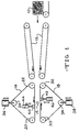
- Figure 1 is a schematic cross-sectional view in elevation of apparatus for packaging compressible insulation material according to the invention.
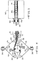
- Figure 2 is a schematic view in elevation of a portion of the apparatus of Figure 1, with the deflector roller engaged, prior to the beginning of the roll-up process.
- Figure 3 is a view similar to Figure 2, in which the insulation material is being rolled up.
- Figure 4 is a view similar to Figure 3, in which the roll is nearly completed.
- Figure 5 is a schematic view in elevation of the mandrel and ejector ring of the apparatus shown in Figure 1.
- Figure 6 is a view similar to Figure 4, in which the upper and lower belts have been removed from engagement with the completed roll to remove the roll from the mandrel.
- Figure 7 is a schematic view in elevation of an alternative apparatus having an upper belt and a lower nip roll for packaging compressible insulation material according to the invention.
-
- The invention will be described in terms of packaging fiberglass insulation material. It is to be understood that the method and apparatus of the invention can be used to package insulation material of other fibrous material, such as rockwool fibers or polymers, or other nonfibrous insulation material such as compressible foams. The insulation material most suitable for use with the invention is light density fiberglass building insulation having a, density within the range of from about 4.806 to 11 213 kg/m3 (0.3 to 0.7 pounds per cubic foot). The invention can be employed using rolls of rolled up batts, as well as rolls of a continuous insulation blanket.
- Referring to Figure 1, it can be seen that insulation material, such as
fiberglass blanket 10, can be introduced to the apparatus of the invention by means of any suitable conveyor system, such asprecompression conveyors 12. The precompression conveyors can be gradually converging to slowly evacuate the air from the blanket. - The primary apparatus for rolling up the blanket is rotatably mounted
mandrel 14 and opposedbelts upper belt rollers Upper belt roller 24 is mounted for vertical movement and can be moved vertically by the action of any suitable means, such aspneumatic apparatus 36. It is to be understood that numerous other orientations or methods can be employed to control tension in the belts. Similarly,lower belt roller 34 can be adapted to be moved vertically downward bypneumatic cylinder 38. The belts can be of any type suitable for continuously applying force and direction to the insulation material, such as wire mesh, canvas, and perforated rubber belts. - As the roll of insulation grows in size, the increased angle of wrap around the insulation roll increases the force applied to all the rollers, and therefore tends to increase the tension in the belt. The upper and lower belt rollers are mounted for movement to accommodate changes in the path of the belt, and the amount of resistance to the force applied to the upper and lower rollers is controlled by the positioning of the upper and lower rollers by
pneumatic cylinders - Mounted within the path of travel of the two belts are upper and
lower deflector rollers pneumatic cylinders upper deflector roller 40 causes the upper belt to deviate from the straight path betweenupper belt rollers lower deflector roller 42 causes the lower belt to deviate from the straight path betweenlower belt rollers - As shown in Figure 4, during the later stages of the roll-up process the upper and lower deflector rollers can be retracted out of engagement with the belts, primarily because the angle of wrap of the belts is increased by virtue of the increase in size of the roll. During the startup phase of the operation, the deflector rollers are engaged before the leading end of the insulation blanket is attached to the mandrel. Although the deflector rollers can be engaged during the entire packaging cycle, preferably the deflector rollers are disengaged alter about a quarter of the insulation blanket is wound up on the mandrel.
- As shown in Figure 5, the mandrel can be adapted with apertures or
air ports 52 which can be operatively connected to a source of vacuum or air pressure, not shown, viaconduit 54. During startup phase of the roll-up process, the air ports are preferably connected to a source of negative gauge pressure to facilitate attachment of the beginning end of the insulation blanket to the mandrel. The startup phase of the process will be facilitated by rotatably driving the mandrel. After the insulation blanket is completely rolled up, the air ports can be connected to a source of positive gauge air pressure, not shown, to enable the roll to more easily be slid off or removed from the mandrel. It has been found that the insulation roll can be removed even without lubrication or the use of a core tube. Ejection of the roll from the mandrel is preferably accomplished by the movement ofejector ring 56 along the mandrel. The ejector ring can be operated by any means, such aspistons 58. It is to be understood that any means suitable for removing the completed roll from the mandrel can be used. The rolls can also be removed by hand. Preferably, a wrapper or other suitable packaging or restraint material is applied to the roll before the pressure from the upper and lower belts is removed. By using two belts (the upper and the lower) the wrapper can be inserted and rolled up around the completed insulation roll while the insulation roll is still within the confines of the upper and lower belts. - The removal of the rolls from the mandrel will be facilitated if the upper and lower belts are mounted for disengagement from the mandrel and roll. Preferably the upper and lower belts are mounted for an open jaw type movement, as shown in Figure 6, to enable easy removal of the roll. Preferably, a wrapper or other suitable packaging material is applied to the roll before the pressure from the upper and lower belts is removed.
- As shown in Figure 7, the invention can be carried out using just one belt and a backup device, such as
backup roller 60. The backup roller provides a surface upon which the package can be pressed by the upper belt. The backup roller can be mounted for vertical movement to allow for increases in package size as the insulation material is being rolled up. Two or more backup rollers could also be employed. - This invention will be found useful in packaging compressible materials of the type used for thermal and acoustical insulation.
Claims (16)
- A method of packaging compressible insulation material (10) comprising:feeding insulation material (10) into contact with a mandrel (14);rolling up the insulation material (10) on the mandrel (14) to form an insulation roll (50);applying pressure on the insulation material (10) during the rolling of the insulation material (10) with a travelling belt (16) which is adapted to contact the roll (50) being formed with an increasing area of contact as the diameter of the roll (50) increases; andincreasing tension on the belt (16) as the diameter of the roll increases in order to maintain a substantially constant pressure on the insulation material (10).
- A method according to claim 1 in which pressure is applied on the insulation material (10) during rolling with a pair of opposed belts (16,18) in contact with the roll (50) the tension of which are increased to maintain a substantially constant pressure on the insulation material (10).
- A method according to claim 1 or 2, in which the or each belt is mounted for travel around at least three rollers, one of which is mounted for movement, and belt tension is controlled by controlling the movement of this roller.
- A method according to claim 3 in which the tension is increased to a final tension, which is within the range of 1.2 to 2.0 times the initial tension.
- A method according to claim 1 or 2, in which the belt (16) or at least one belt (16,18) is engaged with a deflector roller (40,42) to increase the angle of wrap of the belt (16,18) around the insulation material (10).
- A method according to claim 5, in which the deflector roller (40,42) is engaged for less than one-half of the length of the time period during which the insulation material (10) is being rolled up.
- A method according to any of claims 1 to 6, in which the mandrel (14) is provided with apertures (52), through which suction is applied to facilitate attachment of the upstream end of the insulation blanket (10) to the mandrel (14).
- A method according to any of claims 1 to 7, in which the mandrel (14) is provided with apertures (52) through which gas is blown to facilitate removal of the insulation roll (50) from the mandrel (14).
- A method according to any of claims 1 to 8, in which the insulation material (10) is fibrous.
- A method according to claim 9, in which the fibrous insulation material is compressed prior to the feeding step.
- Apparatus for packing compressible insulation material (10) comprising:a mandrel (14) mounted for rotation, and adapted to package insulation material (10) into a roll (50);a travelling belt (16) adapted to contact and apply pressure to the roll (50) being formed on the mandrel (14), the belt (16) being positioned so that it contacts the roll (50) being formed with an increasing area of contact as the diameter of the roll (50) increases; andmeans for increasing tension on the belt (16) as the diameter of the roll (50) increases in order to maintain a substantially constant pressure on the insulation material (10).
- An apparatus according to claim 11, including a pair of opposed belts (16,18) adapted to contact and apply pressure to the roll (50) being formed on the mandrel (14).
- An apparatus according to claim 11 or 12, in which the or each belt (16,18) is mounted for travel around at least three rollers, and in which at least one of the rollers in each set of three is mounted for movement.
- An apparatus according to claim 11 or 12, in which a deflector roller (40,42) is mounted for engagement with the belt (16) or with at least one of the belts (16,18) to increase the angle of wrap of the belt (16,18) around the roll of insulation material (10) being formed on the mandrel (14).
- An apparatus according to any of claims 11 to 14, in which the mandrel (14) is provided with apertures (52) whiCh are operatively connected to a suction apparatus.
- An apparatus according to any of claims 11 to 15, in which the mandrel (14) is provided with apertures (52) which are operatively connected to a blowing apparatus.
Applications Claiming Priority (3)
| Application Number | Priority Date | Filing Date | Title |
|---|---|---|---|
| US309710 | 1994-09-21 | ||
| US08/309,710 US5832696A (en) | 1994-09-21 | 1994-09-21 | Method and apparatus for packaging compressible insulation material |
| PCT/US1995/011769 WO1996009238A1 (en) | 1994-09-21 | 1995-09-15 | Method and apparatus for packaging compressible insulation material |
Publications (2)
| Publication Number | Publication Date |
|---|---|
| EP0783450A1 EP0783450A1 (en) | 1997-07-16 |
| EP0783450B1 true EP0783450B1 (en) | 1999-07-14 |
Family
ID=23199348
Family Applications (1)
| Application Number | Title | Priority Date | Filing Date |
|---|---|---|---|
| EP95932530A Expired - Lifetime EP0783450B1 (en) | 1994-09-21 | 1995-09-15 | Method and apparatus for packaging compressible insulation material |
Country Status (8)
| Country | Link |
|---|---|
| US (1) | US5832696A (en) |
| EP (1) | EP0783450B1 (en) |
| JP (1) | JPH10508565A (en) |
| AU (1) | AU3554895A (en) |
| DE (1) | DE69510807T2 (en) |
| ES (1) | ES2133802T3 (en) |
| MX (1) | MX9702106A (en) |
| WO (1) | WO1996009238A1 (en) |
Cited By (1)
| Publication number | Priority date | Publication date | Assignee | Title |
|---|---|---|---|---|
| CN119306038A (en) * | 2024-12-16 | 2025-01-14 | 新乡市华鹭科技有限公司 | A device for testing and packaging textile products |
Families Citing this family (42)
| Publication number | Priority date | Publication date | Assignee | Title |
|---|---|---|---|---|
| DE19539365A1 (en) * | 1995-10-23 | 1997-04-24 | Rieter Ag Maschf | Winding device |
| IT1281197B1 (en) * | 1995-12-04 | 1998-02-17 | Politex Spa | MACHINE FOR THE FORMATION OF WADDED ROLLS OF COMPACT SHAPE |
| FR2759548B1 (en) * | 1997-02-20 | 1999-05-07 | Lectra Systemes Sa | STORAGE OF CUT PARTS IN A MATTRESS |
| DE19733263A1 (en) * | 1997-08-01 | 1999-02-04 | Sipra Patent Beteiligung | Thread delivery device on a textile machine and belt tensioning device therefor |
| DE19848815A1 (en) * | 1998-10-22 | 2000-04-27 | Voith Sulzer Papiertech Patent | Winding machine |
| EP1026302B1 (en) * | 1999-02-03 | 2004-03-24 | Deutsche Rockwool Mineralwoll GmbH & Co. OHG | Device for winding a nonwoven mat |
| US6761329B2 (en) | 1999-08-27 | 2004-07-13 | Fas Converting Machinery Ab | Apparatus and method of producing rolls of bags |
| US6364241B1 (en) * | 1999-08-27 | 2002-04-02 | Fas Converting Machinery, Ab | Apparatus and method of producing rolls of bags |
| AU6928500A (en) * | 1999-08-31 | 2001-03-26 | Neighbor, Todd W. | Roll of insulation material and method of wrapping a roll of insulation material |
| US6838398B2 (en) * | 2001-07-09 | 2005-01-04 | June Tailor, Inc. | Quilting method and system |
| FR2809119A1 (en) * | 2000-05-17 | 2001-11-23 | Saint Gobain Isover | METHOD OF FORMING AND PACKAGING INSULATING FELTS AND ITS IMPLEMENTING DEVICE |
| US6729572B2 (en) * | 2001-10-31 | 2004-05-04 | Kimberly-Clark Worldwide, Inc. | Mandrelless center/surface rewinder and winder |
| US6641080B2 (en) * | 2001-12-28 | 2003-11-04 | Kimberly-Clark Worldwide, Inc. | Method and apparatus for winding a web |
| US6866213B2 (en) | 2001-12-28 | 2005-03-15 | Kimberely-Clark, Worldwide, Inc. | Rolled web products having a web wound in an oscillating fashion |
| US8757533B2 (en) * | 2002-02-28 | 2014-06-24 | Kimberly-Clark Worldwide, Inc. | Center/surface rewinder and winder |
| US8042761B2 (en) * | 2002-02-28 | 2011-10-25 | Kimberly-Clark Worldwide, Inc. | Center/surface rewinder and winder |
| US7909282B2 (en) * | 2002-02-28 | 2011-03-22 | Kimberly-Clark Worldwide, Inc. | Center/surface rewinder and winder |
| US8210462B2 (en) * | 2002-02-28 | 2012-07-03 | Kimberly-Clark Worldwide, Inc. | Center/surface rewinder and winder |
| US20040050988A1 (en) * | 2002-09-12 | 2004-03-18 | Kt Industries Llc | Method and apparatus for packing material under compression and the package made thereby |
| US6887343B2 (en) * | 2002-12-20 | 2005-05-03 | Fleetguard, Inc. | Filter coating, winding, finishing and manufacturing system |
| US7100862B2 (en) * | 2003-09-03 | 2006-09-05 | Ottawa Fibre, Inc. | Roll-up machine and method |
| US7775351B2 (en) * | 2004-05-28 | 2010-08-17 | Hbi Branded Apparel Enterprises, Llc | System and method for packaging apparel |
| US7540126B2 (en) * | 2006-04-19 | 2009-06-02 | Hbi Branded Apparel Enterprises, Llc | System and method for compactly packaging apparel |
| US8535780B2 (en) | 2009-10-06 | 2013-09-17 | Kimberly-Clark Worldwide, Inc. | Coreless tissue rolls and method of making the same |
| FR2953207B1 (en) * | 2009-11-27 | 2011-12-30 | Michelin Rech Tech | DEVICE FOR HANDLING A BAND OF A PRODUCT CONTAINING A GUM AND METHOD FOR PRODUCING A ROLL ON WHICH THE BAND IS WOUND |
| US8177155B2 (en) * | 2009-12-09 | 2012-05-15 | Aaf-Mcquay Inc. | Apparatus and method for compressing and winding overlapped fibrous blankets |
| US8714472B2 (en) | 2010-03-30 | 2014-05-06 | Kimberly-Clark Worldwide, Inc. | Winder registration and inspection system |
| US8364290B2 (en) | 2010-03-30 | 2013-01-29 | Kimberly-Clark Worldwide, Inc. | Asynchronous control of machine motion |
| JP5747636B2 (en) * | 2010-06-03 | 2015-07-15 | セントラル硝子株式会社 | Mat winding device |
| US9446978B2 (en) | 2014-02-14 | 2016-09-20 | Charles Douglas Spitler | System and method for continuous strand fiberglass media processing |
| US10351462B1 (en) | 2014-02-14 | 2019-07-16 | Superior Fibers, Llc | Method of manufacturing fiberglass filtration media |
| US10106452B2 (en) | 2014-02-14 | 2018-10-23 | Superior Fibers, Llc | System and method of continuous glass filament manufacture |
| US9352921B2 (en) | 2014-03-26 | 2016-05-31 | Kimberly-Clark Worldwide, Inc. | Method and apparatus for applying adhesive to a moving web being wound into a roll |
| US9694510B2 (en) | 2015-03-27 | 2017-07-04 | Charles Douglas Spitler | Skin stiffness characteristics and loft control production system and method with variable moisture content in input fiberglass media |
| EP3294435B1 (en) | 2015-05-11 | 2019-11-20 | Charles Douglas Spitler | A preparation for fiberglass air filtration media |
| US10787303B2 (en) | 2016-05-29 | 2020-09-29 | Cellulose Material Solutions, LLC | Packaging insulation products and methods of making and using same |
| US11078007B2 (en) | 2016-06-27 | 2021-08-03 | Cellulose Material Solutions, LLC | Thermoplastic packaging insulation products and methods of making and using same |
| US9920517B2 (en) | 2016-08-17 | 2018-03-20 | Pratt Corrugated Holdings, Inc. | Insulation batt |
| DE102019103498A1 (en) * | 2019-02-12 | 2020-08-13 | Saint-Gobain Isover G+H Ag | Method and device for producing a pipe shell from an insulating material |
| EP3741691A1 (en) * | 2019-05-21 | 2020-11-25 | L&P Swiss Holding GmbH | Machine and method for roll-packing of mattresses |
| DE102020111299A1 (en) | 2020-04-24 | 2021-10-28 | Sprick Gmbh Bielefelder Papier- Und Wellpappenwerke & Co. | Method and device for processing a strand of upholstery material |
| IT202000017641A1 (en) * | 2020-07-21 | 2022-01-21 | Dolphin Pack S R L | APPARATUS FOR ROLLING MATTRESSES OR CARPETS AND RELATED PROCEDURE |
Family Cites Families (20)
| Publication number | Priority date | Publication date | Assignee | Title |
|---|---|---|---|---|
| US2789406A (en) * | 1950-06-08 | 1957-04-23 | Owens Corning Fiberglass Corp | Apparatus for packaging fibrous materials |
| US3220583A (en) * | 1962-09-26 | 1965-11-30 | Amsted Ind Inc | Bundling of elongated articles |
| US3521424A (en) * | 1967-05-02 | 1970-07-21 | Mobay Chemical Corp | Method of packaging foam articles |
| US3964232A (en) * | 1973-10-04 | 1976-06-22 | Johns-Manville Corporation | Method of packaging fibrous mat structure |
| US3964235A (en) * | 1973-11-02 | 1976-06-22 | Owens-Corning Fiberglas Corporation | Roll-up compressive packaging apparatus |
| US3991538A (en) * | 1975-01-27 | 1976-11-16 | Owens-Corning Fiberglas Corporation | Packaging apparatus for compressible strips |
| JPS5247171A (en) * | 1975-10-11 | 1977-04-14 | Fuji Tekkosho:Kk | Winder for belt-like substance |
| US4203273A (en) * | 1977-05-06 | 1980-05-20 | The Babcock & Wilcox Company | Tubing with formed ends for heat exchangers |
| US4114530A (en) * | 1977-06-23 | 1978-09-19 | Owens-Corning Fiberglas Corporation | Apparatus for packaging compressible strips |
| US4164177A (en) * | 1978-09-07 | 1979-08-14 | Owens-Corning Fiberglas Corporation | Methods and apparatus for rolling material into a package |
| DE3314289C2 (en) * | 1983-04-20 | 1987-01-02 | Grünzweig + Hartmann und Glasfaser AG, 6700 Ludwigshafen | Method for wrapping a rotating bale of wrapping material, in particular of a laminated mineral fibre web, with a protective web for packaging, and device for carrying out the method |
| FR2553744B1 (en) * | 1983-10-21 | 1986-03-28 | Saint Gobain Isover | COMPRESSION COILER |
| US4711067A (en) * | 1984-02-03 | 1987-12-08 | Giuliano Magni | Method of packaging a single mattress to a small size to be conveniently carried |
| US4602471A (en) * | 1985-05-28 | 1986-07-29 | Owens-Corning Fiberglas Corporation | Roll-up method and apparatus for mineral fiber pack |
| FI81768C (en) * | 1987-05-20 | 1990-12-10 | Valmet Paper Machinery Inc | FOERFARANDE OCH ANORDNING VID RULLNING AV PAPPER. |
| EP0376231B1 (en) * | 1988-12-28 | 1994-09-07 | MITSUI TOATSU CHEMICALS, Inc. | Optical recording media |
| US5228572A (en) * | 1991-05-06 | 1993-07-20 | Teepak, Inc. | Efficient strand package with hexagonal cross-section |
| US5150850A (en) * | 1991-05-10 | 1992-09-29 | Beloit Corporation | Method for winding a traveling web on a belted two drum wound web roll winder |
| FR2685904A1 (en) * | 1992-01-07 | 1993-07-09 | Saint Gobain Isover | COMPRESSED FIBROUS MATTRESS ROLL, METHOD AND DEVICE FOR OBTAINING THE SAME. |
| US5305963A (en) * | 1992-12-03 | 1994-04-26 | Schuller International, Inc. | Method and apparatus for forming rolls from strips of compressible material |
-
1994
- 1994-09-21 US US08/309,710 patent/US5832696A/en not_active Expired - Lifetime
-
1995
- 1995-09-15 AU AU35548/95A patent/AU3554895A/en not_active Abandoned
- 1995-09-15 JP JP8510990A patent/JPH10508565A/en active Pending
- 1995-09-15 ES ES95932530T patent/ES2133802T3/en not_active Expired - Lifetime
- 1995-09-15 DE DE69510807T patent/DE69510807T2/en not_active Expired - Fee Related
- 1995-09-15 MX MX9702106A patent/MX9702106A/en unknown
- 1995-09-15 WO PCT/US1995/011769 patent/WO1996009238A1/en not_active Ceased
- 1995-09-15 EP EP95932530A patent/EP0783450B1/en not_active Expired - Lifetime
Cited By (1)
| Publication number | Priority date | Publication date | Assignee | Title |
|---|---|---|---|---|
| CN119306038A (en) * | 2024-12-16 | 2025-01-14 | 新乡市华鹭科技有限公司 | A device for testing and packaging textile products |
Also Published As
| Publication number | Publication date |
|---|---|
| DE69510807D1 (en) | 1999-08-19 |
| EP0783450A1 (en) | 1997-07-16 |
| DE69510807T2 (en) | 2000-03-02 |
| ES2133802T3 (en) | 1999-09-16 |
| AU3554895A (en) | 1996-04-09 |
| WO1996009238A1 (en) | 1996-03-28 |
| JPH10508565A (en) | 1998-08-25 |
| US5832696A (en) | 1998-11-10 |
| MX9702106A (en) | 1997-06-28 |
Similar Documents
| Publication | Publication Date | Title |
|---|---|---|
| US5832696A (en) | Method and apparatus for packaging compressible insulation material | |
| MXPA97002106A (en) | Method and apparatus for packing material compresiblede aislamie | |
| US7100862B2 (en) | Roll-up machine and method | |
| HU214763B (en) | Apparatus for making roll from compressible strip of mineral fibers and roll making by it | |
| US2010626A (en) | Tube-packaging machine and method | |
| CN100445174C (en) | Cargo packing method and device thereof | |
| US5934041A (en) | Apparatus for packaging of mattresses | |
| US3991538A (en) | Packaging apparatus for compressible strips | |
| US4110954A (en) | Horizontal packaging apparatus | |
| CA2275791C (en) | Apparatus and method for wrapping compressible articles with a web-like wrapping material | |
| JP2001502284A (en) | Winding device with two secondary units for winding a running web on a paper machine | |
| JPH0152172B2 (en) | ||
| US20040068966A1 (en) | Banding system including an internal backing member for wrapping an elongated article such as a stack of interfolded paper towels | |
| US5299411A (en) | Wrapping sheet winding apparatus | |
| EP0195755B1 (en) | Method and apparatus for packaging a single mattress to a small size able to be conveniently carried | |
| US4109443A (en) | Method and apparatus for forming convolute foam package | |
| ITTO940562A1 (en) | APPARATUS AND PROCEDURE FOR PACKING PAPER ROLLS WRAPPED ON A SOUL AND CRUSHED. | |
| CN1161677A (en) | Method and apparatus for packaging compressible insulating material | |
| CN115072462B (en) | Winding and conveying device for fiber product inspection | |
| US7360344B2 (en) | Method and apparatus for sleeve or band-type packaging of a compressible article | |
| US7114675B1 (en) | Dual-drum winding machine | |
| CA1251722A (en) | Roll banding machine and method | |
| GB1589875A (en) | Manufacturing of insulation products | |
| IT202000017641A1 (en) | APPARATUS FOR ROLLING MATTRESSES OR CARPETS AND RELATED PROCEDURE | |
| CN108528786A (en) | A kind of toilet paper joint sealing or envelope technique |
Legal Events
| Date | Code | Title | Description |
|---|---|---|---|
| PUAI | Public reference made under article 153(3) epc to a published international application that has entered the european phase |
Free format text: ORIGINAL CODE: 0009012 |
|
| 17P | Request for examination filed |
Effective date: 19970417 |
|
| AK | Designated contracting states |
Kind code of ref document: A1 Designated state(s): DE ES FR GB IT |
|
| 17Q | First examination report despatched |
Effective date: 19980211 |
|
| GRAG | Despatch of communication of intention to grant |
Free format text: ORIGINAL CODE: EPIDOS AGRA |
|
| GRAG | Despatch of communication of intention to grant |
Free format text: ORIGINAL CODE: EPIDOS AGRA |
|
| GRAH | Despatch of communication of intention to grant a patent |
Free format text: ORIGINAL CODE: EPIDOS IGRA |
|
| GRAH | Despatch of communication of intention to grant a patent |
Free format text: ORIGINAL CODE: EPIDOS IGRA |
|
| GRAA | (expected) grant |
Free format text: ORIGINAL CODE: 0009210 |
|
| AK | Designated contracting states |
Kind code of ref document: B1 Designated state(s): DE ES FR GB IT |
|
| REF | Corresponds to: |
Ref document number: 69510807 Country of ref document: DE Date of ref document: 19990819 |
|
| REG | Reference to a national code |
Ref country code: ES Ref legal event code: FG2A Ref document number: 2133802 Country of ref document: ES Kind code of ref document: T3 |
|
| ITF | It: translation for a ep patent filed | ||
| ET | Fr: translation filed | ||
| PLBE | No opposition filed within time limit |
Free format text: ORIGINAL CODE: 0009261 |
|
| STAA | Information on the status of an ep patent application or granted ep patent |
Free format text: STATUS: NO OPPOSITION FILED WITHIN TIME LIMIT |
|
| 26N | No opposition filed | ||
| PGFP | Annual fee paid to national office [announced via postgrant information from national office to epo] |
Ref country code: ES Payment date: 20011009 Year of fee payment: 7 |
|
| REG | Reference to a national code |
Ref country code: GB Ref legal event code: IF02 |
|
| PG25 | Lapsed in a contracting state [announced via postgrant information from national office to epo] |
Ref country code: ES Free format text: LAPSE BECAUSE OF NON-PAYMENT OF DUE FEES Effective date: 20020916 |
|
| REG | Reference to a national code |
Ref country code: ES Ref legal event code: FD2A Effective date: 20031011 |
|
| PG25 | Lapsed in a contracting state [announced via postgrant information from national office to epo] |
Ref country code: IT Free format text: LAPSE BECAUSE OF NON-PAYMENT OF DUE FEES;WARNING: LAPSES OF ITALIAN PATENTS WITH EFFECTIVE DATE BEFORE 2007 MAY HAVE OCCURRED AT ANY TIME BEFORE 2007. THE CORRECT EFFECTIVE DATE MAY BE DIFFERENT FROM THE ONE RECORDED. Effective date: 20050915 |
|
| REG | Reference to a national code |
Ref country code: GB Ref legal event code: 732E |
|
| REG | Reference to a national code |
Ref country code: FR Ref legal event code: TP |
|
| PGFP | Annual fee paid to national office [announced via postgrant information from national office to epo] |
Ref country code: FR Payment date: 20080915 Year of fee payment: 14 |
|
| PGFP | Annual fee paid to national office [announced via postgrant information from national office to epo] |
Ref country code: GB Payment date: 20080917 Year of fee payment: 14 |
|
| PGFP | Annual fee paid to national office [announced via postgrant information from national office to epo] |
Ref country code: DE Payment date: 20080926 Year of fee payment: 14 |
|
| GBPC | Gb: european patent ceased through non-payment of renewal fee |
Effective date: 20090915 |
|
| REG | Reference to a national code |
Ref country code: FR Ref legal event code: ST Effective date: 20100531 |
|
| PG25 | Lapsed in a contracting state [announced via postgrant information from national office to epo] |
Ref country code: FR Free format text: LAPSE BECAUSE OF NON-PAYMENT OF DUE FEES Effective date: 20090930 Ref country code: DE Free format text: LAPSE BECAUSE OF NON-PAYMENT OF DUE FEES Effective date: 20100401 |
|
| PG25 | Lapsed in a contracting state [announced via postgrant information from national office to epo] |
Ref country code: GB Free format text: LAPSE BECAUSE OF NON-PAYMENT OF DUE FEES Effective date: 20090915 |