EP0783377B1 - Verfahren und vorrichtung zum beschichten von metallischen substraten mit ölartigen substanzen - Google Patents
Verfahren und vorrichtung zum beschichten von metallischen substraten mit ölartigen substanzen Download PDFInfo
- Publication number
- EP0783377B1 EP0783377B1 EP95917501A EP95917501A EP0783377B1 EP 0783377 B1 EP0783377 B1 EP 0783377B1 EP 95917501 A EP95917501 A EP 95917501A EP 95917501 A EP95917501 A EP 95917501A EP 0783377 B1 EP0783377 B1 EP 0783377B1
- Authority
- EP
- European Patent Office
- Prior art keywords
- roll
- nip
- oily substance
- distribution
- coating
- Prior art date
- Legal status (The legal status is an assumption and is not a legal conclusion. Google has not performed a legal analysis and makes no representation as to the accuracy of the status listed.)
- Expired - Lifetime
Links
Images




Classifications
-
- B—PERFORMING OPERATIONS; TRANSPORTING
- B05—SPRAYING OR ATOMISING IN GENERAL; APPLYING FLUENT MATERIALS TO SURFACES, IN GENERAL
- B05D—PROCESSES FOR APPLYING FLUENT MATERIALS TO SURFACES, IN GENERAL
- B05D1/00—Processes for applying liquids or other fluent materials
- B05D1/28—Processes for applying liquids or other fluent materials performed by transfer from the surfaces of elements carrying the liquid or other fluent material, e.g. brushes, pads, rollers
-
- B—PERFORMING OPERATIONS; TRANSPORTING
- B05—SPRAYING OR ATOMISING IN GENERAL; APPLYING FLUENT MATERIALS TO SURFACES, IN GENERAL
- B05C—APPARATUS FOR APPLYING FLUENT MATERIALS TO SURFACES, IN GENERAL
- B05C1/00—Apparatus in which liquid or other fluent material is applied to the surface of the work by contact with a member carrying the liquid or other fluent material, e.g. a porous member loaded with a liquid to be applied as a coating
- B05C1/04—Apparatus in which liquid or other fluent material is applied to the surface of the work by contact with a member carrying the liquid or other fluent material, e.g. a porous member loaded with a liquid to be applied as a coating for applying liquid or other fluent material to work of indefinite length
- B05C1/08—Apparatus in which liquid or other fluent material is applied to the surface of the work by contact with a member carrying the liquid or other fluent material, e.g. a porous member loaded with a liquid to be applied as a coating for applying liquid or other fluent material to work of indefinite length using a roller or other rotating member which contacts the work along a generating line
-
- B—PERFORMING OPERATIONS; TRANSPORTING
- B05—SPRAYING OR ATOMISING IN GENERAL; APPLYING FLUENT MATERIALS TO SURFACES, IN GENERAL
- B05D—PROCESSES FOR APPLYING FLUENT MATERIALS TO SURFACES, IN GENERAL
- B05D7/00—Processes, other than flocking, specially adapted for applying liquids or other fluent materials to particular surfaces or for applying particular liquids or other fluent materials
- B05D7/14—Processes, other than flocking, specially adapted for applying liquids or other fluent materials to particular surfaces or for applying particular liquids or other fluent materials to metal, e.g. car bodies
-
- B—PERFORMING OPERATIONS; TRANSPORTING
- B05—SPRAYING OR ATOMISING IN GENERAL; APPLYING FLUENT MATERIALS TO SURFACES, IN GENERAL
- B05D—PROCESSES FOR APPLYING FLUENT MATERIALS TO SURFACES, IN GENERAL
- B05D2202/00—Metallic substrate
Definitions
- the present invention relates to improvements in the field of coating metallic substrates. More particularly, the invention is concerned with an improved method and apparatus for coating a metallic substrate with an oily substance.
- the positive electrode is coated with a dispersion containing an olefinic substance and a metal oxide prior to electrical energization of the negative electrodes in order to weaken the adherence of the dots of coagulated colloid to the positive electrode and also to prevent corrosion of the positive electrode.
- any gas generated as a result of electrolysis upon energizing the negative electrodes is consumed by reaction with the olefinic substance so that there is no gas accumulation between the negative and positive electrodes.
- the dispersion containing the olefinic substance and the metal oxide is applied onto the surface of the positive electrode in a manner such as to form on the electrode surface micro-droplets of olefinic substance containing the metal oxide.
- this may be achieved by means of a device comprising a rotatable brush provided with a plurality of radially extending horsehair bristles having extremities contacting the electrode surface, and a distribution roller arranged in spaced-apart parallel relation to the brush such as to contact the bristles thereof at their extremities.
- the distribution roller has a plurality of peripheral longitudinally extending grooves and is partially immersed in a bath containing the dispersion.
- the grooves are filled with the dispersion which is thus transferred to the bristles to coat the extremities thereof.
- Rotation of the brush causes the coated bristles to transfer the dispersion onto the surface of the positive electrode and thereby form the desired micro-droplets of olefinic substance containing the metal oxide.
- a brush use can be made of a roller provided with a plurality of radially extending strip of chamois leather adapted to contact the electrode surface, the strips being coated in the same manner as the bristles.
- Rotation of such a roller causes the coated strips to impinge upon the surface of the positive electrode such as to transfer thereon the dispersion and thereby form the desired micro-droplets of olefinic substance containing the metal oxide.
- both types of devices provide micro-droplets of substantially uniform size, the micro-droplets formed on the surface of the positive electrode have a random distribution which adversely affects the image reproduction.
- the strips of chamois leather carry abrasive particles of metal oxide and impinge at high speed on the electrode surface, they suffer from premature wear.
- a method of coating a metallic substrate with an oily substance comprising the steps of: a) providing a support member; b) applying the oily substance onto the surface of the support member to form on the surface thereof a film of said oil substance uniformly; and c) transferring the oily substance from the support member to a surface of the metal substrate, thereby coating the surface of said metallic substrate with said oily substance; characterized in that: the support member has a ceramic coating comprising an oxide ceramic material; in step b), said film of oily substance breaks down into micro-droplets having a substantially uniform size and distribution; and in step c), the oily substance is transferred in the form of micro-droplets without substantially altering the size and distribution of said micro-droplets.
- the present invention also provides in another aspect thereof an apparatus for coating a metallic substrate with an oily substance, comprising: - a support member; - applicator means for applying the oily substance onto the support member; and - transfer means for transferring the oily substance from the support member onto a surface of said metallic substrate thereby coating the surface of said metallic substrate with said oily substance; characterised in that the support member has a ceramic coating comprising an oxide ceramic material.
- the surface of a ceramic coating comprising an oxide ceramic material can be uniformly covered with a film of an oily substance, such as the olefinic substance used in Applicant's aforementioned electrocoagulation printing method and apparatus, and that such a film of oily substance breaks down on the surface of the ceramic coating into micro-droplets of oily substance having both substantially uniform size and uniform distribution.
- oxide ceramic coatings are generally produced by flame-spraying or plasma-spraying of particles of an oxide ceramic material, some of the particles projected do not undergo complete melting so that the coatings produced from such a material are porous.
- the ceramic coatings obtained by flame-spraying generally have a porosity representing about 15 to about 40% of the total volume of the coating, whereas those obtained by plasma-spraying generally have a lesser porosity due to the higher temperature and carrier gas velocity employed in plasma-spraying. Since, on the other hand, the particles are applied by spraying, the porosity is uniform throughout the coating so that the open pores which are formed at the surface of the coating and which have a size corresponding substantially to the size of the particles, are uniformly distributed over the entire surface of the coating. It is believed that these open pores act as anchoring sites promoting the formation of the desired micro-droplets of uniform size and distribution.
- the micro-droplets of oily substance formed on the surface of the ceramic coating and transferred onto the surface of the substrate generally have a size ranging from about 0.1 to about 5 ⁇ .
- a particularly preferred oxide ceramic material forming the aforesaid ceramic coating comprises a fused mixture of alumina and titania.
- a mixture may comprise about 60 to about 90 weight % of alumina and about 10 to about 40 weight % of titania.
- Particles of fused alumina and titania suitable for producing ceramic coatings by flame-spraying or plasma spraying are available under the trade mark "MetaCeram 25030" from Eutectic Canada Inc.
- Such ceramic coatings in addition to providing the desired micro-droplets when wetted by an oily substance possess exceptional abrasion/erosion resistance properties and are thus highly resistant to wear.
- the support member is a distribution roll having a peripheral coating of oxide ceramic material defining the aforesaid ceramic coating.
- the applicator means comprises an applicator roll extending parallel to the distribution roll and in pressure contact engagement therewith to form a first nip, means for rotating the applicator roll and the distribution roll in register and feed means for feeding the oily substance into the first nip, whereby the oily substance upon passing through the first nip forms a film uniformly covering the surface of the ceramic coating.
- the transfer means preferably comprises a transfer roll extending parallel to the distribution roll and in contact engagement therewith to form a second nip, the transfer roll extending parallel to the cylinder, and means for positioning the transfer roll in pressure contact engagement with the cylinder to form a third nip and permit the transfer roll to be driven by the cylinder upon rotation thereof, whereby the micro-droplets are transferred from the distribution roll onto the transfer roll at the second nip and thereafter transferred from the transfer roll onto the cylinder at the third nip.
- the applicator roll and the distribution roll are each provided with a peripheral covering of a resilient material which is resistant to attack by oil, such as a synthetic rubber material.
- a resilient material which is resistant to attack by oil
- a synthetic rubber material for example, use can be made of a polyurethane having a Shore A hardness of about 50 to about 70 in the case of the applicator roll, or a Shore A hardness of about 60 to 80 in the case of the distribution roll.
- the applicator roll, distribution roll and transfer roll have respectively first, second and third central longitudinally extending shafts disposed in spaced-apart parallel relation to one another.
- the applicator roll, distribution roll and transfer roll are arranged between a pair of opposite planar mounting members extending in parallel planes with the shaft of each roll being mounted in bearing means within a respective shaft opening formed in each mounting member.
- the apparatus of the invention advantageously includes first pressure adjustment means for adjustably varying the pressure exerted at the first nip, as well as second pressure adjustment means for adjustably varying the pressure exerted at the second nip.
- first pressure adjustment means is associated with the first shaft and comprises a pressure adjustment system at each shaft opening receiving the first shaft for adjustably moving the first shaft in a direction towards or away from the second shaft to correspondingly vary the pressure exerted at the fist nip.
- Each pressure adjustment system preferably comprises a cylindrical member having a central longitudinal axis, the cylindrical member being mounted in a respective shaft opening for partial rotation about its longitudinal axis with the bearing means being mounted within the cylindrical member such that the first shaft is off-set relative to the central longitudinal axis, and means for partially rotating the cylindrical member in one direction or in an opposite direction to adjustably move the first shaft in a direction towards or away from the second shaft.
- the pressure exerted at the first nip generally ranges from about 0.2 to about 1.5 kg/cm 2 and is preferably about 0.70 kg/cm 2 .
- the second pressure adjustment means is associated with the second shaft and comprises a pressure adjustment system at each shaft opening receiving the second shaft for adjustably moving the second shaft in a direction towards or away from the third shaft to correspondingly vary the pressure exerted at the second nip.
- Each pressure adjustment system comprises a cylindrical member having a central longitudinal axis, the cylindrical member being mounted in a respective shaft opening for partial rotation about its longitudinal axis with the bearing means being mounted within the cylindrical member such that the second shaft is off-set relative to the central longitudinal axis, and means for partially rotating the cylindrical member in one direction or in an opposite direction to adjustably move the second shaft in a direction towards or away from the third shaft.
- the pressure exerted at the second nip generally ranges from about 0.2 to about 0.6 kg/cm 2 and is preferably about 0.35 kg/cm 2 .
- a pair of disc members is mounted on each of the first and second shafts with each disc member being positioned adjacent a respective shaft opening.
- the disc members of said first and second shafts which are disposed adjacent a respective mounting member are co-planar and spaced from one another to define a gap representative of the pressure exerted at said first nip.
- a further pair of disc members is mounted on the third shaft with the disc members of the further pair being each positioned adjacent a respective shaft opening.
- the disc members of the second and third shafts which are disposed adjacent a respective mounting member are co-planar and spaced from one another to define a further gap representative of the pressure exerted at the second nip.
- the applicator roll, distribution roll, transfer roll and cylinder each extend vertically.
- the cylinder is mounted between a pair of opposite horizontally extending plate members and the mounting members are connected to the plate members by a pair of elongated arms each connected at one end to a respective mounting member and pivotally connected at the other end to a respective plate member.
- the cylinder is rotatable about a central longitudinal axis coincident with a rotation axis of a fourth central longitudinally extending shaft having opposite end portions each disposed within a stationary cylindrical sleeve member, the fourth shaft extending in spaced-apart parallel relation to the third shaft.
- a pair of support elements is arranged between the plate members with each support element being disposed in a respective one of the aforesaid parallel planes and fixedly connected to a respective sleeve member.
- the transfer roll positioning means comprises a strike means mounted on each mounting member and a catch means mounted on each support element for engagement with the strike means, whereby the catch means and the strike means cooperate with one another in an engagement position thereof to releasably hold the transfer roll in pressure contact engagement with the cylinder.
- the apparatus of the invention advantageously includes third pressure adjustment means for adjustably varying the pressure at the third nip.
- Such third pressure adjustment means preferably comprises a pressure adjustment system associated with each cooperating catch means and strike means.
- Each pressure adjustment system comprises first and second abutment members mounted respectively on first and second support means, the first support means corresponding to one of the support element and mounting member with the second support means corresponding to the other of the support element and mounting member, the abutment members abutting against one another when the catch means and strike means are in the aforesaid engagement position, the first abutment member being fixedly mounted on the first support means and the second abutment member being pivotally mounted on the second support means for pivotal movement towards or away from the rotation axis of the fourth shaft.
- Each pressure adjustment system further includes means for adjustably moving the second abutment means towards or away from the rotation axis of the fourth shaft to correspondingly vary the distance between the third shaft and the fourth shaft and thereby vary the pressure exerted at the third nip when the catch means and strike means are in the engagement position, and means for retaining the second abutment member in a selected position relative to the rotation axis of the fourth shaft.
- the pressure exerted at the third nip generally ranges from 4.0 to about 5.5 kg/cm 2 and is preferably about 4.5 kg/cm 2 .
- the feed means advantageously comprises a receptacle mounted to the bottom wall member for containing a bath of the oily substance and conveyor means from conveying the oily substance from the bath to an upper portion of the applicator roll, the oily substance then flowing downwardly along the applicator roll and being carried to the first nip by the applicator roll during rotation thereof.
- the conveyor means comprises a first pulley member mounted within the receptacle for rotation in the bath of oily substance, a second pulley member positioned adjacent the upper portion of the applicator roll, a belt interconnecting the first pulley member with the second pulley member, the second pulley member being disposed relative to the applicator roll such that the belt contacts the upper portion thereof, and drive means connected to the second pulley member for driving same and imparting motion to the belt.
- the belt upon passing around the first pulley member in the bath is coated with the oily substance and the oil coated belt upon passing around the second pulley member transfers the oily substance onto the applicator roll at the upper portion thereof.
- the oily substance comprises an olefinic substance in admixture with a metal oxide.
- the first pulley member advantageously includes agitator means for agitating the bath so as to disperse the metal oxide in the olefinic substance and thereby form the desired dispersion.
- a dispersing agent such as a non-ionic surfactant sold under the trade mark "Solsperse 3000" is preferably added to the dispersion to stabilize same.
- suitable olefinic substance which may be used include arachidonic acid, oleic acid, linoleic acid, linolenic acid, palmitoleic acid, corn oil, linseed oil, olive oil, peanut oil, soybean oil and sunflower oil.
- suitable metal oxides include aluminum oxide, ceric oxide, chromium oxide, cupric oxide, magnesium oxide, manganese oxide, titanium dioxide and zinc oxide.
- the agitator means comprises two pairs of elongated planar blade members extending laterally outwardly from each side of the first pulley member with the blade members of one pair extending in a first plane and the blade members of the other pair extending in a second plane, the first plane and second plane being orthogonal to one another and intersecting at the rotation axis of the first pulley member.
- the apparatus of the invention advantageously includes sealing means associated with each of the applicator roll and distribution roll at a lower extremity thereof for preventing the oily substance from flowing through the shaft openings formed in the bottom wall member and receiving the first and second shafts.
- the applicator roll and distribution roll each define at the lower extremity thereof a downwardly facing annular abutment surface.
- Each sealing means comprises a cylindrical seal member receiving therethrough a respective one of the first and second shafts, the seal member having an upwardly facing annular sealing surface for sealing engagement with a respective abutment surface, and biasing means for urging the seal member against the respective abutment surface to effect the sealing engagement while permitting rotation of the applicator roll and distribution roll.
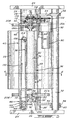
- a coating apparatus which is generally designated by reference numeral 20 and which is especially adapted for coating the surface of a metallic cylinder 22 with an olefinic substance in admixture with a metal oxide, in a manner such as to form on the surface of the cylinder micro-droplets of olefinic substance containing the metal oxide and having substantially uniform size and distribution.
- the cylinder 22 extends vertically and is mounted between a pair of horizontal plates 24,24' for rotation about a central longitudinal axis coincident with the rotation axis of shaft 26 having opposite end portions disposed within cylindrical sleeves 28 and 28' fixed to the plates 24 and 24', respectively.
- the shaft 26 is adapted to be driven by a motor (not shown).
- the coating apparatus 20 includes a vertically extending distribution roll 30, an applicator roll 32 extending parallel to the distribution roll 30 and in pressure contact engagement therewith to form a nip 34, and a transfer roll 36 extending parallel to the roll 30 and in contact engagement therewith to form a nip 38.
- the rolls 30, 32 and 36 are mounted in a housing 40 having a top wall 42, a bottom wall 44, a pair of sidewalls 46,48 and a rear wall 50.
- the housing 40 is pivotally mounted to a column 52 fixed at the ends thereof to plates 24,24' by a pair of arms 54,54' each having one end pivotally connected to the column 52 with a bushing 56.
- the arms 54 and 54' are respectively fixed at their other end to attachment plates 58 and 58' which are integral with the sidewall 48 of the housing 40.
- a support collar 60 is secured to the column 52 for supporting the lower arm 54' and thus the housing 40.
- Such an arrangement enables one to pivotally displace the housing 40 horizontally relative to the cylinder 22.
- the apparatus 20 further includes two strike and catch mechanisms 62a,62b for holding the transfer roll 36 in pressure contact engagement with the cylinder 22 to form a nip 64, as well as a feed system 66 for supplying to the applicator roll 32 the olefinic substance in the form of a dispersion containing the metal oxide as dispersed phase.
- the distribution roll 30 has a solid core 68 of metal provided with a peripheral coating 70 of oxide ceramic material.
- a pair of stub shafts 72,72' integral with the core 68 extends outwardly from the extremities of the roll 30.
- the applicator roll 32 has also a solid core 74 of metal, but is provided with a peripheral covering 76 of polyurethane.
- a pair of stub shafts 78,78' integral with the core 74 extends outwardly from the extremities of the roll 32.
- the transfer roll 36 has a tubular core 80 provided with a peripheral covering 82 of polyurethane which extends part of the length of the core 80.
- the roll 36 is mounted on a central longitudinally extending shaft 84.
- the stub shafts 72,72' and 78,78' and the shaft 84 extend through shaft openings formed in the top and bottom walls 42,44, and are mounted in bearings 86 and 88 within the shaft openings.
- the distribution roll 30 and applicator roll 32 are rotated in register by means of a motor 90 and gearbox 92 which are mounted on the rear wall 48 by a bracket 94, a reinforcing plate 96 being interposed between the bracket 94 and wall 48.
- a sprocket 98 keyed on the drive shaft 100 is connected by a driving chain 102 to a sprocket 104 keyed on the stub shaft 78 of roll 32.
- On the top of the stub shaft 78 there is a keyed gear 106 meshing with gear 108 fixed to the stub shaft 72 of roll 30.
- the pressure exerted at the nip 34 is adjusted by means of two separate pressure adjustment units 110a,110b.
- the unit 110a comprises a cylindrical member 112 rotatably mounted in the shaft opening receiving the stub shaft 78, with the bearings 86 being mounted within the member 112 such that the stub shaft 78 is off-set relative to the central rotation axis of member 112.
- a threaded member 114 provided at one end with a swivelling head 116 and at the other end with a knob 118 is threadably engaged with a mounting element 120 fixed to the top wall 42.
- the head 116 is secured to an arm 122 which is fixedly connected to the member 112.
- a coil spring 124 extends around the threaded member 114 between the knob 118 and the mounting element 120 to prevent loosening of the member 114.
- the pressure adjustment unit 110b is identical to unit 110a and is mounted to the bottom wall 44.
- the knob 118 by rotating the knob 118, one can adjustably move the threaded member 114 so as to displace the arm 122 and partially rotate the cylindrical member 112, thereby adjustably moving the stub shafts 78,78' in a direction towards or away from the stub shafts 72,72' and correspondingly varying the pressure exerted at the nip 34.
- Two further pressure adjustment unit 110c,110d identical to the units 110a,110b are provided for adjustably moving the stub shafts 72,72' in a direction towards or away from the shaft 84 to correspondingly vary the pressure exerted at the nip 38.
- discs 126a and 126b are keyed on stub shafts 78 and 78', respectively; discs 126c and 126d are similarly keyed on stub shafts 72 and 72', respectively.
- the discs 126a and 126c are co-planar and spaced from one another to define a gap 128; the discs 126b and 126d are also co-planar and spaced from one another to define a gap 128'.
- the gaps 128 and 128' are representative of the distance between stub shafts 72 and 78 and of the distance between stub shafts 72' and 78', and are therefore representative of the pressure exerted at the nip 34.
- a similar arrangement is provided for determining the pressure exerted at the nip 38.
- discs 130a and 130b are keyed on the shaft 84 at the ends thereof.
- the discs 126c and 130a are co-planar and spaced from one another to define a gap 132; the discs 126d and 130b are also co-planar and spaced from one another to define a gap 132'.
- the gaps 132 and 132' are representative of the distance between the stub shaft 72 and shaft 84 and of the distance between the stub shaft 72' and shaft 84, and are therefore representative of the pressure exerted at the nip 38.
- the gaps 132,132' one can readily determine the pressure at the nip 38.
- a sealing unit 134 is arranged on the bottom wall 44 for supporting the lower extremities of rolls 30 and 32 while preventing the dispersion from flowing through the shaft openings formed in the wall 44 and receiving stub shafts 72',78'.
- the sealing unit 134 comprises a block 136 having two cylindrical bores formed therein and receiving the stub shafts 72' and 78'.
- a cylindrical seal member 138 having an annular flange 140 is mounted in each bore, each seal member 138 receiving therethrough a respective stub shaft.
- each seal member 138 has an upwardly facing annular sealing surface for sealing engagement with the downwardly facing annular abutment surface defined at the lower extremity of each roll 30,32.
- a coil spring 142 is provided for urging each seal member 138 upwardly against a respective abutment surface to effect the desired sealing engagement while permitting rotation of the rolls 30 and 32.
- the feed system 66 comprises a receptacle 144 mounted to the bottom wall 44 of the housing 40 for containing a bath 146 of olefinic substance in which the metal oxide is dispersed.
- a pulley/agitator member 148 is mounted within the receptacle 144 for rotation in the bath 146 by means of threaded plugs 150 threadably engaged with the walls of the receptacle.
- a belt 152 interconnects the pulley/agitator member 148 with a pulley 154 keyed on a shaft 156 which is driven by a motor 158.
- the belt 152 is formed of an oil-resistant polymeric material such as a butadiene acrylonitrile elastomers.
- the pulley 154 is disposed relative to the applicator roll 32 such that the belt 152 contacts an upper portion thereof.
- a gearbox 160 is provided for varying the speed of rotation of the shaft 156.
- the gearbox 160 is secured to a reinforcing plate 162 mounted to the rear wall 50.
- the pulley/agitator member 148 comprises a central longitudinally extending shaft 164 each end of which is received in a blind-bore 166 formed in each plug 150.
- a pulley 168 is secured to the shaft 164.
- Two pairs of elongated planar blade members 170a,170b and 172a,172b extend laterally outwardly from one side of the pulley 168; the blade members 172a,172b terminate short of the blade members 170a,170b.
- Two pairs of elongated blade members 170'a,170'b and 172'a,172'b also extend laterally outwardly from the other side of pulley 168, the blade members 172'a,172'b terminating short of the blade members 170'a,170'b.
- the blade members 170a,170b extend in a plane which is orthogonal to the plane in which the shorter blade members 172a,172b extend.
- the blade members 170'a,170'b extend in a plane which is orthogonal to the plane in which the shorter members 172'a,172'b extend.
- the blade members 170a,170b on one side of the pulley 168 extend in the same plane as the blade members 172'a,172'b on the other side of the pulley; similarly, the blade members 172a,172b extend in the same plane as the blade members 170'a,170'b.
- Such an arrangement is particularly effective for agitating the bath 146 to form the desired dispersion.
- the dispersion upon passing through the nip 34 forms a film uniformly covering the surface of the ceramic coating 70 of distribution roll 30, the film of olefinic substance containing the metal oxide breaking down into micro-droplets having substantially uniform size and distribution.
- the micro-droplets formed on the roll 30 are carried by the latter to the nip 38 where they are transferred onto the transfer roll 36.
- Two separate strike and catch mechanisms 62a,62b are used for releasably holding the transfer roll 36 in pressure contact engagement with the cylinder 22 to permit the roll 36 to be driven by the cylinder 22 upon rotation thereof and also to enable the micro-droplets to be transferred from the roll 36 onto the cylinder 22 at the nip 64.
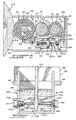
- the strike and catch mechanism 62a which is identical to the mechanism 62b is illustrated in Figs. 9 and 10.
- the mechanism 62a comprises a hook-shaped strike member 174 which is secured to an abutment plate 176 by fasteners 178; the abutment plate 176 has an arcuate abutment edge 180 and is adjustably mounted on the top wall 42 of housing 40 by fasteners 182 extending through slots 184 formed in the plate 176.
- the mechanism 62a further includes a catch member 186 having a pair of opposite parallel fingers 188 with a pin 190 extending therebetween.
- the catch member 186 is pivotally connected by a pivot pin 192 to a lever arm 194 which in turn is pivotally connected to a base plate 196 by pivot pins 198 extending through a pair of spaced-apart opposite lugs 200 integral with the plate 196.
- the base plate 196 is secured by fasteners 202 to a mounting plate 204 fixed by fasteners 206 to a support disc 208 which is fixedly connected to the sleeve 28 and extends in the same plane as the top wall 42.
- the strike and catch mechanism 62b is arranged in a similar manner with the abutment plate 176 thereof being adjustably mounted to the bottom wall 44 and the mounting plate 204 being fixed to a support disc 208' which is fixedly connected to the sleeve 28' and extends in the same plane as the bottom wall 44.
- the strike and catch mechanisms 62a, 62b are operated by engaging the pin 190 of catch member 186 with the hook-shaped strike member 174, as shown in Fig. 10.
- the lever arm 194 is then pivoted about the pivot pins 198 from the position illustrated in broken lines to the position illustrated in solid lines, thereby exerting a pulling action on the catch member 186 to pull the transfer roll 36 against the cylinder 22 and thus releasably hold the roll 36 in pressure contact engagement with the cylinder 22.
- Two separate pressure adjustment systems 210a,210b associated respectively with the strike and catch mechanisms 62a,62b are provided for adjusting the pressure at the nip 64.
- the pressure adjustment system 210a which is identical to the system 210b is illustrated in Figs. 9 and 10. As shown, the system 210a includes a micrometer head 212 which is fixedly mounted on an elongated abutment plate 214 by means of an attachment member 216 fixed to one end of the plate 214 by soldering 218.
- the abutment plate 214 is pivotally connected at the other end thereof to an attachment member 220 by means of a fastener 222 which is rotatably mounted in a through-bore formed in the member 220, thereby enabling the plate 214 to pivotally move in a direction towards of away from the shaft 26 of the cylinder 22.
- the attachment member 220 is fixed to the mounting member 202 by soldering 224.
- the abutment plate 214 has an arcuate edge portion 226 adapted to abut against the arcuate edge 180 of abutment plate 176.
- the micrometer head 212 comprises a thimble 228 which is rotatably mounted on a sleeve 230 for axially moving a spindle 232 outwardly or inwardly of the sleeve 230.
- the spindle 230 is adapted to abut against an abutment member 234 fixed to the mounting plate 204 by soldering 236.
- the thimble 228 By rotating the thimble 228 to adjustably move the spindle in abutting contact engagement with the member 216, one can adjustably pivot the abutment plate 214 in abutting contact engagement with the abutment plate 176 in a direction towards of away from the shaft 26 to correspondingly vary the distance between the shaft 84 of transfer roll 36 and the shaft 26 of cylinder 22 and thereby vary the pressure exerted at the nip 64.
- the micrometer 212 is provided with a spindle lock 238 to lock the spindle at a predetermined length and thereby retain the abutment plate 214 in a selected position relative to the shaft 26.
- the number of micro-droplets transferred onto the transfer roll 36 and ultimately on the cylinder 22 can be carried by varying the speed of rotation of the distribution roll 30 and applicator roll 32.
- the thickness of the micro-droplets can be varied by varying the pressure exerted at the nip 34.
Landscapes
- Life Sciences & Earth Sciences (AREA)
- Engineering & Computer Science (AREA)
- Wood Science & Technology (AREA)
- Coating Apparatus (AREA)
- Application Of Or Painting With Fluid Materials (AREA)
Claims (16)
- Verfahren zum Beschichten eines metallischen Substrates (22) mit einer ölartigen Substanz, umfassend die Verfahrensschritte:a) Bereitstellen eines Trageelementes (30);b) Auftragen der ölartigen Substanz auf die Oberfläche des Trageelementes, um auf dessen Oberfläche einen Film der ölartigen Substanz gleichförmig zu bilden; undc) Übertragen der ölartigen Substanz von dem Trageelement auf eine Oberfläche des metallischen Substrates, wodurch die Oberfläche des metallischen Substrates (22) mit der ölartigen Substanz beschichtet wird, dadurch gekennzeichnet, daß:das Trageelement eine keramische Beschichtung (70) mit einem oxidkeramischen Werkstoff umfaßt;in Verfahrensschritt b) der Film der ölartigen Substanz in Mikro-Tröpfchen aufbricht, die im wesentlichen eine gleichmäßige Größe und Verteilung haben; undin Verfahrensschritt c) die ölartige Substanz in Form von Mikro-Tröpfchen übertragen wird, ohne wesentlich die Größe und Verteilung der Mikro-Tröpfchen zu ändern.
- Verfahren nach Anspruch 1, dadurch gekennzeichnet, daß der oxidkeramische Werkstoff eine verschmolzene Mischung aus Aluminiumoxid und Titanoxid umfaßt.
- Verfahren nach Anspruch 1, dadurch gekennzeichnet, daß das Trageelement (30) eine Verteilwalze (30) ist, mit einer peripheren Beschichtung (70) aus dem oxidkeramischen Werkstoff, die die keramische Beschichtung (70) bildet, und wobei Verfahrensschritt (b) ausgeführt wird durch die Bereitstellung einer Auftragwalze (32), parallel zu der Verteilwalze (30) und in druckkontaktartigem Zusammenwirken mit derselben, um einen ersten Quetschbereich (34) zu bilden, wobei die Auftragwalze (32) und die Verteilwalze (30) deckungsgleich gedreht werden, während die ölartige Substanz dem Quetschbereich (34) zugeführt wird, wobei die ölartige Substanz beim Durchgang durch den ersten Quetschbereich (34) den Film bildet, der die Oberfläche der keramischen Beschichtung (70) gleichförmig bedeckt.
- Verfahren nach Anspruch 1 oder 3, dadurch gekennzeichnet, daß das Substrat (22) ein drehbarer metallischer Zylinder (22) ist und der Verfahrensschritt (c) ausgeführt wird durch Bereitstellung einer Übertragungswalze (36) parallel zu der Verteilwalze (30) und in kontaktartigem Zusammenwirken mit derselben, um einen zweiten Quetschbereich (38) zu bilden, wobei sich die Übertragungswalze (36) parallel zu dem Zylinder (22) erstreckt, die Übertragungsrolle (36) in druckkontaktartigem Zusammenwirken mit dem Zylinder (22) positioniert wird, um einen dritten Quetschbereich (64) zu bilden, und die Übertragungswalze (36) und der Zylinder (22) deckungsgleich gedreht werden, um die Mikro-Tröpfchen an dem Quetschbereich (38) von der Verteilwalze (30) auf die Übertragungswalze (36) zu übertragen und danach die Mikro-Tröpfchen an dem dritten Quetschbereich (64) von der Übertragungsrolle (36) auf den Zylinder (22) zu übertragen.
- Verfahren nach Anspruch 1, 3 oder 4, dadurch gekennzeichnet, daß der Zylinder (22) aus einem elektrolytisch inerten Metall gebildet ist und die Oberfläche des Zylinders (22), auf den die Mikro-Tröpfchen der ölartigen Substanz übertragen werden, eine passivierte Oberfläche ist, und wobei die ölartige Substanz eine olefinische Substanz in Beimischung mit einem Metalloxid umfaßt.
- Vorrichtung zum Beschichten eines metallischen Substrates (22) mit einer ölartigen Substanz, umfassend:dadurch gekennzeichnet, daß das Trageelement eine keramische Beschichtung (70) mit einem oxidkeramischen Werkstoff umfaßt.ein Trageelement (30);Auftragemittel (32) zum Auftragen der ölartigen Substanz auf das Trageelement; undÜbertragungsmittel (36) zum Übertragen der ölartigen Substanz von dem Trageelement auf eine Oberfläche des metallischen Substrates (22), wodurch die Oberfläche des metallischen Substrates mit der ölartigen Substanz beschichtet wird;
- Vorrichtung nach Anspruch 6, dadurch gekennzeichnet, daß der oxidkeramische Werkstoff eine verschmolzene Mischung aus Aluminiumoxid und Titanoxid umfaßt.
- Vorrichtung nach Anspruch 6, dadurch gekennzeichnet, daß das Trageelement (30) eine Verteilwalze (30) mit einer peripheren Beschichtung (70) aus dem oxidkeramischen Werkstoff ist, der die keramische Beschichtung (70) bildet, und wobei die Auftragemittel (32) eine Auftragwalze (32) umfassen, die sich parallel zu der Verteilwalze (30) erstreckt und in druckkontaktartigem Zusammenwirken mit derselben steht, um einen ersten Quetschbereich (34) zu bilden, Mittel (90, 92, 98, 100, 102, 104, 106, 108) zur deckungsgleichen Drehung der Auftragwalze (32) und der Verteilwalze (30), und Zuführungsmittel (66), um die ölartige Substanz dem ersten Quetschbereich (34) zuzuführen, wobei die ölartige Substanz beim Passieren durch den ersten Quetschbereich (34) einen Film bildet, der die Oberfläche der keramischen Beschichtung (70) gleichförmig bedeckt.
- Vorrichtung nach Anspruch 8, dadurch gekennzeichnet, daß die Auftragwalze (32) mit einer peripheren Ummantelung (76) aus einem elastischen, ölresistenten Material versehen ist.
- Vorrichtung nach Anspruch 8, dadurch gekennzeichnet, daß die Auftragwalze (32) und die Verteilwalze (30) jeweils erste und zweite zentrale, in Längsrichtung verlaufende Wellen (78, 72) haben, wobei die Mittel (90, 92, 98, 100, 102, 104, 106, 108) zur deckungsgleichen Drehung der Auftragwalze (32) und der Verteilwalze (30) Antriebsvorrichtungen (90, 92, 98, 100, 102, 104) umfassen, die mit der ersten Welle (78) verbunden sind, um diese anzutreiben, und Kupplungsmittel (106, 108), die die erste Welle (78) mit der zweiten Welle (72) verbinden, um eine Bewegung auf diese zu übertragen.
- Vorrichtung nach Anspruch 10, dadurch gekennzeichnet, daß die Antriebsmittel (90, 92, 98, 100, 102, 104) einen Motor mit variabler Drehzahl (90, 92) umfassen, um die Drehgeschwindigkeit der Auftragwalze (32) und der Verteilwalze (30) zu variieren, um dadurch die Anzahl der auf die Übertragungswalze (36) übertragenen Mikro-Tröpfchen zu variieren.
- Vorrichtung nach Anspruch 8, gekennzeichnet durch ein erstes Druckregelungsmittel (110a, 110b), um den Druck, der an dem ersten Quetschbereich (34) ausgeübt wird, einstellbar zu verändern.
- Vorrichtung nach Anspruch 6 oder 8, dadurch gekennzeichnet, daß das Substrat (22) ein drehbarer metallischer Zylinder (22) ist, wobei die Übertragungsmittel (36) eine Übertragungswalze (36) umfassen, die sich parallel zu der Verteilwalze (30) erstreckt und damit kontaktartig zusammenwirkt, um einen zweiten Quetschbereich (38) zu bilden, wobei sich die Übertragungswalze (36) parallel zu dem Zylinder (22) erstreckt, mit Mitteln (62a, 62b), um die Übertragungswalze (36) in druckkontaktartigem Zusammenwirken mit dem Zylinder (22) zu positionieren, um einen dritten Quetschbereich (64) zu bilden und es der Übertragungswalze (36) zu ermöglichen, durch den Zylinder (22) bei dessen Drehung angetrieben zu werden, wobei die Mikro-Tröpfchen von der Verteilwalze (30) auf die Übertragungswalze (36) an dem zweiten Quetschbereich (38) übertragen werden und danach von der Übertragungswalze (36) auf den Zylinder (22) an dem dritten Quetschbereich (64) übertragen werden.
- Vorrichtung nach Anspruch 13, dadurch gekennzeichnet, daß die Übertragungswalze (36) mit einer peripheren Ummantelung (82) aus einem elastischem, ölresistenten Material versehen ist.
- Vorrichtung nach Anspruch 13, gekennzeichnet durch ein zweites Druckregelungsmittel (110c, 110d), um den Druck, der am zweiten Quetschbereich (38) ausgeübt wird, einstellbar zu verändern.
- Vorrichtung nach Anspruch 13, gekennzeichnet durch ein drittes Druckregelungsmittel (210a, 210b), um den Druck am dritten Quetschbereich (74) einstellbar zu verändern.
Applications Claiming Priority (1)
| Application Number | Priority Date | Filing Date | Title |
|---|---|---|---|
| PCT/JP1995/000863 WO1996034698A1 (en) | 1994-01-14 | 1995-05-02 | Method and apparatus for coating a metallic substrate with an oily substance |
Publications (2)
| Publication Number | Publication Date |
|---|---|
| EP0783377A1 EP0783377A1 (de) | 1997-07-16 |
| EP0783377B1 true EP0783377B1 (de) | 2001-08-01 |
Family
ID=14125894
Family Applications (1)
| Application Number | Title | Priority Date | Filing Date |
|---|---|---|---|
| EP95917501A Expired - Lifetime EP0783377B1 (de) | 1995-05-02 | 1995-05-02 | Verfahren und vorrichtung zum beschichten von metallischen substraten mit ölartigen substanzen |
Country Status (5)
| Country | Link |
|---|---|
| EP (1) | EP0783377B1 (de) |
| JP (1) | JP3526578B2 (de) |
| KR (1) | KR970703819A (de) |
| AU (1) | AU697368B2 (de) |
| DE (1) | DE69522005T2 (de) |
Families Citing this family (2)
| Publication number | Priority date | Publication date | Assignee | Title |
|---|---|---|---|---|
| CN102189747A (zh) * | 2011-04-18 | 2011-09-21 | 张勤英 | 陶瓷印刷机 |
| CN109822356B (zh) * | 2019-04-10 | 2024-01-30 | 福州大学 | 一种涂胶-钻孔-电磁铆接复合装置及其使用方法 |
Family Cites Families (1)
| Publication number | Priority date | Publication date | Assignee | Title |
|---|---|---|---|---|
| CA1334017C (en) * | 1989-04-12 | 1995-01-17 | Adrien Castegnier | High-speed electrocoagulation printing method and apparatus |
-
1995
- 1995-05-02 EP EP95917501A patent/EP0783377B1/de not_active Expired - Lifetime
- 1995-05-02 JP JP53316596A patent/JP3526578B2/ja not_active Expired - Fee Related
- 1995-05-02 AU AU23534/95A patent/AU697368B2/en not_active Ceased
- 1995-05-02 DE DE69522005T patent/DE69522005T2/de not_active Expired - Fee Related
-
1996
- 1996-12-31 KR KR1019960707594A patent/KR970703819A/ko not_active Withdrawn
Also Published As
| Publication number | Publication date |
|---|---|
| JP3526578B2 (ja) | 2004-05-17 |
| AU2353495A (en) | 1996-11-21 |
| AU697368B2 (en) | 1998-10-01 |
| JPH10502873A (ja) | 1998-03-17 |
| HK1001384A1 (en) | 1998-06-19 |
| DE69522005D1 (de) | 2001-09-06 |
| EP0783377A1 (de) | 1997-07-16 |
| KR970703819A (ko) | 1997-08-09 |
| DE69522005T2 (de) | 2002-05-29 |
Similar Documents
| Publication | Publication Date | Title |
|---|---|---|
| US5449392A (en) | Apparatus for coating a metallic substrate with an oily substance | |
| US5538601A (en) | Electrocoagulation printing and apparatus | |
| CA2167955C (en) | Method and apparatus for handling printed sheet material | |
| JPS61181646A (ja) | 平版印刷用インキ計量ロ−ラ− | |
| EP0783377B1 (de) | Verfahren und vorrichtung zum beschichten von metallischen substraten mit ölartigen substanzen | |
| CA2113535C (en) | Method and apparatus for coating a metallic substrate with an oily substance | |
| EP0935174B1 (de) | Elektrophotographische vorrichtung mit nassentwicklung | |
| NZ284867A (en) | Method and apparatus for transferring an oily substance to a metallic substrate using a ceramic-coated applicator | |
| US5908541A (en) | Multicolor electrocoagulation printing method and apparatus | |
| US5693206A (en) | Electrocoagulation printing apparatus | |
| CN1066981C (zh) | 向金属基底上涂敷油类物质的方法和设备 | |
| US4621574A (en) | Dual form planetary inker | |
| JPH082643B2 (ja) | 印刷機のインキングローラーおよび印刷機のインキングローラーの製造方法 | |
| EP0899094B1 (de) | Mehrfarben -Elektrokoagulationsdruckverfahren und Vorrichtung | |
| EP0322816A2 (de) | Druckverfahren | |
| JP2841175B2 (ja) | インキ供給装置 | |
| CA2214606C (en) | Method of preventing anode abrasion during electrocoagulation printing | |
| US5690803A (en) | Method of enhancing transfer of coagulated colloid onto a substrate during electrocoagulation printing | |
| EP0845355B1 (de) | Vorrichtung zum drucken mittels elektrokoagulation | |
| JP3788388B2 (ja) | ペースト塗布装置 | |
| AU703802B2 (en) | Multicolor dynamic printing method and apparatus | |
| US5863402A (en) | Method of preventing anode abrasion during electrocoagulation printing | |
| EP0374482B1 (de) | Vorrichtung zum Vermeiden von unerwünschtem Flüssigkeitsdurchgang an einer Stelle zur Durchflusskontrolle | |
| CA2194128C (en) | Method of increasing coagulation efficiency during electrocoagulation printing | |
| GB1600616A (en) | Coating sheet material with liquids |
Legal Events
| Date | Code | Title | Description |
|---|---|---|---|
| PUAI | Public reference made under article 153(3) epc to a published international application that has entered the european phase |
Free format text: ORIGINAL CODE: 0009012 |
|
| 17P | Request for examination filed |
Effective date: 19970131 |
|
| AK | Designated contracting states |
Kind code of ref document: A1 Designated state(s): DE FR GB IT |
|
| RAP1 | Party data changed (applicant data changed or rights of an application transferred) |
Owner name: TOYO INK MANUFACTURING CO., LTD. |
|
| 17Q | First examination report despatched |
Effective date: 19990413 |
|
| GRAG | Despatch of communication of intention to grant |
Free format text: ORIGINAL CODE: EPIDOS AGRA |
|
| GRAG | Despatch of communication of intention to grant |
Free format text: ORIGINAL CODE: EPIDOS AGRA |
|
| GRAH | Despatch of communication of intention to grant a patent |
Free format text: ORIGINAL CODE: EPIDOS IGRA |
|
| GRAH | Despatch of communication of intention to grant a patent |
Free format text: ORIGINAL CODE: EPIDOS IGRA |
|
| GRAH | Despatch of communication of intention to grant a patent |
Free format text: ORIGINAL CODE: EPIDOS IGRA |
|
| GRAA | (expected) grant |
Free format text: ORIGINAL CODE: 0009210 |
|
| RIN1 | Information on inventor provided before grant (corrected) |
Inventor name: GADBOIS, GILLES Inventor name: CASTEGNIER, ADRIEN |
|
| AK | Designated contracting states |
Kind code of ref document: B1 Designated state(s): DE FR GB IT |
|
| REF | Corresponds to: |
Ref document number: 69522005 Country of ref document: DE Date of ref document: 20010906 |
|
| EN | Fr: translation not filed | ||
| REG | Reference to a national code |
Ref country code: GB Ref legal event code: IF02 |
|
| EN | Fr: translation not filed |
Free format text: BO 01/52 PAGES: 283, IL Y A LIEU DE SUPPRIMER: LA MENTION DE LA NON REMISE. LA REMISE EST PUBLIEE DANS LE PRESENT BOPI. |
|
| ET | Fr: translation filed | ||
| PLBE | No opposition filed within time limit |
Free format text: ORIGINAL CODE: 0009261 |
|
| STAA | Information on the status of an ep patent application or granted ep patent |
Free format text: STATUS: NO OPPOSITION FILED WITHIN TIME LIMIT |
|
| 26N | No opposition filed | ||
| PGFP | Annual fee paid to national office [announced via postgrant information from national office to epo] |
Ref country code: GB Payment date: 20040428 Year of fee payment: 10 |
|
| PGFP | Annual fee paid to national office [announced via postgrant information from national office to epo] |
Ref country code: FR Payment date: 20040510 Year of fee payment: 10 |
|
| PGFP | Annual fee paid to national office [announced via postgrant information from national office to epo] |
Ref country code: DE Payment date: 20040513 Year of fee payment: 10 |
|
| PG25 | Lapsed in a contracting state [announced via postgrant information from national office to epo] |
Ref country code: IT Free format text: LAPSE BECAUSE OF NON-PAYMENT OF DUE FEES Effective date: 20050502 Ref country code: GB Free format text: LAPSE BECAUSE OF NON-PAYMENT OF DUE FEES Effective date: 20050502 |
|
| PG25 | Lapsed in a contracting state [announced via postgrant information from national office to epo] |
Ref country code: DE Free format text: LAPSE BECAUSE OF NON-PAYMENT OF DUE FEES Effective date: 20051201 |
|
| GBPC | Gb: european patent ceased through non-payment of renewal fee |
Effective date: 20050502 |
|
| PG25 | Lapsed in a contracting state [announced via postgrant information from national office to epo] |
Ref country code: FR Free format text: LAPSE BECAUSE OF NON-PAYMENT OF DUE FEES Effective date: 20060131 |
|
| REG | Reference to a national code |
Ref country code: FR Ref legal event code: ST Effective date: 20060131 |